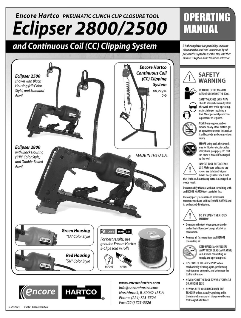
Encore Hartco RAC-1003 User manual

SAFETY INFORMATION
READ THE ENTIRE
MANUAL BEFORE
OPERATING THE TOOL.
SAFETY GLASSES
should always be
worn while operating,
maintaining, or
repairing a tool, or in the vicinity of
a tool in operation.
KEEP HANDS AND
FINGERS AWAY from the
front of jaws area and
all moving parts when operating
or connecting air supply to tool.
Never actuate tool when loading.
Serious injury may result.
DISCONNECT THE AIR SUPPLY
when mechanically clearing a jam,
performing maintenance or repairs,
and whenever the tool is not in use.
MAINTAIN AIR PRESSURE at
85–120 PSI (6–8 BARS) using 1/4”
(6.35mm) ID air hose. Higher
pressure may damage tool.
INJURY PREVENTION—Operate
tool in an unobstructed work area.
Keep others at a safe distance.
Never point the tool toward
yourself or anyone else.
Never use oxygen,
carbon dioxide or any
other bottled gas as a
power source for this
tool—the tool will explode and
cause serious injury.
ENCORE HARTCO
PNEUMATIC
C-RING CLOSURE
TOOLS
BLACK components
RAC-1003 (Standard)
For 1/2” C-Rings
RAC-1001 (Standard)
For 3/4” C-Rings, in 16 or 15 gauge
RAC-1002 (Tight Closure)
For 3/4” C-Rings, in 16 or 15 gauge
RAC-1004 (with
Extended Nose)
For 3/4” C-Rings, in 16 or 15 gauge
C-Ring Tools
1/2” RAC-1003 and 3/4” RAC-1001, RAC-1002, RAC-1004
OPERATING
MANUAL
2019-03-19
www.encorehartco.com
Northbrook, IL 60062 U.S.A.
Phone: (224) 723-5524
Fax: (224) 723-5526
3/4” C-Ring Tool
with Tight Closure
RAC-1002
1/2” C-Ring Closure
Tool RAC-1003
3/4” C-Ring
Closure Tool
with Extended Nose
RAC-1004
3/4” C-Ring
Closure Tool
RAC-1001
Use with Encore Hartco C-Rings
3/4” 15 ga: RC1001, RC1003, RC1004
3/4” 16 ga: RC1005, RC1006,
RC1009
1/2” 16 ga: RC1007,
RC1008

www.encorehartco.com
2
C-Ring Tool Models RAC-1001, RAC-1002, RAC-1003, RAC-1004
78A
40
47
45
78
20
74
55L
206
58
6
5
4
3
1
339
28
51
21
57
56
3
71
86
36
205
50
35L
35R
12 32
31
30
29
89
79
48
49
46 89
43
44
37
18
3
78
27
23
41
16
6
17
208
No. 200 Housing Assembly
23, 27, 28
No. 206 Magazine Assembly 73, 75, 76, 77, 82, 83
No. 205 Pusher Assembly
52, 64, 67, 68, 69, 94, 97
No. 208 Throttle Assembly 9, 10, 11, 12, 13, 14
14 11 12 13 12 11 10 9
No. 201 Piston & Piston Rod Assembly
12, 29, 30, 31, 32, 47, 48, 49, 89
No. 203 Frame Assembly
20, 35R, 35L, 36, 37, 86
No. 202 Blade Assembly 47, 48, 49
910 11 12 13 12 11
83
82 73
76
77
75
64
94
6968
67
52
97
52
210
Parts and assemblies called out in RED have “MODEL SPECIFIC” components.

SPECIFICATIONS
MODEL # RAC-1003 RAC-1001 RAC-1002 RAC-1004
WEIGHT: 3.37 lbs (1.53 kgs) 3.24 lbs (1.47 kgs) 3.24 lbs (1.47 kgs) 3.30 lbs (1.5 kgs)
LENGTH: 10.63” (27 cm) 12.8” (32.5 cm) 12.8” (32.5 cm) 13.78” (35 cm)
WIDTH: 3.74” (9.5 cm) 3.94” (10 cm) 3.94” (10 cm) 3.94” (10 cm)
HEIGHT: 7.87” (20 cm) 7.87” (20 cm) 7.87” (20 cm) 7.87” (20 cm)
AIR SUPPLY: 85-120 PSI 90-110 PSI 90-110 PSI 90-110 PSI
(dry, lubricated air) (5-8 BARS) (6-7 BARS) (6-7 BARS) (6-7 BARS)
MATERIALS: Composite plastic and steel
FEEDING METHOD: Constant force spring
C-RINGS TO USE: 1/2” wide 3/4” wide 3/4” wide 3/4” wide
15ga, galvanized, sharp pt. RC1001 RC1001 RC1001
16ga, galvanized, sharp pt. RC1006 RC1006 RC1006
16 ga, 304 stainless, sharp pt. RC1007
16 ga, 304 stainless, blunt pt. RC1008
Visit www.encorehartco.com for more detailed descriptions of these products. 2019-03-19
UNIVERSAL PARTS
3
Dwg
# Part # Description Qty
1 EHC01001 Set Screw 1
3 EHC01003 Lock Washer 7
4 EHC01004 Air Deector 1
5 EHC01005 Rear Valve Seat 1
6 EHC01006 O-Ring 2
7 EHC01007 Throttle Spring 1
8 EHC01008 Throttle Spring Locator 1
9 EHC01009 Throttle Valve Screw 2
10 EHC01010 Valve Screw Washer 2
11 EHC01011 O-Ring Support 4
12 EHC01012 O-Ring 5
13 EHC01013 O-Ring Center Support 2
14 EHC01014 Throttle Valve Spacer 1
16 EHC01016 Front Valve Seat 1
17 EHC01017 Throttle Stem 1
18 EHC01018 Button Head Cap Screw 1
20 EHC01020 Trigger Guard 1
21 EHC01021 Nyloc Nut 2
23 EHC01023 Stud 2
27 EHC01027 Housing 1
28 EHC01028 Set Screw 2
29 EHC01029 O-Ring 1
30 EHC01030 Piston 1
31 EHC01031 Cylinder Gasket 1
35R EHC0135R Side Plate (Right) 1
35L EHC0135L Side Plate (Left) 1
36 EHC01036 Roll Pin 3
37 EHC01037 Trigger 1
39 EHC01039 Socket Head Cap Screw 4
41 EHC01041 Jaw Bushing 2
43 EHC01043 Latch Pin Clip 1
49 EHC01049 Roller Pin 2
51 EHC01M051 Feeder Arm 1
52 EHC01M052 Washer 2
55L EHC01M55L Feeder Guide Rail 1
56 EHC01056 Washer 2
57 EHC01057 Nut 2
58 EHC01M058 Screw 2
64 EHC01M064 Socket Head Cap Screw 1
67 EHC01M067 Magazine Set 1
69 EHC01M069 Stop Ring 2
71 EHC01071 Feeder Arm Screw 1
74 EHC01074 Jaw Bolt 2
78 EHC01078 Magazine Shim (thick) 1
78A EHC01078A Magazine Shim 1
79 EHC01079 Washer 2
82 EHC02082 Anti-Backup Clip 1
83 EHC01M083 Screw 1
86 EHC01086 Screw 1
89 EHC01089 Nyloc Nut 3
94 EHC01M094 Pin 2
97 EHC1M097 Spring Roller 1
MODEL-SPECIFIC PARTS
Dwg 1/2” 3/4” 3/4”Tight 3/4” Extend
# Standard Standard Closure Nose Description Qty
RAC-1003 RAC-1001 RAC-1002 RAC-1004
32 EHC01032 EHC01032 EHC02032 EHC02032 Piston Stop Spacer 1
40 EHC01040 EHC04040 EHC02040 EHC05040 Upper Jaw 1
44 EHC01044 EHC01044 EHC01044 EHC05044 Latch Spring 1
45 EHC01045 EHC03045 EHC01045 EHC05045 Latch 1
46 EHC01046 EHC01046 EHC02046 EHC01046 Roller 4
47 EHC01047 EHC03047 EHC02047 EHC05047 Feeder Blade 1
48 EHC01048 EHC03048 EHC02048 EHC03048 Piston Rod 1
50 EHC01050 EHC04050 EHC02050 EHC05050 Lower Jaw 1
68 EHC01M068 EHC02M068 EHC02M068 EHC02M068 Pusher 1
73 EHC11M073 EHC02M073 EHC02M073 EHC02M073 Magazine Body 1
75 EHC01075 EHC02075 EHC02075 EHC02075 Magazine Spring 1
76 EHC01M076 EHC02M076 EHC02M076 EHC02M076 Magazine Shoe 1
77 EHC01077 EHC02077 EHC02077 EHC02077 Roll Pin 1
Dwg 1/2” 3/4” 3/4”Tight 3/4” Extend
# Standard Standard Closure Nose Description Qty
RAC-1003 RAC-1001 RAC-1002 RAC-1004
200 EHC01200 EHC01200 EHC01200 EHC01200 Housing Assembly 1
201 EHC01201 EHC03201 EHC02201 EHC05201 Piston & Rod Assembly 1
202 EHC01202 EHC03202 EHC02202 EHC05202 Piston Rod Assembly 1
203 EHC01203 EHC01203 EHC01203 EHC01203 Frame Assembly 1
205 EHC01M205 EHC02M205 EHC02M205 EHC02M205 Pusher Assembly 1
206 EHC11M206 EHC02M206 EHC02M206 EHC02M206 Magazine Assembly 1
208 EHC01208 EHC01208 EHC01208 EHC01208 Throttle Assembly 1
210 EHC01M210 EHC01M210 EHC01M210 EHC01M210 Spring Assembly 1
ASSEMBLIES
C-Ring Tool Models:
RAC-1003 (1/2”), and RAC-1001 (3/4”),
RAC-1002 (3/4”) and RAC-1004 (3/4”)

TO GET STARTED
Install a ¼” NPT tting (not included) into air inlet opening in the bottom of
the housing assembly (#27 on page 2), using suitable thread sealant.
AIR FILTER AND REGULATOR
The air line should have an attached air line lter and regulator sucient to
provide a constant and even ow of clean, dry air. The lter should be install-
ed as close as possible to the tool. Dirt or moisture in the air line will adversely
aect the smooth operation of the tool and decrease its serviceable life.
AIR PRESSURE
Air pressure should be maintained at 85-120 PSI (6-8 bars) using 1/4”
(6.35mm) ID air hose. Do not operate the tool at air pressures above 120 PSI (8
bars), as this may cause damage to it.
RECOMMENDED DAILY MAINTENANCE
Add 4-5 drops of air tool oil (10-weight recommended) to air inlet hose tting
(A) on the bottom of the handle (Fig 1).
Although the jaws and other moving parts of
the tool do not need to be oiled daily, periodic
oiling in small amounts may increase the
serviceable life of tools that receive heavy use.
LOADING CRINGS
1. With Pusher at nose of tool, slide C-rings
onto end of magazine, ring points facing away from tool. Push C-rings
forward and past the Clip Anti-Backup on the magazine.
2.
Pull the Pusher over the
C-rings, to the end of the
magazine. Allow C-rings to
slide forward.
3. Engage the Pusher with
the last C-ring, and push
the rings to front of tool.
Loading is complete.
OPERATION
Before using tool, review Safety Information on front page of manual.
In most operations, the tool is positioned at 90 degrees to the material being
enclosed (Fig. 2). During assembly, when
“grabbing”wires, the tool is often used as
a pusher/puller. Operator should always
choose the approach that places the least
amount of stress on the tool.
Hold the tool rmly and operate it in the
direction of the application motion without
excessive stretching. The tool should make
a complete closure of the ring. If closure
is incomplete, check that the application
is properly positioned and that the tool is
cycling completely. See “Troubleshooting” for
tips on resolving problems.
www.encorehartco.com • [email protected]om
Northbrook, Illinois 60062 U.S.A.
Phone: (224) 723-5524 • Fax: (224) 723-5526
2019-03-19
4
C-RING TOOL OPERATING INSTRUCTIONS
TROUBLE SHOOTING
ISSUE: AIR LEAK
1. The front leaks while tool is motionless.
A. The Front Valve Seat (Part #16 ) is not locked deep enough.
B. The Inlet Bushing (Part #59) is not closed enough but it would
not aect any operation.
2. The front leaks while tool is in motion.
A. The Rear Valve Seat (Part #5 ) is locked too deep.
B. The Inlet Bushing (Part #59) is not closed enough but it would
not aect any operation.
TO LOCATE AND CORRECT AIR LEAKS
If an Adjustable Valve Seat is turned too far, the opposite Valve will be
raised from its Bushing Seat, causing air leakage. To correct, back o
Adjustable Valve Seat until leak stops. If leaks do not stop, check Piston
(#30) and Piston O-Rings (#29). Reseat or replace, as indicated.
ISSUE: TRIGGER IS STICKING OR NOT WORKING
1. The Front Valve Seat (#16) and the Rear Valve Seat (#5) are locked too
deep, making the Throttle Assembly (#208) immovable.
2. Lack of maintenance causing rust to form on the Throttle Assembly (#208),
making it immovable.
3. The O-Ring (#29) is worn and torn, causing the Piston (#30) to loosen.
4. The Throttle Stem (#17) could not bounce out. It may be stuck to Front
Valve Seat(#16) with consolidation glue (?).
ISSUE: C-RINGS FLY OUT DURING OPERATION
1. The jaws of the tool are too tight. The Jaw Bushing (#41) is worn and torn
and must be replaced.
2. The Jaws of the tool (#40, #50) are not smooth and hit on a C-Ring.
Remove Flexlock Nuts (#21) and Jaw Bolts (#74). Take out Jaws and
replace.
3. The C-Rings are of poor quality, or not the right size for the tool.
ISSUE: TOOL DOESN’T FORM C-RINGS INTO PROPER SHAPE
1. The Jaws (#40, #50) are broken. Remove Flexlock Nuts (#21) and Jaw Bolts
(#74). Take out Jaws and replace.
2. The Piston & Piston Rod Assembly (#201) is broken or worn. Replace.
3. The C-Rings are of poor quality, or not the right size for the tool.
When working with the tool, lways take care to put it down lightly to avoid
damaging the body or the magazine. Do not drop the tool!
Tools not operating properly should be removed from service at once and
checked for worn or damaged parts.
WHEN NOT IN OPERATION
When done using your C-Ring tool, and before performing maintenance or
part replacements, the compressed air must be disconnected.
Your C-Ring tool should be regularly cleaned, especially when pushing
it into foam. Moisture, dirt or other foreign matter inside the tool will
reduce its operational eciency. After every use, check for and clear/clean
o any particles in the jaws (#40, #50). Proper handling, operation and
maintenance of your tool will assure it a long working life.
If tool will not be in operation for a longer period, it should be covered or
stowed to keep dust o. Store tool at a moderate temperature and avoid
humid environments.
Fig. 2
A
Fig. 1
This manual suits for next models
3
Table of contents
Other Encore Hartco Power Tools manuals
Popular Power Tools manuals by other brands
Bosch
Bosch 1944LCD Operating/safety instructions

Avdel
Avdel Genesis G4 HD Heavy Duty instruction manual

FISCHER DAREX
FISCHER DAREX 740310 Instructions for use

TOOLCRAFT
TOOLCRAFT 2521200 operating instructions
Yokota
Yokota TKA80A manual
Studio Designs
Studio Designs PRO CRAFT STATION 13245 Assembly instructions
