Endace DAG 3.6GE User manual

EDM01.05-04r1
DAG 3.6GE Card User Manual
2.5.5r1

Endace Measurement Systems Limited
http://www.endace.com EDM01.05-04r1 DAG 3.6GE User Manual
Copyright, all rights reserved. Revision 7. 22 September 2005.
Leading Network Intelligence
Copyright © 2005.
Published by:
Endace Measurement Systems®Ltd
Building 7
17 Lambie Drive
PO Box 76802
Manukau City 1702
New Zealand
Phone: +64 9 262 7260
Fax: +64 9 262 7261
www.endace.com
International Locations
New Zealand Americas Europe, Middle East & Africa
Endace Technology®Ltd
Level 9
85 Alexandra Street
PO Box 19246
Hamilton 2001
New Zealand
Phone: +64 7 839 0540
Fax: +64 7 839 0543
www.endace.com
Endace USA®Ltd
Suite 220
11495 Sunset Hill Road
Reston
Virginia 20190
United States of America
Phone: ++1 703 382 0155
Fax: ++1 703 382 0155
www.endace.com
Endace Europe®Ltd
Sheraton House
Castle Park
Cambridge CB3 0AX
United Kingdom
Phone: ++44 1223 370 176
Fax: ++44 1223 370 040
www.endace.com
All rights reserved. No part of this publication may be reproduced, stored in a retrieval system, or transmitted, in
any form or by any means electronic, mechanical, photocopying, recording, or otherwise, without the prior
written permission of the publisher. Prepared in Hamilton, New Zealand.

Endace Measurement Systems Limited
http://www.endace.com EDM01.05-04r1 DAG 3.6GE User Manual
Copyright, all rights reserved. Revision 7. 22 September 2005.
Typographical Conventions Used in this Document
•Command-line examples suitable for entering at command prompts are displayed in
mono-space courier font. The font is also used to describe config file data
used as examples within a sentence. An example can be in more than one sentence.
Results generated by example command-lines are also displayed in mono-space
courier font.
•The software version references such as 2.3.x, 2.4.x, 2.5.x are specific to Endace
Measurement Systems and relate to Company software products only.
Protection Against Harmful Interference
When present on product this manual pertains to and indicated by product labelling, the statement "This device complies
with part 15 of the FCC rules" specifies the equipment has been tested and found to comply with the limits for a Class A
digital device, pursuant to Part 15 of the Federal Communications Commission [FCC] Rules.
These limits are designed to provide reasonable protection against harmful interference when the equipment is operated in a
commercial environment.
This equipment generates, uses, and can radiate radio frequency energy and, if not installed and used in accordance with the
instruction manual, may cause harmful interference to radio communications.
Operation of this equipment in a residential area is likely to cause harmful interference in which case the user will be
required to correct the interference at his own expense.
Extra Components and Materials
The product that this manual pertains to may include extra components and materials that are not essential to its basic
operation, but are necessary to ensure compliance to the product standards required by the United States Federal
Communications Commission, and the European EMC Directive. Modification or removal of these components and/or
materials, is liable to cause non compliance to these standards, and in doing so invalidate the user’s right to operate this
equipment in a Class A industrial environment.

Endace Measurement Systems Limited
http://www.endace.com EDM01.05-04r1 DAG 3.6GE User Manual
Copyright, all rights reserved. i Revision 7. 22 September 2005.
Table of Contents
1.0 PREFACE...........................................................................................................................1
1.1 User Manual Purpose......................................................................................................1
1.2 DAG 3.6GE Card Product Description...........................................................................2
1.3 DAG 3.6GE Card Architecture.......................................................................................2
1.4 DAG 3.6GE Card Extended Functions...........................................................................3
1.5 DAG 3.6GE Card System Requirements........................................................................3
2.0 INSTALLING DAG 3.6GE CARD..................................................................................5
2.1 Insert DAG 3.6GE Card into PC.....................................................................................5
2.2 Connect DAG 3.6GE Card Ports ....................................................................................6
2.3 DAG 3.6GE Card Sensitivity..........................................................................................6
3.0 CONFIDENCE TESTING................................................................................................7
3.1 Interpreting DAG 3.6GE Card LED Status.....................................................................7
3.2 DAG 3.6GE Card LED Display Functions.....................................................................8
3.3 Configuration in WYSYCC style....................................................................................9
3.4 DAG 3.6GE Card Capture Session...............................................................................10
3.5 Inspect Interface Statistics.............................................................................................11
3.6 Reporting Problems.......................................................................................................13
4.0 RUNNING DATA CAPTURE SOFTWARE................................................................15
4.1 Starting Capture Session...............................................................................................15
4.2 High Load Performance................................................................................................17
5.0 SYNCHRONIZING CLOCK TIME..............................................................................19
5.1 Configuration Tool Usage.............................................................................................20
5.2 Time Synchronization Configurations..........................................................................21
5.2.1 Single Card no Reference Time Synchronization...................................................21
5.2.2 Two Cards no Reference Time Synchronization....................................................22
5.2.3 Card with Reference Time Synchronization...........................................................23
5.3 Synchronization Connector Pin-outs.............................................................................25
6.0 DATA FORMATS OVERVIEW....................................................................................27
6.1 Data Formats.................................................................................................................27
7.2 Timestamps...................................................................................................................29

Endace Measurement Systems Limited
http://www.endace.com EDM01.05-04r1 DAG 3.6GE User Manual
Copyright, all rights reserved. ii Revision 7. 22 September 2005.
USE THIS SPACE FOR NOTES

Endace Measurement Systems Limited
http://www.endace.com EDM01.05-04r1 DAG 3.6GE User Manual
Copyright, all rights reserved. 1 Revision 7. 22 September 2005.
1.0 PREFACE
Introduction The installation of the Endace DAG 3.6GE card on a PC begins with
installing the operating system and the Endace software. This is followed
by fitting the card and connecting the ports.
Viewing this
document This document, DAG 4.2GE Card User Manual is available on the
installation CD.
In this chapter This chapter covers the following sections of information.
•User Manual Purpose
•DAG 3.6GE Card Product Description
•DAG 3.6GE Card Architecture
•DAG 3.6GE Card Extended Functions
•DAG 3.6GE Card System Requirements
1.1 User Manual Purpose
Description The purpose of this DAG 3.6GE Card User Manual is to identify and
describe:
•Installing DAG 3.6GE Card
•Confidence Testing
•Running Data Capture Software
•Synchronizing Clock Time
•Data Formats Overview
Pre-requisite This document presumes the DAG card is being installed in a PC already
configured with an operating system.
A copy of the Debian Linux 3.1 (Sarge) is available as a bootable ISO
image on one of the CD's shipped with the DAG card.
To install on the Linux/FreeBSD operating system, follow the instructions
in the document EDM04.05-01r1 Linux FreeBSD Installation Manual,
packaged in the CD shipped with the DAG card.
To install on a Windows operating system, follow the instructions in the
document EDM04.05-02r1 Windows Installation Manual, packaged in the
CD shipped with the DAG card.
Endace Measurement Systems Limited
http://www.endace.com EDM01.05-04r1 DAG 3.6GE User Manual
Copyright, all rights reserved. 2 Revision 7. 22 September 2005.
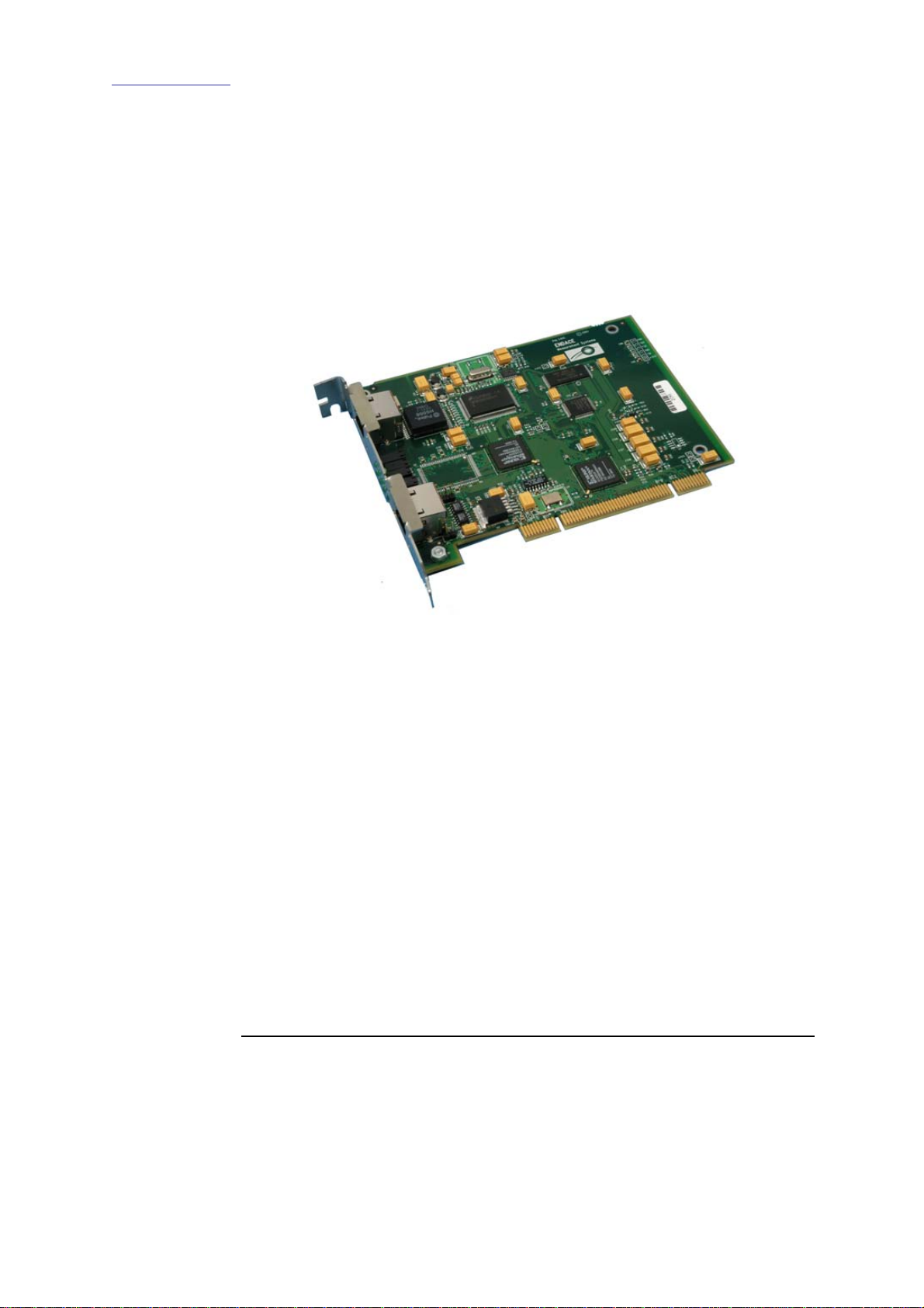
1.2 DAG 3.6GE Card Product Description
The DAG Ethernet port will operate in half duplex or full duplex modes.
The DAG 3.6GE card by default finds the fastest link configuration
possible with the peer device using Ethernet Autonegotiation.
Figure Figure 1-1 shows the DAG 3.6GE series PCI card.
Figure 1-1. DAG 3.6GE series PCI Card.
1.3 DAG 3.6GE Card Architecture
Description The DAG 3.6GE PCI-bus card is designed for cell and packet capture and
generation on IP networks.
Serial Ethernet data is received by the interface, and fed through a framer
into the first of the two Xilinx FPGAs.
This FPGA contains an Ethernet processor and the DUCK timestamp
engine.
Because of component close association, packets or cells are time-stamped
accurately. Time stamped packet records are stored in the second FPGA,
which interfaces to the PCI bus. All packet records are written to host PC
memory during capture operations.
Continued on next page

Endace Measurement Systems Limited
http://www.endace.com EDM01.05-04r1 DAG 3.6GE User Manual
Copyright, all rights reserved. 3 Revision 7. 22 September 2005.
1.3 DAG 3.6GE Card Architecture, continued
Figure Figure 1-2 shows the DAG 3.6GE Card major components and process
flow.
Figure 1-2. DAG 3.6GE Card Major Components and Process Flow.
DAG card as a
NIC card The DAG 3.6GE card has a single 10/100/1000 Mbps Copper Ethernet
port. This is configured as if the DAG was a NIC, and can be connected to
a hub, switch or router port directly.
The DAG 3.6GE can also be connected to a NIC card using an Ethernet
cross-over cable. The DAG captures all packets received on this port,
similar to a NIC in promiscuous mode.
1.4 DAG 3.6GE Card Extended Functions
Description The DAG 3.6GE functionality can be extended in many ways.
enable effective use of extended functions.
1.5 DAG 3.6GE Card System Requirements
Description The DAG 3.6GE and associated data capture system minimum operating
requirements are:
•PC, at least Pentium II 400 MHz, Intel 440BX, GX or newer chip
set
•256 MB RAM
•At least one free PCI free slot with 3.3V and 5V power
•Software distribution free space of 30MB
Continued on next page

Endace Measurement Systems Limited
http://www.endace.com EDM01.05-04r1 DAG 3.6GE User Manual
Copyright, all rights reserved. 4 Revision 7. 22 September 2005.
1.5 DAG 3.6GE Card System Requirements, continued
Operating
system For convenience, the Debian 3.1 [Sarge] Linux system is included on the
Endace Software Install CD. Endace currently supports Windows XP,
Windows Server 2000, Windows Server 2003, FreeBSD, RHEL 3.0, and
Debian Linux operating systems.
Different
system For advice on using a system substantially different from that specified

Endace Measurement Systems Limited
http://www.endace.com EDM01.05-04r1 DAG 3.6GE User Manual
Copyright, all rights reserved. 5 Revision 7. 22 September 2005.
2.0 INSTALLING DAG 3.6GE CARD
Introduction The DAG 3.6GE card can be installed in any free Bus Mastering PCI slot.
Although the driver supports up to four DAG cards by default in one
system, due to bandwidth limitations there should not be more than one
card on a single PCI-bus.
The cards make very heavy use of PCI-bus data transfer resources. This is
not usually a limitation as for most applications a maximum of two cards
only can be used with reasonable application performance.
In this chapter This chapter covers the following sections of information.
•Insert DAG 3.6GE Card into PC
•Connect DAG 3.6GE Card Ports
•DAG 3.6GE Card Sensitivity
2.1 Insert DAG 3.6GE Card into PC
Description Inserting the DAG 3.6GE card into a PC involves accessing the bus slot,
fitting the card, and replacing the bus slot screw.
Procedure Follow these steps to insert the DAG 3.6GE card into a PC.
Step 1. Access bus Slot
Power computer down.
Remove PCI-bus slot cover.
Step 2. Fit Card
Insert into PCI-X bus slot.
Step 3. Replace bus Slot Screw
Secure card with screw.
Step 4. Power up Computer

Endace Measurement Systems Limited
http://www.endace.com EDM01.05-04r1 DAG 3.6GE User Manual
Copyright, all rights reserved. 6 Revision 7. 22 September 2005.
2.2 Connect DAG 3.6GE Card Ports
Description There are two RJ45 connectors on the DAG 3.6GE card.
The upper connector, furthest from PCI connector, is the network
monitoring port. This can be connected directly to an Ethernet Hub,
Switch or Router port with a standard Ethernet cable. The monitoring port
can also be connected directly to a NIC card using an Ethernet cross-over
cable.
The second DAG 3.6GE card RJ45 socket, near PCI connector, is for time
synchronization input. This socket should never be connected to an
Ethernet network or telephone line.
2.3 DAG 3.6GE Card Sensitivity
Description The DAG 3.6GE card monitoring port conforms to IEEE 802.3 standard
for Ethernet.
The standard specifies a maximum cable length of 100 metres for 10Base-
T, 100-BaseTX, and 1000Base-T operation over unshielded twisted pair
(CAT5) cable.
By default DAG 3.6GE card automatically detects line speed of either 10,
100, or 1000Mbps.
Light link status lights indicate the network is detected correctly.
Activity lights indicate network traffic.
Endace Measurement Systems Limited
http://www.endace.com EDM01.05-04r1 DAG 3.6GE User Manual
Copyright, all rights reserved. 7 Revision 7. 22 September 2005.
3.0 CONFIDENCE TESTING
Introduction The confidence testing is a process to determine the DAG 3.6GE card is
functioning correctly.
The process also involves a card capture session, and demonstrates
configuration in the style of 'What You See You Can Change', WYSYCC.
Interface statistics are also inspected during this process.
In this chapter This chapter covers the following sections of information.
•Interpreting DAG 3.6GE Card LED Status
•DAG 3.6GE Card LED Display Functions
•Configuration in WYSYCC style
•DAG 3.6GE Card Capture Session
•Inspect Interface Statistics
•Reporting Problems
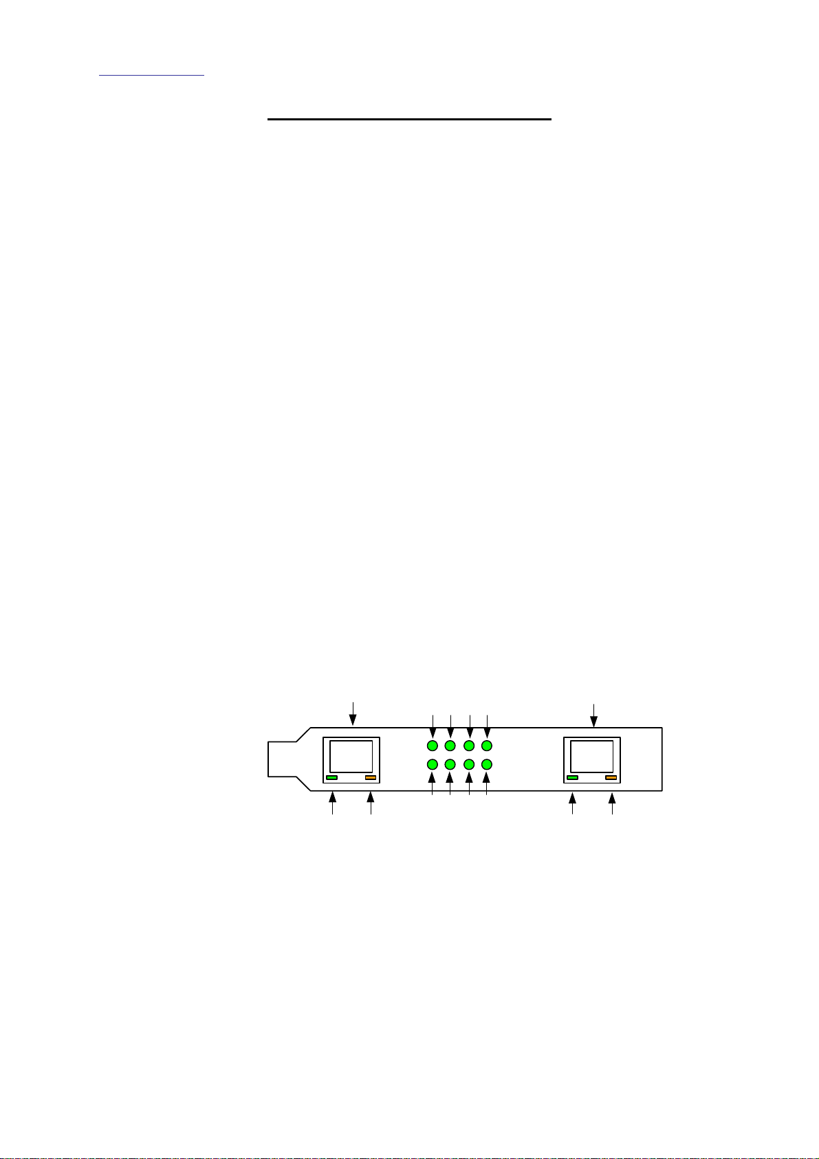
3.1 Interpreting DAG 3.6GE Card LED Status
Description The DAG 3.6GE has 12 status LED’s with ten coloured green and two
coloured orange.
On the DAG 3.6GE card the LED 3 should come on when the card is
powered up.
Figure Figure 3-1 shows the DAG 3.6GE card LED locations.
Ethernet Port
6
12 11
410
5 39
1
2
Synchronization Input
NOT Ethernet
NOT Telephone
8
7
Figure 3-1. DAG 3.6GE Card LED Status LEDs.
Endace Measurement Systems Limited
http://www.endace.com EDM01.05-04r1 DAG 3.6GE User Manual
Copyright, all rights reserved. 8 Revision 7. 22 September 2005.
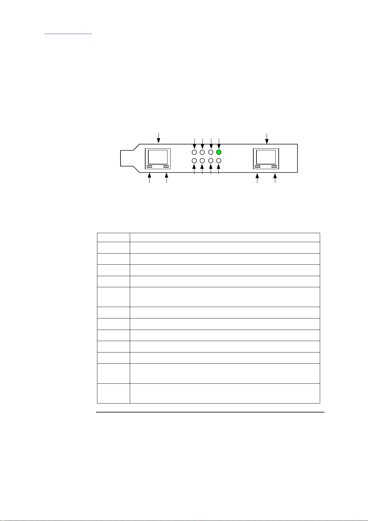
3.2 DAG 3.6GE Card LED Display Functions
Description The function of the DAG 3.6GE card LED displays include indication of
packet capture activity and links on ports A and B, and PPS signals.
Figure Figure 3-2 shows the correct LED state for DAG 3.6GE LED status on
power-up with no network connection.
Ethernet Port
6
12 11
410
539
1
2
Synchronization Input
NOT Ethernet
NOT Telephone
8
7
Figure 3-2. LED State for DAG 3.6GE Card With no network connection.
LED on stages The following table describes the LED display definitions:
LED Description
Receive activity.
LED 1
LED 2 Link up.
LED 3 PCI [Lower] FPGA successfully programmed.
LED 4 PP [Upper] FPGA successfully programmed.
LED 5 Burst manager run; Indicates card is capturing packets and
transferring them to the host.
LED 6 Tap mode; Always OFF on DAG 3.6 GE.
LED 7 10Base-T Link Up
LED 8 100Base-TX Link Up
LED 9 1000Base-T Link Up
LED 10 Reserved.
LED 11 PPS Out: Pulse Per Second Out; Indicates card is sending a
clock synchronization signal.
LED 12 PPS In: Pulse Per Second Out; Indicates card is receiving an
external clock synchronization signal.
Continued on next page

Endace Measurement Systems Limited
http://www.endace.com EDM01.05-04r1 DAG 3.6GE User Manual
Copyright, all rights reserved. 9 Revision 7. 22 September 2005.
3.2 DAG 3.6GE Card LED Display Functions, continued
Configuration
utility The dagthree utility supports configuration status and physical layer
interface statistics for the DAG 3.x series of cards.
In a troubleshooting configuration options –si should be passed to the
tool to watch physical and framing layers operational status.
More details about the meaning of the various bits are supplied through
the help page (dagthree –h) as well as via the manual page.
3.3 Configuration in WYSYCC style
Description Configuration in WYSYCC is the 'What You See You Can Change' style.
Running the command dagthree alone shows the current configuration.
Each of the items displayed can be changed as follows:
Configuration
options reset reset the ethernet framers, set auto mode
default reset the ethernet framer, set auto mode
auto set autonegotiate mode, card will detect rate
10 force 10BaseT mode, 10Mbps
100 force 100BaseTX mode, 100Mbps
1000 force 1000BaseT mode, 1000Mbps
[no]varlen dis/enable variable length capture. Otherwise
record length padded to slen.
slen=X capture X bytes of the packet content
For instance, if the card is configured fixed length capture (novarlen), but
configuration to variable length capture is wanted, removing or adding the
"no" prefix will change the setting. Simply type:
dag@endace:~$ dagthree -d dag0 varlen
link noreset auto enablea
packet varlen slen=48
packetA drop=0
pci 33MHz 32-bit buf=32MB rxstreams=1 txstreams=0
mem=32:0
Once the card has been configured the interface statistics are inspected to
check the card has correctly detected the links.
dag@endace:~$ dagthree -d dag0 -si

Endace Measurement Systems Limited
http://www.endace.com EDM01.05-04r1 DAG 3.6GE User Manual
Copyright, all rights reserved. 10 Revision 7. 22 September 2005.
3.4 DAG 3.6GE Card Capture Session
Description A successful DAG 3.6GE card capture session is accomplished by
checking the card has correctly detected the link. This is followed by
configuring the DAG card for normal use.
Procedure Follow these steps for a successful DAG 3.6GE card capture session.
Step 1. Check Cabling
Ensure cabling is correctly connected and that RJ45 connectors are clipped
into the sockets.
Step 2. Understand link layer configuration
Learn about the link layer configuration in use at the network link being
monitored.
Important parameters include specific scrambling options in use.
If the information cannot be obtained reliably, the card can be made to work
by varying the parameters until data is arriving at the host system.
Step 3. Check FPGA Images are Loaded
Ensure the most recent pair of FPGA images have been loaded onto the
card. The link status and activity LEDs will not activate until the upper
FPGA firmware is downloaded.
dag@endace:~$ dagrom -rvp –d dag0 -f xilinx/dag36epci-
erf.bit
dag@endace:~$ dagld -x –d dag0 –f xilinx/dag36gepp-erf.bit
dag@endace:~$ dagthree -d dag0
link noreset auto enablea
packet novarlen slen=48 noalign64
packetA drop=0
pci 33MHz 32-bit buf=32MB rxstreams=1 txstreams=0 mem=0:0
NOTE: The dagld step has been missed if the card read-out looks like this:
dag@endace:~$ dagthree -d dag0
link noreset 100
packet novarlen slen=1128481603 noalign64
packetA drop=1229539657
pci 33MHz 32-bit buf=32MB rxstreams=1 txstreams=0 mem=0:0
Continued on next page

Endace Measurement Systems Limited
http://www.endace.com EDM01.05-04r1 DAG 3.6GE User Manual
Copyright, all rights reserved. 11 Revision 7. 22 September 2005.
3.4 DAG 3.6GE Card Capture Session, continued
Procedure,continued
Step 4. Configure DAG 3.6GE Card for normal use
The dagthree default command is always used:
dag@endace:~$ dagthree default
link noreset auto enablea
packet novarlen slen=48 noalign64
packetA drop=0
pci 33MHz 32-bit buf=32MB rxstreams=1 txstreams=0 mem=32:0
3.5 Inspect Interface Statistics
Description Once the card has been configured, the interface statistics are inspected to
check the card is locked to the data stream.
dag@endace:~$ dagthree -d dag0 -si
The tool displays a number of status bits that have occurred since last
reading. The following example shows the interval is set to one second via
the -i option.
Spd Link Speed, 10, 100 or 1000 Mbps
Lnk Link state
FD Full Duplex
MA Device is link master
Neg Auto-negotiation completed (Auto mode only)
RF Remote Fault Detected Error
JB Jabber Detected Error
The following example is for a card with no valid input:
dag@endace:~$ dagthree -d dag0 -si
Spd Lnk FD MA Neg RF JB
1000 0 0 0 0 0 0
1000 0 0 0 0 0 0
1000 0 0 0 0 0 0
The following is an example for a card locked to a 10Base-T stream:
dag@endace:~$ dagthree -d dag0 -si
Spd Lnk FD MA Neg RF JB
100 1 1 0 1 0 0
100 1 1 0 1 0 0
100 1 1 0 1 0 0
Continued on next page

Endace Measurement Systems Limited
http://www.endace.com EDM01.05-04r1 DAG 3.6GE User Manual
Copyright, all rights reserved. 12 Revision 7. 22 September 2005.
3.5 Inspect Interface Statistics, continued
Description,continued
The following example is for a card locked to a 100base-TX stream:
dag@endace:~$ dagthree -d dag0 -si
Spd Lnk FD MA Neg RF JB
100 1 1 0 1 0 0
100 1 1 0 1 0 0
100 1 1 0 1 0 0
The following example is for a card locked to a 1000base-T stream:
dag@endace:~$ dagthree -d dag0 -si
Spd Lnk FD MA Neg RF JB
1000 1 1 0 1 0 0
1000 1 1 0 1 0 0
1000 1 1 0 1 0 0
If the RF or JB bits are 1's, this indicates a problem with the network link.
This may or may not be related to the configuration of the DAG 3.6GE
card.
Check all cabling, ensuring that runs are not too long and that plugs are
firmly clipped into their connectors. Check error condition detectors or
counters on the Ethernet equipment.

Endace Measurement Systems Limited
http://www.endace.com EDM01.05-04r1 DAG 3.6GE User Manual
Copyright, all rights reserved. 13 Revision 7. 22 September 2005.
3.6 Reporting Problems
Description If there are unresolved problems with a DAG card or supplied software,
contact Endace Technical Support via the email address
[email protected]. Supplying sufficient information in an email
enables effective response.
Problem
checklist The exact information available to users for trouble, cause and correction
analysis may be limited by nature of the problem. The following items
assist a quick problem resolution:
Ref Item
1. DAG card[s] model and serial number.
2. Host PC type and configuration.
3. Host PC operating system version.
4. DAG software version package in use.
5. Any compiler errors or warnings when building DAG driver or
tools.
6. For Linux and FreeBSD, messages generated when DAG device
driver is loaded. These can be collected from command dmesg,
or from log file /var/log/syslog.
7. Output of daginf -v.
8. Firmware versions from dagrom –x.
9. Physical layer status reported by:
dagthree
10. Network link statistics reported by:
dagthree –si
11. Network link configuration from the router where available.
12. Contents of any scripts in use.
13. Complete output of session where error occurred including any
error messages from DAG tools. The typescript Unix utility
may be useful for recording this information.
14. A small section of captured packet trace illustrating the problem.

Endace Measurement Systems Limited
http://www.endace.com EDM01.05-04r1 DAG 3.6GE User Manual
Copyright, all rights reserved. 14 Revision 7. 22 September 2005.
USE THIS SPACE FOR NOTES

Endace Measurement Systems Limited
http://www.endace.com EDM01.05-04r1 DAG 3.6GE User Manual
Copyright, all rights reserved. 15 Revision 7. 22 September 2005.
4.0 RUNNING DATA CAPTURE SOFTWARE
Introduction For a typical measurement session, ensure the driver is loaded, the
firmware has been downloaded, and the card has been configured.
In this chapter This chapter covers the following sections of information.
•Starting Capture Session
•High Load Performance
4.1 Starting Capture Session
Description The various tools used for data capture are in the tools sub-directory.
For a typical measurement session, ensure the driver is loaded, the
firmware has been downloaded, and the card is configured.
The integrity of the card’s physical layer is then set and checked.
Process Starting a data capture session is described in the following process.
Process Description
Setting capture session
parameters Parameters are set with dagthree.
The card can operate in two modes, variable
length capture (varlen), and fixed length
capture (novarlen).
In variable length capture mode, a maximum
capture size is set with slen=N bytes. This
figure should be in the range 32 to 2044 and is
rounded down to the nearest multiple of 4.
Packets longer than slen are truncated. Packets
shorter than slen will produce shorter records,
saving bandwidth and storage space. Full packet
capture for example:
tools/dagthree –d dag0 varlen
slen=1536
Continued on next page
Table of contents


