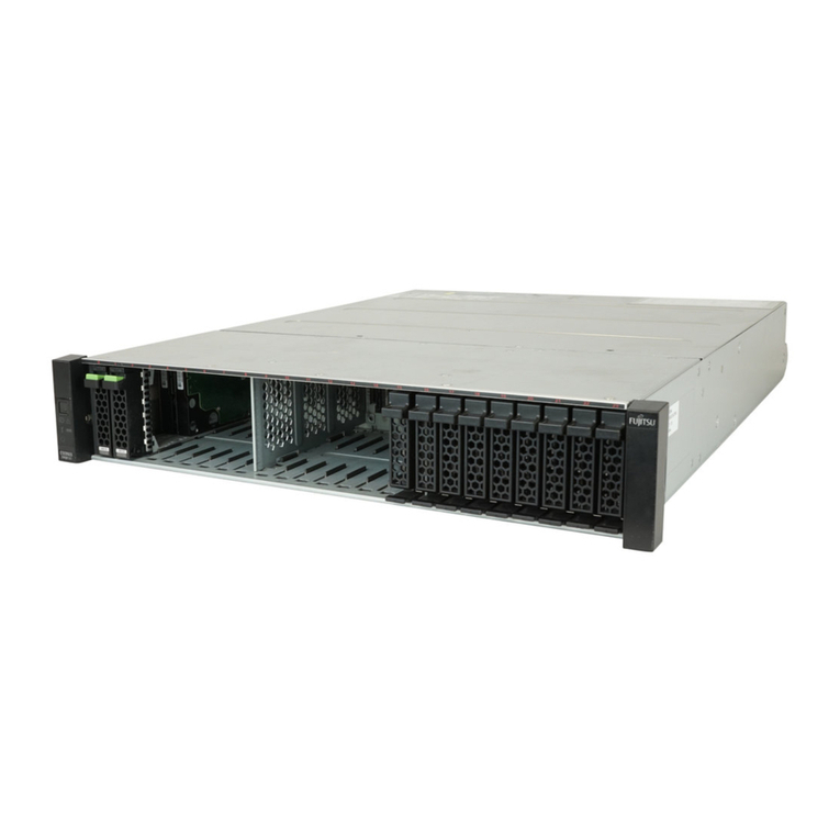
FUJITSU Storage ETERNUS LT140 Tape Library User’s Guide -Site Planning-
Copyright 2018 FUJITSU LIMITED P3AG-3712-01ENZ0
8
List of Figures
Figure 1.1 Base Module front view............................................................................................................................... 11
Figure 1.2 Base Module rear view ................................................................................................................................ 12
Figure 1.3 Rear view of LTO-6 HH SAS (Product ID: LT14ASKE, LT14ASKL),
Rear view of LTO-7 HH SAS (Product ID: LT14ASME, LT14ASML),
Rear view of LTO-8 HH SAS (Product ID: LT14ASNE, LT14ASNL) ................................................................... 13
Figure 1.4 Rear view of LTO-6 HH FC (Product ID: LT14AFKE, LT14AFKL),
Rear view of LTO-7 HH FC (Product ID: LT14AFME, LT14AFML),
Rear view of LTO-8 HH FC (Product ID: LT14AFNE, LT14AFNL) ..................................................................... 14
Figure 1.5 Library controller (Base Module/Expansion Module)................................................................................... 15
Figure 1.6 Power supply unit (PSU).............................................................................................................................. 16
Figure 2.1 Maintenance area ....................................................................................................................................... 21
Figure 2.2 Explanation drawing of the dimensions (top view)..................................................................................... 23
Figure 2.3 Explanation drawing of the dimensions (front view) .................................................................................. 24
Figure 2.4 Mount in the rack ........................................................................................................................................ 24
Figure 2.5 Mount position examples for adapter blocks and rack rails......................................................................... 30
Figure 3.1 Example of a LAN connection...................................................................................................................... 38
Figure 3.2 Direct FC-AL/SAS connection, a single server connection ............................................................................. 40
Figure 3.3 Direct FC-AL/SAS connection, a multiple server connection, a shared library, and
tape drives that are not shared ................................................................................................................... 41
Figure 3.4 FC switch connection, a single server connection ........................................................................................ 42
Figure 3.5 FC switch connection, a multiple server connection, a shared library, and
tape drives that are not shared ................................................................................................................... 43
Figure 3.6 FC switch connection, a multiple server connection, a shared library, and tape drives that are shared ....... 44
Figure 3.7 FC switch connection, a cluster system configuration .................................................................................. 45
