STONEFLY USS-HA User manual

12-bay 2U HA RAID Array
Setup Guide
USS-HA
Unified Storage and Server
Hyperconverged Appliance
© 2023 StoneFly, Inc. | All Rights Reserved
2x 2U HCI Controllers

© 2023 StoneFly, Inc. | All Rights Reserved. P a g e | 1
Copyright © 2006-2023 StoneFly, Inc.
All rights are reserved. No part of this document may be photocopied or reproduced without
the prior written consent of StoneFly.
The information contained in this document is subject to change without notice. StoneFly
shall not be liable for errors contained herein or for consequential damages in connection with
the furnishing, performance, or use of this material.
StoneFly, the StoneFly logo, Storage Concentrator, Integrated Storage Concentrator, ISC,
Modular Storage Concentrator, StoneFly Backup Advantage, StoneFusion, StoneFly
Replicator CDP, ValueSAN, Unified Scale Out, USO, Super Scale Out, SSO, Twin Scale Out,
TSO, Unified Storage & Server, USS, Unified Deduplicated Storage, UDS, Unified Encrypted
Storage, UES, OptiSAN, StoneFly Voyager, DR365, DR365 Fusion, StoneFly Mirroring,
Storage Concentrator Virtual Machine, SCVM, Software-Defined Unified Storage, SDUS,
and StoneFly Cloud Drive are property of StoneFly, Inc.
Other brands and their products are trademarks or registered trademarks of their respective
holders.
Last Updated: 02/2023

StoneFly USS Setup Guide Table of Contents
© 2023 StoneFly, Inc. | All Rights Reserved. P a g e | 2
Contents
1.1 Introduction ..................................................................................................................4
1.1.1 Icons......................................................................................................................5
2.1. Rack Installation Instructions for HCI Controllers.........................................................7
2.2. Rack Installation Instructions for HA RAID Array......................................................10
2.2.1 Safety Reminders.................................................................................................16
1.1 Cabling the Equipment................................................................................................18
3.1.1 Powering On Procedure .......................................................................................22
3.1.2 Powering Down the USS-HA Appliance..............................................................22
4.1 HA RAID Storage Expansion Array IP Address Configuration ...................................25
4.1.1 Serial port setup...................................................................................................26
4.1.2 Web GUI IP Address setup ..................................................................................30
4.2 Configuring IPMI KVM..............................................................................................32
Accessing the IPMI Interface.............................................................................................36
4.3 VMware Management Network Configuration............................................................40
4.3.1 Steps to Configure SCVM Management Port (VMware)......................................48
4.4 Hyper-V Management Network Configuration............................................................51
4.4.1 Steps to Configure SCVM Management Port (Hyper-V)......................................55
4.5 KVM Management Network Configuration ................................................................59
4.6 Steps to Configure SCVM Management Port (KVM)..................................................62
4.7 Configuring the SCVM...............................................................................................65

StoneFly USS Setup Guide Introduction
© 2023 StoneFly, Inc. | All Rights Reserved. P a g e | 3
Chapter-1: Introduction

StoneFly USS Setup Guide Introduction
© 2023 StoneFly, Inc. | All Rights Reserved. P a g e | 4
1.1 Introduction
This document is aimed for system administrators who would like to know how to get started
with StoneFly USS Appliance. It describes initial steps for launching the appliance.
The StoneFly USS is the ideal purpose-built hyperconverged infrastructure solution for
enterprise virtual workloads which allows you to consolidate compute, storage, and networking
into one easy to manage appliance.
This guide gives an overview of the product, rack mounting instructions and initial installation
procedure. Information for using the features of the StoneFusion software is found in the Storage
Concentrator User Guide.
StoneFly Resource Library
The StoneFly SCVM™ Webpage
Each StoneFly USS comes preconfigured with VMware vSphere or Microsoft Hyper-V
hypervisor, a StoneFly SCVM™ Virtual Storage Controller, and an Enterprise Backup Engine
running on a second VM. Additional Virtual Machines can be installed on the USS as needed as
long as adequate processing cores and system memoryare available to support those VMs. Contact
your StoneFly sales representative for details.
USS-HA 2U Controllers with 12-bay RAID Array (with front bezel)

StoneFly USS Setup Guide Introduction
© 2023 StoneFly, Inc. | All Rights Reserved. P a g e | 5
1.1.1 Icons
Icon
Type
Description
Note
Special instructions or information
Warning
Risk of system damage or a loss of data

StoneFly USS Setup Guide Initial Installation
© 2023 StoneFly, Inc. | All Rights Reserved. P a g e | 6
Chapter-2: Initial Installation

StoneFly USS Setup Guide Initial Installation
© 2023 StoneFly, Inc. | All Rights Reserved. P a g e | 7
2.1. Rack Installation Instructions for HCI Controllers
This section provides information on installing the server into a rack unit with the rack rails
provided. There are a variety of rack units on the market, so the assembly procedure may differ
slightly. Refer to the installation instructions that came with your rack.
1. Pull the inner rail out of the slide rail until it clicks.
2. Detach the inner rail completely from the slide rail by pulling the white tab forward
3. After the inner rail is dislodged, adjust the middle rail back to its original position by
pushing the tab on the middle rail.
They rack may tilt and fall due to incorrect installation or placed on
uneven grounds.
The rack must be placed in a flat surface before you begin to slide the
system barebone in for servicing.

StoneFly USS Setup Guide Initial Installation
© 2023 StoneFly, Inc. | All Rights Reserved. P a g e | 8
4. Install the inner rail onto the system barebone. Lock the keyholes and secure the screws.
5. Continue installing the outer rail bracket to the mounting frame. Attach the outer rail
assembling to the frame and press the bracket to fix the rail onto the frame. Repeat to
fully mount the bracket assembly.

StoneFly USS Setup Guide Initial Installation
© 2023 StoneFly, Inc. | All Rights Reserved. P a g e | 9
6. Pull out the middle channel until the ball bearing retainer is locked forward.
7. Slide the release tab and push barebone into rack. Make sure the barebone is completely
installed onto the rack.
Verify ball bearing retainer is locked forward.

StoneFly USS Setup Guide Initial Installation
© 2023 StoneFly, Inc. | All Rights Reserved. P a g e | 10
2.2. Rack Installation Instructions for HA RAID Array
Rack Ear Mount Kit
The following table shows all accessories that came with the rack ear mount kit.
Item
Description
Quantity
01
Mounting bracket assembly, left-side
1
02
Mounting bracket assembly, right-side
1
03
Hexagon washer screws #6-32mm
8
04
Truss head screws M5 x 9.0mm
4
05
M5 cage nuts
4
06
M5 x 25mm
4
07
M6 x 25mm
4
08
#10-32 x 25.4mm
4

StoneFly USS Setup Guide Initial Installation
© 2023 StoneFly, Inc. | All Rights Reserved. P a g e | 11
Installation Procedure
The installation begins with determining the installation position and M5 cage nut (5)
insertion location.

StoneFly USS Setup Guide Initial Installation
© 2023 StoneFly, Inc. | All Rights Reserved. P a g e | 12
Install the fixed rack ear mount to the rear posts and secure them using truss head screws
(4)
With the assistance of another person holding the enclosure at the installation height, the
other person can place four M5 x 25mm (6) at the front of the enclosure and eight #6-32
screws (3), four on each side, to secure the enclosure into the rack.
StoneFly USS Setup Guide Initial Installation
© 2023 StoneFly, Inc. | All Rights Reserved. P a g e | 13
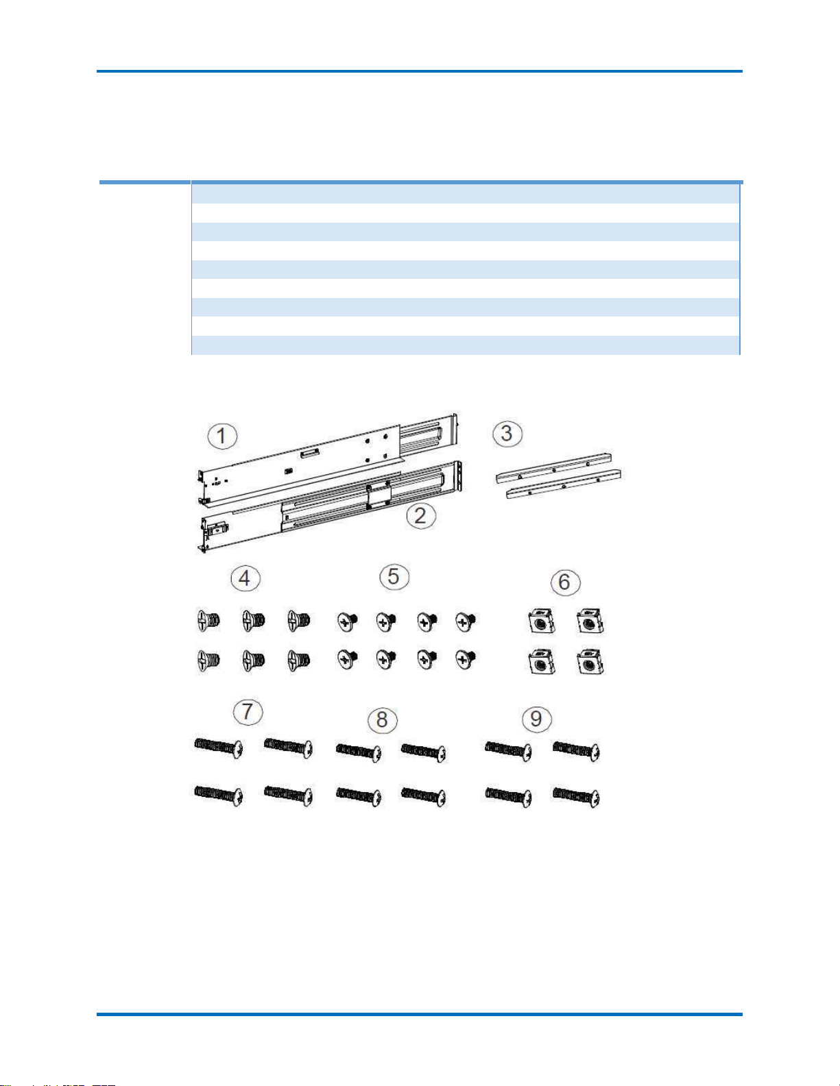
Slide Rail Kit
The following table shows all accessories that came with the slide rail kit.
Item
Description
Quantity
01
Mounting bracket assembly, left-side
1
02
Mounting bracket assembly, right-side
1
03
Inner glides
2
04
Flathead #6-32 L4
6
05
Truss head screws with M5 x 9.0mm
8
06
M5 cage nuts
4
07
M5 x 25mm
4
08
M6 x 25mm
4
09
#10-32 x 25.4mm
4
The installation begins with determining the installation position (front and rear rack
positions) and M5 cage nut (5) insertion location.

StoneFly USS Setup Guide Initial Installation
© 2023 StoneFly, Inc. | All Rights Reserved. P a g e | 14

StoneFly USS Setup Guide Initial Installation
© 2023 StoneFly, Inc. | All Rights Reserved. P a g e | 15
Adjust the length by loosening the four screws on the slide rail. Secure the slide rails to
front and rear posts using truss head screws. Tighten the four screws on the slide to fix
the length.
Attack the inner glides to BOTH sides of the enclosure using flathead screws #6-32 (8)
With the assistance of another person, lift and insert the enclosure onto the slide rail.
Make sure the inner glides on both sides of the enclosure meets the inner glide rail.
Secure the enclosure with M5 or M6 screws from the front.

StoneFly USS Setup Guide Initial Installation
© 2023 StoneFly, Inc. | All Rights Reserved. P a g e | 16
2.2.1 Safety Reminders
If you must relocate the enclosure after installation
Cease all input / output transactions, shut down the system, disconnect all the cables
(please refer to the User Manual for details).
Empty all drive bays (hard drives + hard drive trays) and transport them separately in safe
packaging.
Modules came installed within the enclosure need not be removed.
Follow the instructions provided in the StoneFly Getting Started Guide.
When the system is in operation
1. Module and drive bays must not be empty! They must have a dummy cover / plate in
place to stabilized internal airflow!
2. Should a module fail, leave it in its place until you have the replacement item on-hand to
take its place.
3. Allow at least 18~20cm of clearance space at the rear of the enclosure for ventilation.
4. Avoid touching the PCB and gold-finger connections.

StoneFly USS Setup Guide Cabling Connections and Power Up
© 2023 StoneFly, Inc. | All Rights Reserved. P a g e | 17
Chapter-3: Cabling Connections & Power Up

StoneFly USS Setup Guide Cabling Connections and Power Up
© 2023 StoneFly, Inc. | All Rights Reserved. P a g e | 18
1.1 Cabling the Equipment
The following description shows the steps for two Storage Concentrators, and one HA RAID
Storage Expansion Array. Please make sure that you’ve securely mounted the appliances in the
rack/cabinet before beginning the cabling. It’s also important to note that the power is connected
AFTER all of the data/network connections have been made.
Spanning Tree Protocol (STP) must be disabled on your network switch when using
bonded data ports on the StoneFly USS-HA appliance.
Note: Follow the labels for each port as marked on your appliance(s).
SAS Interconnects –Standard Configuration
Connect the two included Mini-SAS HD cables between each SC and the HA RAID Storage
Expansion Array, as shown below:

StoneFly USS Setup Guide Cabling Connections and Power Up
© 2023 StoneFly, Inc. | All Rights Reserved. P a g e | 19
SAS Interconnects - Multipath Connections (Optional Upgrade)
If you have purchased the optional StoneFly Multipathing Kit, then you will be able to connect
each SC to both RAID controllers on the HA RAID Storage Expansion Array.
The four Mini-SAS HD cables will be connected between each SC and the HA RAID Storage
Expansion Array, as shown below (optional multipathing configuration):
Primary Storage
Controller
Secondary Storage
Controller
HA RAID Array
Table of contents
Other STONEFLY Storage manuals


Popular Storage manuals by other brands

Seagate
Seagate Barracuda 5400.1 ST340015A product manual

Rohde & Schwarz
Rohde & Schwarz SpycerNode2 user manual

Aluratek
Aluratek Tornado AHDUS250F product reference card

Dell
Dell PowerVault MD3220 Series Cli guide

XtendLan
XtendLan XL-RAID-SATA-USB user guide

HP
HP 8505 8mm Cartridge Tape Drive EK-STWCT-UG.... user guide


