Endorphines GHOST User manual
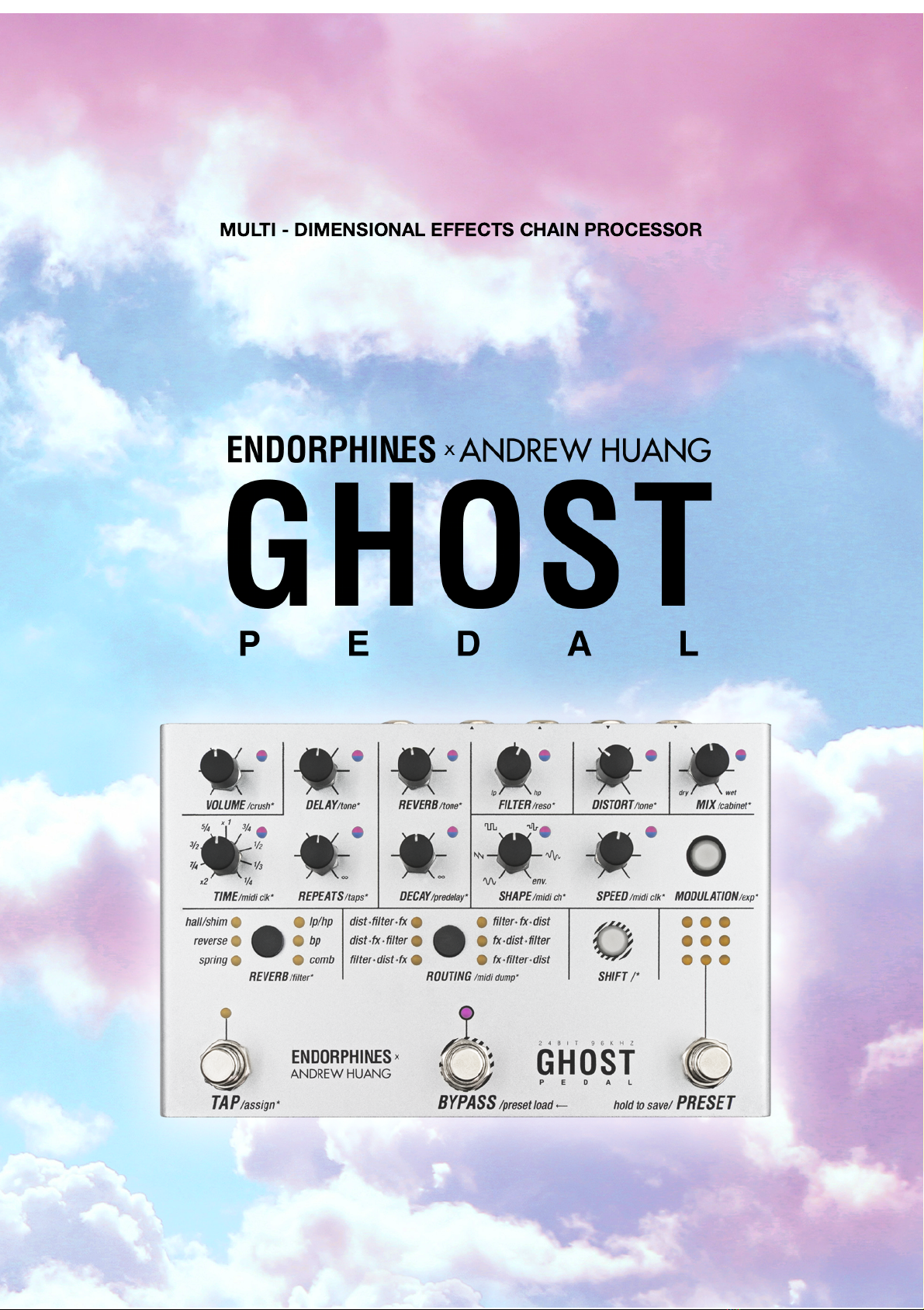
MULTI - DIMENSIONAL EFFECTS CHAIN PROCESSOR

CONTENT
WARRANTY 3
VISIT US 3
INTRO 4
CONNECTING THE POWER 4
TECHNICAL SPECIFICATIONS 4
INTERFACE – FRONT PANEL 5
INTERFACE – REAR SIDE 5
VISUALIZING THE REAL TIME VALUES 10
DISTORTED REALITY 10
THREE FLAVORS OF FILTER 11
SPATIAL EFFECTS 12
DELAY 12
REVERB 13
MODULATION ASSIGNMENT 14
EXPRESSION PEDAL ASSIGNMENT 16
TAP FOOTSWITCH ASSIGNMENT 16
BYPASS FOOTSWITCH MODES 17
RESET 17
PRESETS LOAD / SAVE 18
PRESETS DUMP / UPLOAD 19
SETTINGS AUTOSAVE 20
MIDI IMPLEMENTATION CHART 22
FIRMWARE UPDATE 25
CREDITS 26
COMPLIANCE 27
Page 2 of 27

WARRANTY
1-year warranty is guaranteed from the product's purchase date in case of any
manufacturing errors or other functional deficiencies during runtime.
The warranty does not apply in case of:
🠚 damage caused by misuse
🠚 mechanical damage arising from careless treatment (dropping, vigorous shaking,
mishandling, etc.)
🠚 damage caused by liquids or powders penetrating the device
🠚 heat damage caused by overexposure to sunlight or heating
🠚 electric damage caused by improper connecting
The warranty covers replacement or repair, as decided by us. Please contact us via
email for a return authorization before sending anything. Shipping costs of sending
a module back for servicing is paid by the customer.
VISIT US
https://endorphin.es
https://youtube.com/user/TheEndorphines
https://facebook.com/TheEndorphines
https://twitter.com/endorphin_es
https://www.instagram.com/endorphin.es/
https://www.modulargrid.net/e/modules/browser/vendor:167
For technical requests:
support@endorphin.es
For dealer / marketing inquiries:
info@endorphin.es
ENDORPHIN.ES is a registered trademark.
It is doing business as FURTH BARCELONA, S. L. (EU VAT ID: ES B66836487).
Page 3 of 27
INTRO
From earth shaking subharmonics and distorted drones, to angelic shimmer reverbs
and anything in-between, GHOST is a pedal for the adventurous sound designers
and the most demanding guitar and synth players. Immerse yourself and go beyond
the boundaries of what is possible with a conventional guitar or synth pedal.
GHOST PEDAL brings you new possibilities of tone shaping with its state of the art
flexible audio routing chain, allowing you to jump between dimensions with a single
press of a button. An intuitive UI coupled with hands-on control and preset storage
allows you to stay in the now and focus on your performance.
CONNECTING THE POWER
Use a quality 9V ‘Boss’-standard center negative power adapter, typically 500mA.
However the unit may be powered from any 9 to 18V center-positive or
center-negative DC plugs (full protection). Power supply not included.
TECHNICAL SPECIFICATIONS
🠚 Audio input impedance: 100 kΩ (line) / 1 MΩ (instrument)
🠚 Audio output impedance: 100 Ω
🠚 Audio input range: up to +12 dBV, instrument amplification +11dB
🠚 Audio connectors: 1/4 or 6.35mm TS unbalanced, MIDI connectors: DIN-5,
power connector: 2.1mm tip / 5.5mm barrel DC jack
🠚 Bypass options: true-stereo on electromechanical relays, buffered, trails
🠚 Audio I/O: 24 bit, 96 kHz with 32 bit floating point internal processing
🠚 Current draw: 250 mA minimum, 9V (adapter not included)
🠚 Dimensions: 190 mm x 125 mm x 60 mm (7½″ x 5″ x 2 ¹⁄ ″)
🠚 Weight: 640 gram (1.4 lbs)
Page 4 of 27
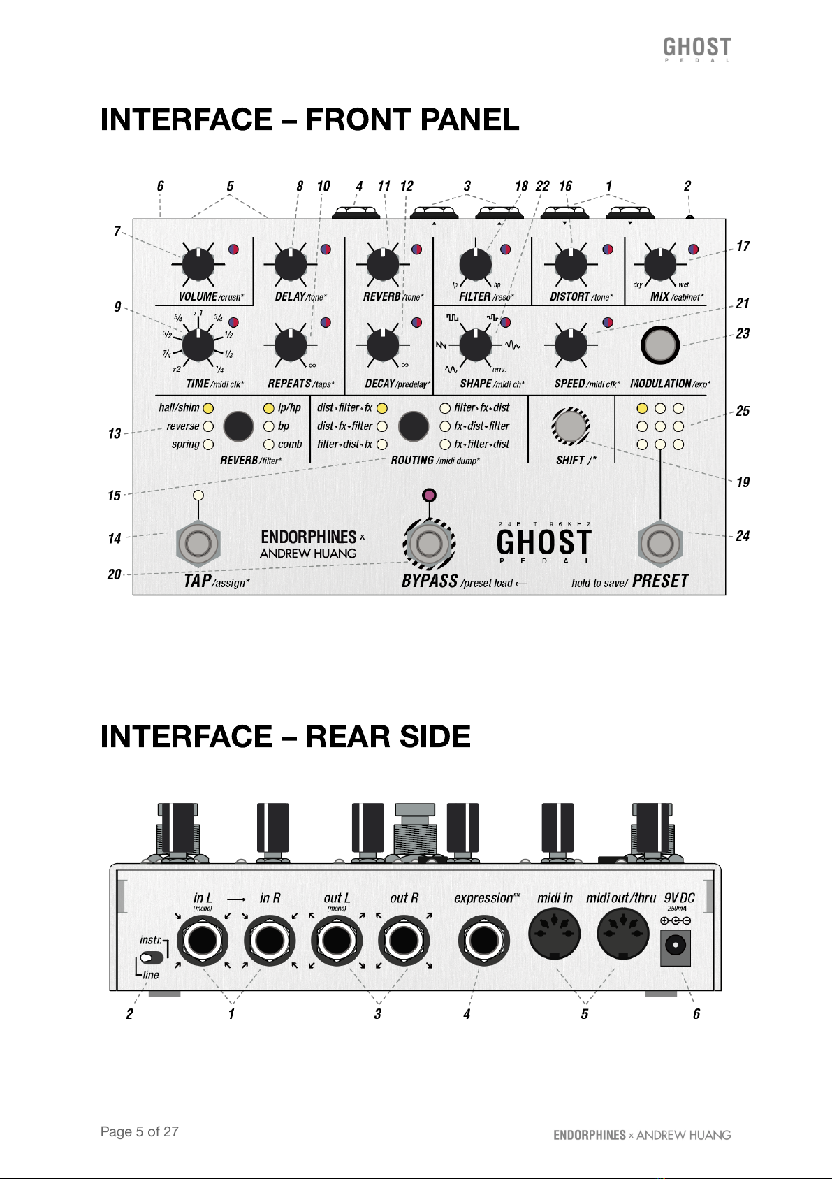
INTERFACE – FRONT PANEL
INTERFACE – REAR SIDE
Page 5 of 27
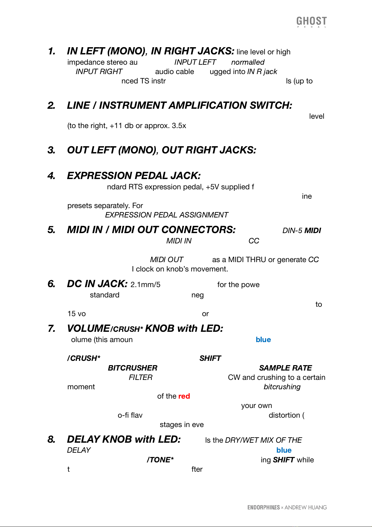
1. IN LEFT (MONO)
,
IN RIGHT JACKS:
line level or high
impedance stereo audio inputs,
INPUT LEFT
– is
normalled
, i.e. pre-routed →
to
INPUT RIGHT
when no audio cable is plugged into
IN R jack
. Accept
standard unbalanced TS instrument 1/4″cables, guitar or line levels (up to
12dBV or +/-2V) with soft clipping introduced with higher audio amplitudes.
2. LINE / INSTRUMENT AMPLIFICATION SWITCH:
select
audio input amplification: line level (to the left, no amplification) or guitar level
(to the right, +11 db or approx. 3.5x gain amplification) to have enough guitar
signal.
3. OUT LEFT (MONO)
,
OUT RIGHT JACKS:
final stereo audio
outputs, accept standard unbalanced TS instrument 1/4″ cables.
4. EXPRESSION PEDAL JACK:
assignable expression pedal input.
Accepts standard RTS expression pedal, +5V supplied from the ring.
Expression pedal morphing macro settings are saved for each of the nine
presets separately. For more details on how to assign the expression pedal
jack check
EXPRESSION PEDAL ASSIGNMENT
section below.
5. MIDI IN / MIDI OUT CONNECTORS:
are standard
DIN-5
MIDI
input and output connectors.
MIDI IN
accepts a list of
CC
values (see MIDI
implementation chart at the end of the manual) on the configured MIDI
channel and MIDI clock.
MIDI OUT
can act as a MIDI THRU or generate
CC
messages and MIDI clock on knob’s movement.
6. DC IN JACK:
2.1mm/5.5mm connector for the power adapter – typical
Boss
® standard, 500mA, +9V, center negative. This jack has internal reverse
protection and voltage rectification therefore accepts any DC adapter of 9 to
15 volts of any polarity – center positive or center negative.
7. VOLUME
/CRUSH*
KNOB with LED:
controls the final output
volume (this amount is shown with the brightness of the
blue
LED brightness:
fully lit shows 100% volume (by default) and fully off - silence). Secondary
/CRUSH*
function (pressing or holding
SHIFT
while turning the knob)
enables the
BITCRUSHER
, or in other words: lowers the
SAMPLE RATE
amount out of the
FILTER
chain: full 96 kHz at CCW and crushing to a certain
moment until the audio falls down to noise. The amount of
bitcrushing
is
shown with the brightness of the
red
LED. When turning this feature, it
radically brings aliasing to the audio signal – use on your own discretion to
creatively add lo-fi flavor. Bitcrusher always stands after the distortion (16)
with cabinet simulator (17*) stages in every routing.
8. DELAY KNOB with LED:
controls the
DRY/WET MIX OF THE
DELAY
effect (that amount is shown with the brightness of the
blue
LED
brightness). Secondary
/TONE*
function (pressing or holding
SHIFT
while
turning the knob) adjusts the tilt EQ after the WET output of the delay chain
Page 6 of 27
(the amount is shown with brightness of the
red
LED), which is useful to
enhance the delays or for dub-delays.
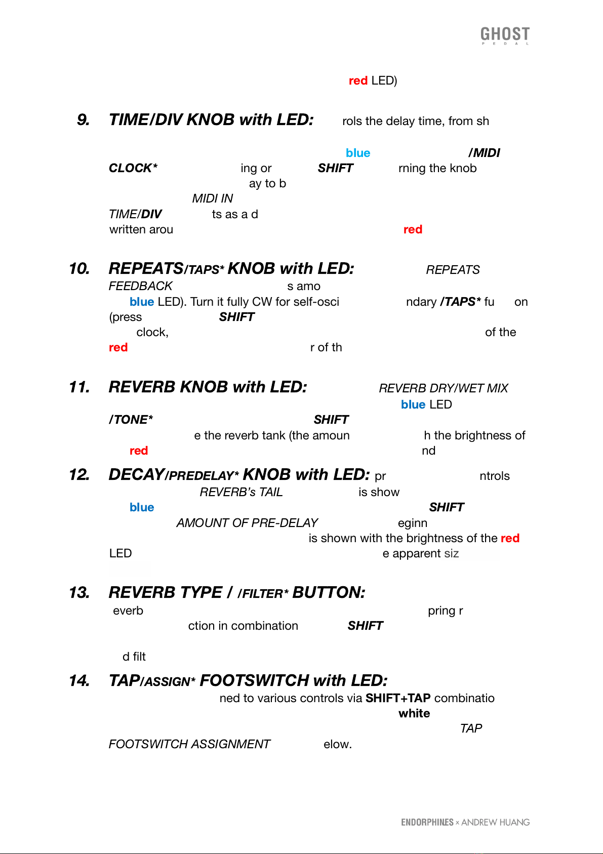
9. TIME/DIV KNOB with LED:
controls the delay time, from short
audio rate repeats CCW and longer taps CW as a primary parameter (the
amount is shown with the brightness of the
blue
LED). Secondary
/MIDI
CLOCK*
function (pressing or holding
SHIFT
while turning the knob from
noon CW) enables the delay to be synchronized to an external MIDI clock
received at the
MIDI IN
connector (5). While the external clock is enabled,
TIME/
DIV
knob acts as a divider / multiplier for the clock with the dividers
written around the knob on the panel and LED flashes
red
according to the
external clock speed.
10. REPEATS
/TAPS*
KNOB with LED:
controls the
REPEATS
or
FEEDBACK
level of the delay (this amount is shown with the brightness of
the
blue
LED). Turn it fully CW for self-oscillation. Secondary
/TAPS*
function
(pressing or holding
SHIFT
while turning the knob in 3 sectors from CCW to
11 o’clock, 11 to 14 o’clock and 14 to full CW shown with brightness of the
red
LED) changes the stereo behavior of the taps produced by the delay (see
DELAY section below).
11. REVERB KNOB with LED:
controls the
REVERB DRY/WET MIX
level (that amount is shown with the brightness of the
blue
LED). Secondary
/TONE*
function (pressing or holding
SHIFT
while turning that knob) adjusts
the tilt EQ before the reverb tank (the amount is shown with the brightness of
the
red
LED) which is useful to get rid of the boomy low-end
12. DECAY
/PREDELAY*
KNOB with LED:
primary function controls
the decay of the
REVERB’s TAIL
(that amount is shown with the brightness of
the
blue
LED). Secondary function in combination with the
SHIFT
button
controls the
AMOUNT OF PRE-DELAY
- time of the beginning of the first
reflections of the reverb (the amount is shown with the brightness of the
red
LED). Amount of pre-delay may be perceived as the apparent size of our
‘space’.
13. REVERB TYPE /
/FILTER*
BUTTON:
primary function selects the
reverb algorithm between: hall with shimmer, reverse and spring reverbs.
Secondary function in combination with the
SHIFT
button switches the filter
algorithms: bipolar SVF LP/HP, BANDPASS or COMB filter. Selected reverb
and filter types shown with the columns of LEDs.
14. TAP
/ASSIGN*
FOOTSWITCH with LED:
multi-function foot
switch, can be assigned to various controls via
SHIFT+TAP
combination. By
default assigned to the TAP tempo of the DELAY and
white
TAP LED blinks
according to the delay clock. For more details on modes see the
TAP
FOOTSWITCH ASSIGNMENT
section below.
Page 7 of 27

15. ROUTING BUTTON:
routing chain switching. Each press cycles
through six different orders of audio effects (see
DISTORTED REALITY
paragraph below).
16. DISTORTION KNOB with LED:
control over the distortion amount
(shown with the brightness of the
blue
LED). Secondary function in
combination with the
SHIFT
button controls the amount of treble content
after the distortion output. Acts as a 6db/oct
TILT EQ
for low and high
frequencies: clean in the middle (default value), CCW settings being darker
and higher CW settings being brighter (this amount is shown with the
brightness of the
red
LED).
17. MIX
/CABINET*
KNOB:
primary function controls the
GLOBAL
DRY/WET MIX
between the clean input at full CCW and the final processed
audio chain output before the
VOLUME KNOB
(7) at full CW (this amount is
shown with the brightness of the
blue
LED). Secondary function in
combination with the
SHIFT
button controls the amount of
SPEAKER
CABINET (or COMBO-) SIMULATOR
applied from clean audio path at CCW
to full at CW (amount is shown with the brightness of the
red
LED). Cabinet
simulator has a set of filters to quickly sculpt a distorted tone signal from your
guitar without the need for extra amps or pedals. Cabinet simulator always
stands after the distortion stage (16) before the bitcrusher stage (7*) in every
routing.
18. FILTER
/RESONANCE*
KNOB:
primary function controls the
FILTER
CUTOFF FREQUENCY
(the amount is shown with the brightness of the
blue
LED). Secondary function in combination with the
SHIFT
button controls the
RESONANCE
of the filter (the amount is shown with the brightness of the
red
LED). When the BAND-PASS filter is selected (13), this knob defines the
width of the band. In
COMB FILTER
mode the resonance knob is bipolar and
defines the feedback, adding negative (to CCW) and positive (CW) combs
and at maximum side CW/CCW values enables the resonator.
19. SHIFT /* BUTTON with LED:
adjusts secondary parameters while
held down and when using other controls (shift functions are labeled with
asterisk
/…*
on the panel). When the shift is enabled, its
white
LED is on and
you may see all the LEDs near the knobs switch from blue to red, showing
visually the amount of secondary parameters with their brightness and
allowing you to edit them (or assign modulation as well!).
SHIFT
button has
an additional latched action, so you may press it once to leave enabled and
adjust other parameters while operating with one hand only, however, some
rarely used settings like bypass types or tap assignments require the
SHIFT
button to be held. After you press and hold
SHIFT
, tweak some parameters
and release the button - it turns that button action off.
20. BYPASS
/PRESET LOAD
FOOTSWITCH:
is essentially a
BYPASS
/
enable / activate effect / on footswitch. Each consequent press enables and
Page 8 of 27
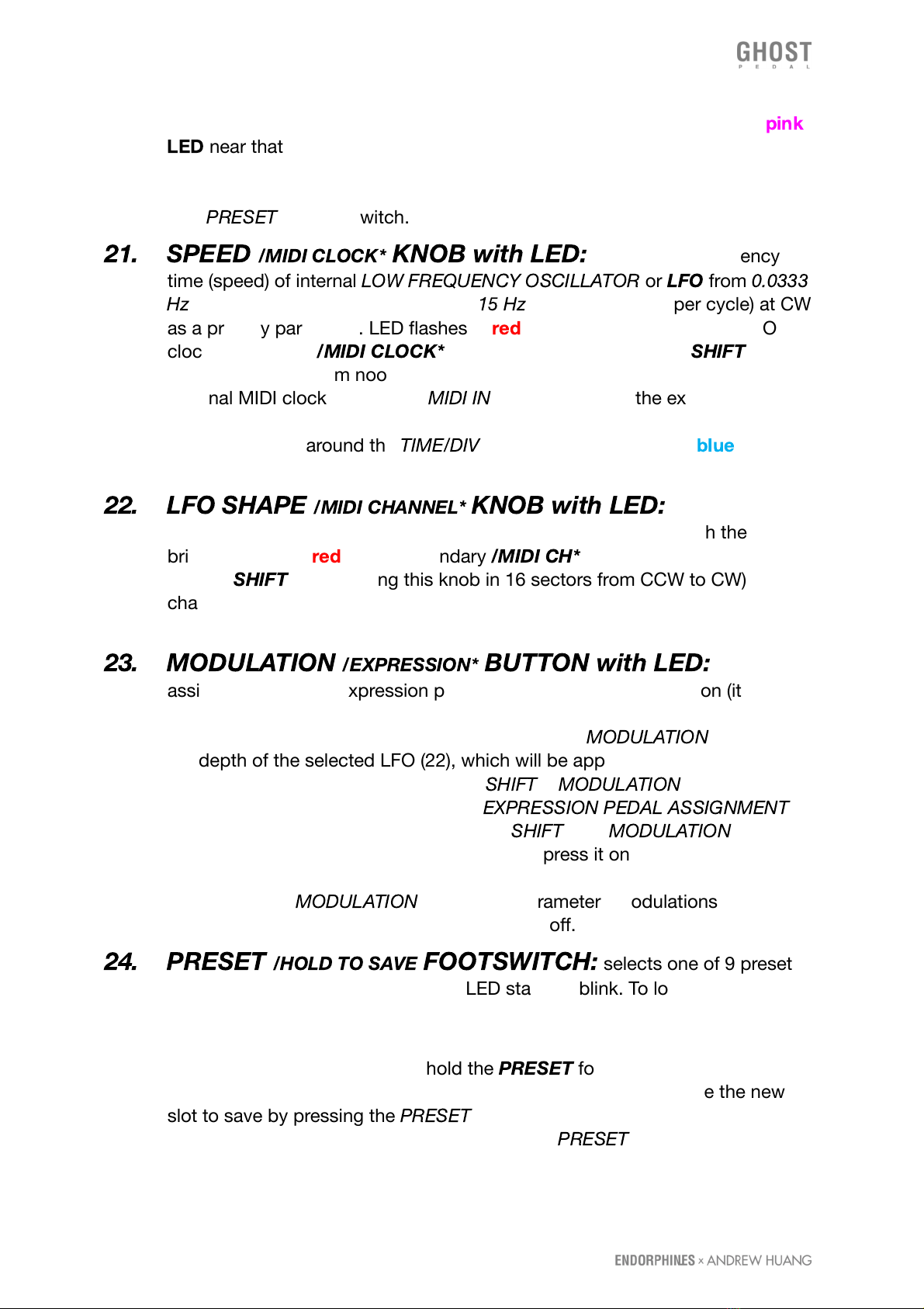
disables the whole effects chain. When the effects chain is enabled, the
pink
LED
near that footswitch is ON. When the effect chain is bypassed, the LED
is off and also all the remaining LEDs except the preset selection LEDs are
dimmed. Additionally is used to confirm the load of the newly selected preset
with
PRESET
(24) footswitch.
21. SPEED
/MIDI CLOCK*
KNOB with LED:
controls the frequency
time (speed) of internal
LOW FREQUENCY OSCILLATOR
or
LFO
from
0.0333
Hz
(30 seconds per cycle) at CCW to
15 Hz
(0.0666 seconds per cycle) at CW
as a primary parameter. LED flashes in
red
LED according to internal LFO
clock. Secondary
/MIDI CLOCK*
function (pressing or holding
SHIFT
while
turning this knob from noon CW) enables the LFO SYNCHRONIZATION to an
external MIDI clock received at
MIDI IN
connector (5). In the external clock
mode this knob acts as a divider / multiplier for the clock with the divisors
similar to values around the
TIME/DIV
knob (9) and LED flashes
blue
according to the external MIDI clock speed.
22. LFO SHAPE
/MIDI CHANNEL*
KNOB with LED:
gradually
selects the LFO shape from the list below (the amount shown with the
brightness of the
red
LED). Secondary
/MIDI CH*
function (pressing or
holding
SHIFT
while turning this knob in 16 sectors from CCW to CW)
changes the MIDI channel from 1st to 16th that the pedal accepts and sends
the MIDI data on.
23. MODULATION
/EXPRESSION*
BUTTON with LED:
used to
assign LFO (22) and expression pedal (4). While holding this button (it will
light up) tweak any of the knobs. The amount by which you tweak this knob
from center position to the sides while holding the
MODULATION
button sets
the depth of the selected LFO (22), which will be applied to the assigned
parameter. Secondary combination of
SHIFT
+
MODULATION
will set the
expression pedal (4) morphing (see 4.
EXPRESSION PEDAL ASSIGNMENT
below for assigning procedure). Same as
SHIFT
(19),
MODULATION
button
has an additional latched action, so you may press it once to leave enabled
and adjust other parameters while operating with one hand only. After you
press and hold
MODULATION
, add some parameters modulations and
release the button - it turns that button action off.
24. PRESET
/HOLD TO SAVE
FOOTSWITCH:
selects one of 9 presets
(25). Once you select the preset, its LED starts to blink. To load that preset
you have to confirm it with the BYPASS footswitch (20). Loading the presets
will not alter current bypass effect state on or off.
To save the preset you have to hold the
PRESET
footswitch for longer than 3
seconds. One of the 9 slots will start to blink and you may choose the new
slot to save by pressing the
PRESET
footswitch a few times. To confirm the
preset save in the selected slot press and hold
PRESET
(20) footswitch for
longer than 3 seconds.
Page 9 of 27
🠚 when
SHIFT
button is enabled, pressing the
PRESET
(20) footswitch will
select the presets in the reverse direction.
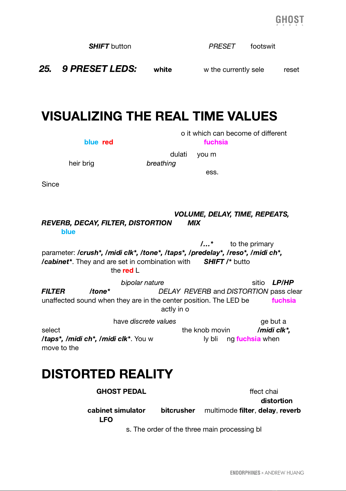
25. 9 PRESET LEDS:
nine
white
LEDs show the currently selected preset
slot and blink when you select the new one without activating it yet.
VISUALIZING THE REAL TIME VALUES
You may notice each knob has an LED next to it which can become of different
brightness of
blue
,
red
or a mixture of both colors -
fuchsia
.
When you change the preset or apply modulation you may see those LEDs will
change their brightness or will be
breathing
. Those are real time parameter’s change
visualization while the physical knobs remain motionless.
Since each knob may set various parameters: primary, secondary and modulation
depth, the current physical knob position may not always reflect its real parameter
value. That’s where the LEDs come to help.
Primary parameters are written in capitals:
VOLUME, DELAY, TIME, REPEATS,
REVERB, DECAY, FILTER, DISTORTION
and
MIX
are shown with the brightness
of the
blue
LED.
Secondary parameters are labeled with an asterisk
/…*
next to the primary
parameter:
/crush*, /midi clk*, /tone*, /taps*, /predelay*, /reso*, /midi ch*,
/cabinet*
. They and are set in combination with the
SHIFT /*
button and are shown
with the brightness of the
red
LED.
Some parameters have a
bipolar nature
with an important center position:
LP/HP
FILTER
and all
/tone*
controls of the
DELAY
,
REVERB
and
DISTORTION
pass clear
unaffected sound when they are in the center position. The LED becomes
fuchsia
when that certain parameter stands exactly in or crosses the center value.
Also some parameters have
discrete values
: i.e. not a continuous change but a
selection of a few parameters placed around the knob moving range:
/midi clk*,
/taps*, /midi ch*, /midi clk*
. You will see LED shortly blinking
fuchsia
when we
move to the next settings from the list.
DISTORTED REALITY
The power of the
GHOST PEDAL
lies in its stereo complex audio effect chain with
96kHz, 32-bit internal audio processing, consisting of 8x oversampled
distortion
algorithm with
cabinet simulator
and
bitcrusher
, a multimode
filter
,
delay
,
reverb
and a modulator -
LFO
. All the knobs positions and settings can be saved and
recalled from 9 presets slots. The order of the three main processing blocks -
Page 10 of 27
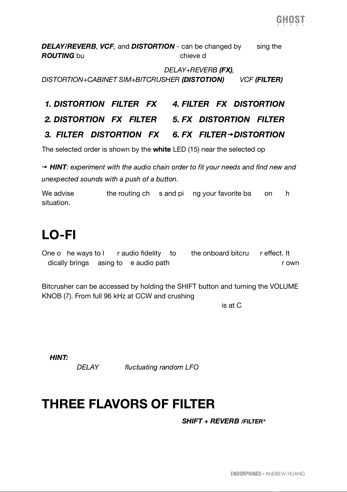
DELAY/REVERB
,
VCF
,
and
DISTORTION
- can be changed by pressing the
ROUTING
button (15), letting you instantly achieve different flavors of sound.
There are six all possible orders for the
DELAY+REVERB
(FX)
,
DISTORTION+CABINET SIM+BITCRUSHER
(DISTOTION)
and
VCF
(FILTER)
blocks:
1. DISTORTION
🠚
FILTER
🠚
FX
2. DISTORTION
🠚
FX
🠚
FILTER
3. FILTER
🠚
DISTORTION
🠚
FX
4. FILTER
🠚
FX
🠚
DISTORTION
5. FX
🠚
DISTORTION
🠚
FILTER
6. FX
🠚
FILTER
🠚
DISTORTION
The selected order is shown by the
white
LED (15) near the selected option.
🠚
HINT
: experiment with the audio chain order to fit your needs and find new and
unexpected sounds with a push of a button.
We advise exploring the routing chains and picking your favorite based on each
situation.
LO-FI
One of the ways to lower audio fidelity is to use the onboard bitcrusher effect. It
radically brings aliasing to the audio path the more we turn it up – use on your own
discretion creatively to add lo fi flavor.
Bitcrusher can be accessed by holding the SHIFT button and turning the VOLUME
KNOB (7). From full 96 kHz at CCW and crushing to a certain moment until the
audio falls apart to noisy clicks and buzzes. Default value is at CCW (clean signal).
The bitcrusher is placed after the distortion (16) with cabinet simulator (17*) stages.
Bitcrusher allows to obtain interesting vowel sounds in ROUTING (15) types when
distortion is placed after the filter: modulating the filter cutoff with high resonance
and applying the bitcrusher effect after.
🠚
HINT:
another trick to to add lo-fi flavor to your audio is to slowly modulate the
time of the
DELAY
(9) with
fluctuating random LFO
(22). That will create a flutter
effect simulating a wobbly tape playback.
THREE FLAVORS OF FILTER
To switch the filter type you simply press the
SHIFT + REVERB
/FILTER*
button (13).
There are three filter types to choose with:
Page 11 of 27
🠚 Bipolar
LP-HP
zero-delay feedback
12db/oct
state-variable filter aka
isolator:
opens from LP silence at CCW to clean unprocessed sound at noon and closes
smoothly in HP silence at CW
🠚
BAND-PASS
12db/oct
state-variable bypass filter (
BPF
) with resonance control
setting the band-width
🠚
COMB
filter with resonator at high resonance settings. Creates
phaser
-alike
effects especially when slightly modulated.
Comb filter is capable of self-oscillation at full CW or CCW
RESONANCE
settings.
/
RESONANCE*
knob (18*) behavior in Comb filter is special: it is bipolar, so from
noon (zero resonance) it either adds negative (CCW) or positive combs (CW).
SPATIAL EFFECTS
This chain of audio effects
(a.k.a.
FX
)
consists of a delay which is then routed into
the reverb with mid/side widener.
DELAY
The delay can be synchronized externally via
MIDI CLOCK
applied from
MIDI IN
CONNECTOR
(5), or by using the onboard
TAP TEMPO footswitch
(14), with
maximum delay time of 2,5 seconds. Three configurations of delay taps are
available, toggled between by holding the
SHIFT + REPEATS
/TAPS*
knob. Delay tap
configurations are
RLRL, LRRL,
and
STEREO
mode – also known as true stereo,
where taps will appear at
OUT 1 or OUT 2
only if something is present at
IN 1
or
IN
2
respectively. Delay can be looped by infinitely recirculating its audio buffer by
setting the
TAP
(14) footswitch to mode 2. Secondary
/TAPS*
function (pressing or
holding
SHIFT
while turning the knob in 3 sectors from CCW to 11 o’clock, 11 to 14
o’clock and 14 to full CW shown with brightness of the
red
LED) changes the stereo
behavior of the taps produced by the delay. Available delay tap configurations are:
🠚
RLRL:
left and right summed aka Ping Pong, taps 2 and 4 hard-panned left, taps
1 and 3 hard panned right (LED in
red
, but fully off, is a default taps mode). In that
mode
LEFT OUTPUT JACK
(3) is a true mono output.
🠚
LRRL:
left and right summed, their taps 1 and 4 hard-panned left, taps 2 and 3
hard panned right (LED in
red
semi-on)
Page 12 of 27
🠚
STEREO:
left and right inputs tap independently in their corresponding left and
right outputs. In this mode the total delay time is halved (LED in
red
fully on).
BUFFER CLEAR.
When using long delay times it may be desirable to clear the
delay buffer in order to quickly introduce new audio material into the delay line. To
do so, turn both the
DELAY
(8) and
REPEATS
(10) knobs to their full CCW positions
to delete the buffer content.
LOOPER.
When
TAP
footswitch (14) is assigned for delay
‘freeze’
(see
TAP
FOOTSWITCH ASSIGNMENT
below), it activates and deactivates delay
LOOPER -
i.e. infinitely recirculating delay’s audio buffer. When the looper is enabled, incoming
into delay
dry
audio signal is turned off enabling the looped part to be played purely.
You may still blend a clean signal to it with a
MIX
knob (17).
🠚
NOTE:
Tap tempo via the
TAP
footswitch (14) doesn’t work if an external MIDI
clock is applied.
REVERB
There are three very different reverb algorithms:
🠚 Lush stereo
HALL REVERB
that adds shimmer after the Dry/Wet control is
turned beyond 60%. Additional controls such as
TONE
and
PREDELAY
(12) can be
accessed by pressing the SHIFT button and turning either the
Reverb Dry/Wet
(11)
or
Reverb Decay
(12) knob respectively. This HALL REVERB can be frozen by
setting the
TAP FOOTSWITCH
(14) to mode 3.
🠚 Whooshing
REVERSE REVERB
. By default the
PREDELAY
amount is set to
maximum and is reversed, meaning that if predelay is set to fully CCW then the pre
delay value is at its maximum. Predelay controls reverse time (length of the buffer
that is being reversed), the bigger the predelay value the more of the reverse effect
you will hear. Shimmer effect can be added to the REVERSE REVERB by setting the
TAP FOOTSWITCH
(14) to mode 3.
🠚 Vintage
SPRING REVERB
with spring excite functionality that can be activated
by setting the
TAP
footswitch (14) to mode 3.
MID/SIDE
widener stays after the reverb and increases the stereo field
simultaneously with the amount of Reverb
DECAY
knob (12). This feature is best
audible on true stereo signals processed with the GHOST.
Page 13 of 27
MODULATION ASSIGNMENT
You can assign a movement to literally any knob or as many knobs you like in a
desired amount directly or inverted. Applied modulation then sums up in its depth
with the manual knob value (a.k.a.
offset
) along with the expression pedal min-max
settings.
The LFO can be synchronized to external
MIDI CLOCK
applied from
MIDI IN
CONNECTOR
(5) by pressing or holding
SHIFT
while turning
SPEED
/MIDI
CLOCK*
knob from noon CW. When an external MIDI clock is enabled this knob
acts as a divider / multiplier for the clock with the divisors similar to values around
the
TIME/DIV
knob (9) and LED flashes
blue
according to the external MIDI clock
speed.
🠚
NOTE: MIDI STOP
and further
MIDI PLAY
message will restart the LFO cycle
when it is synchronized to the external MIDI clock.
The
SPEED
or frequency of internal
LFO / MODULATOR
can be set from 0.0333
Hz (30 seconds per cycle) at CCW to 15 Hz (0.0666 seconds per cycle) at CW.
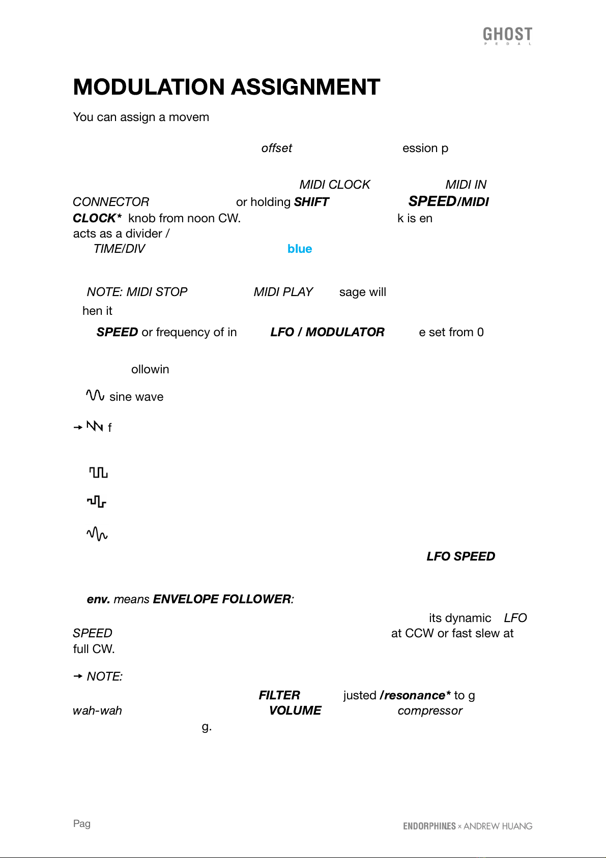
There are following LFO shapes available:
🠚 sine wave
🠚 falling sawtooth ramp (becomes rising sawtooth rap with applied inverted
modulation)
🠚 square wave
🠚 sample & hold wave
🠚 is a fluctuating random wave, inspired by the Source of Uncertainty
TM
generators in modular synthesizers. With this shape the selected
LFO SPEED
knob
(21) sets the probable rate of random change.
🠚
env.
means
ENVELOPE FOLLOWER
:
instead of a cycling wave, a modulation
contour shape is extracted from the incoming audio according to its dynamics.
LFO
SPEED
knob (21) acts as a slew rate adjustment with long at CCW or fast slew at
full CW.
🠚
NOTE:
envelope follower can open a totally new world for dynamic modulation
possibilities. Apply it gently to the
FILTER
with adjusted
/resonance*
to get a
wah-wah
effect. Apply it inverted to
VOLUME
to simulate a
compressor
and that’s
just the tip of the iceberg.
Page 14 of 27
TO ASSIGN THE MODULATION
: simply tweak the knobs while holding the
MODULATION
(23) button. Doing the same with SHIFT /* enabled will assign the
modulation to secondary parameters.
The amount by which you tweak a knob from center to side positions while holding
the
MODULATION
button (23) sets the depth of the selected
[LFO] SHAPE
(22),
which will be applied to the assigned parameter.
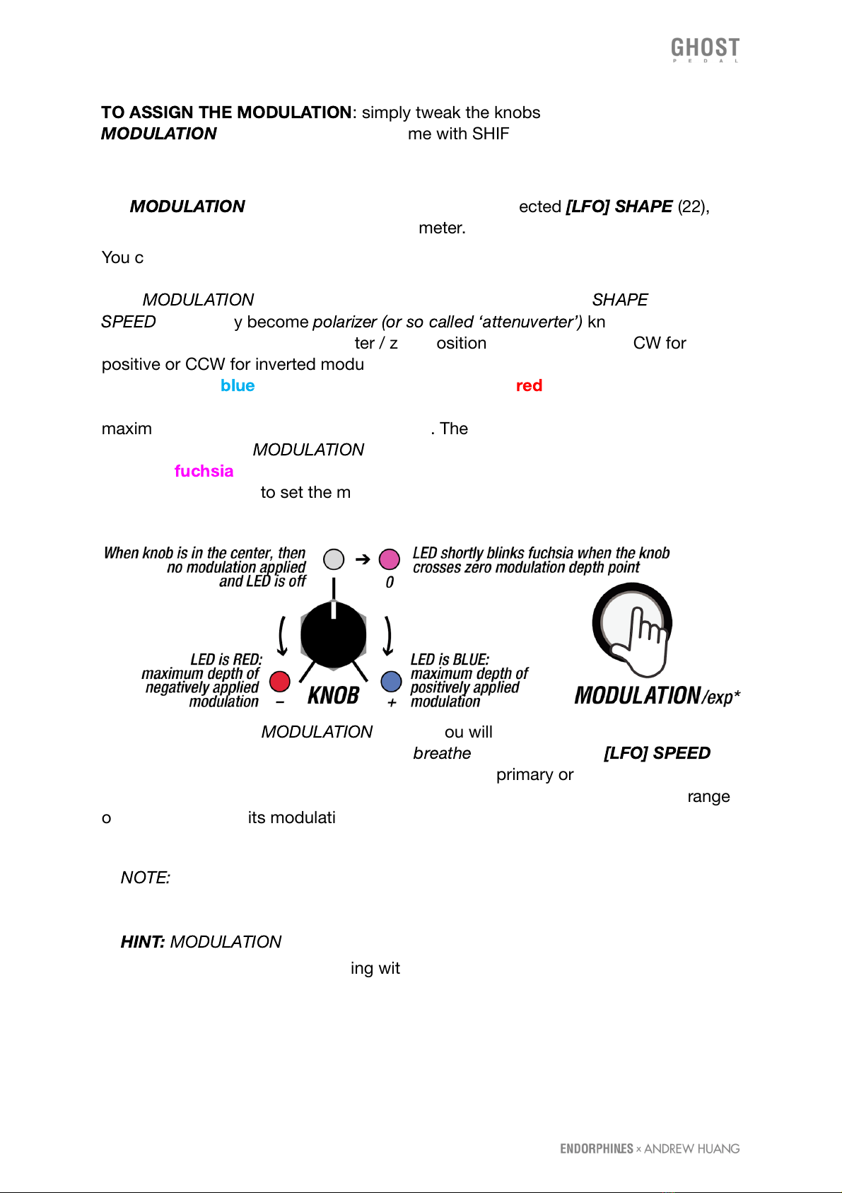
You can apply modulation so the LFO will move the knob from its current position
directly (positive modulation) or inverted (negative modulation). When you hold or
latch
MODULATION
(23) button, all the parameter knobs (except
SHAPE
and
SPEED
) temporary become
polarizer (or so called ‘attenuverter’)
knobs which set
the depth of modulation from center / zero position (no modulation) to CW for
positive or CCW for inverted modulation. Amount of positive modulation depth is
shown with the
blue
and negative modulation with the
red
brightness of the LED
which stands next to the parameter we apply modulation and increases to
maximum when the knob reaches the sides. There is no modulation applied when
the LED is off when
MODULATION
button (23) is active. Parameter LED blinks
shortly in
fuchsia
when the knob crosses the center point - that’s convenient to
know when we want to set the modulation to zero depth.
After you release the
MODULATION
button, you will see the modulation applied with
the LED brightness near the knob - it will
breathe
according to the
[LFO] SPEED
knob (21). You may assign those movements to any primary or certain secondary
parameters to the LFO with various depths. To have the LFO covering the full range
of the knob, adjust its modulation in maximum or minimum (full blue or red) and
then add a manual knob offset.
🠚
NOTE:
you can’t modulate discrete values with LFO (e.g. selecting MIDI
CHANNEL or enabling MIDI SYNC).
🠚
HINT:
MODULATION
(23) button can also be pressed once (latched) so you can
adjust the modulation depth playing with various parameters with one hand.
Page 15 of 27
EXPRESSION PEDAL ASSIGNMENT
To set the expression pedal press
SHIFT + MODULATION
/EXPR*
:
the
MODULATION
button starts flashing slowly. Put the expression pedal in the lower
heel
position (or any initial /
min
position) and set the position of the knobs to their
desired positions. Then press again
SHIFT + MODULATION
/EXPR*
:
MODULATION
button starts flashing fast. We put the expression pedal in the upper
toe
position (or
any other final /
max
position) and set the position of the desired knobs. After, we
exit the expression assign mode by pressing
SHIFT + MODULATION
/EXPR*
third
time and
MODULATION
stops flashing: expression settings are made and saved. If
in one of the positions we put the pedal not fully up or down, then all further side
values have no effect on the parameter. This makes sense when we want to make
the expression pedal start working from, let’s say the middle of the move. Similar to
an expression pedal, all manipulations with the
CC#01
received at
MIDI IN
(5) are
interpreted identically to the expression pedal and vice versa: manipulation with the
pedal sends
CC#01
on the pedal
MIDI OUT
(5).
TAP FOOTSWITCH ASSIGNMENT
Each of the 9 presets has its own assigned
TAP
footswitch (14) destination. By
default it is assigned to the TAP-tempo of the delay (9). The amount of the LED
blinks during
SHIFT + TAP
combo shows the assigned mode:
🠚 one blink (by default) means that the foot switch is assigned to
TAP TEMPO
for setting delay time overriding
TIME/DIV KNOB
(9) setting when internal clock is
enabled and vice versa: when moved,
TIME/DIV KNOB
overrides previously set
TAP
TEMPO
values. The
TAP
LED blinks showing the delay tempo (with both internal or
external delay sync).
🠚
NOTE:
Tap tempo via the footswitch doesn’t work if an external MIDI clock is
enabled.
🠚 two blinks means that the
TAP
footswitch is assigned to enable / disable
the delay's looper (recirculating the delay buffer audio). This feature has a latched
action – meaning that the looper remains enabled after a single press and the LED
remains on. On the next press of the
TAP
footswitch the looper is off and the LED is
off. While the delay looper is ON, the delay clock still blinks on the same LED, but
inverted (turning OFF on each tick of a delay clock).
🠚 three blinks assigns the
TAP
footswitch to influence selected active
reverb function (13): freezing hall reverb (latched action), adding shimmer to reverse
reverb (latched action) or exciting virtual spring reverb (momentary) making it
self-oscillate.
Page 16 of 27
🠚 four blinks assign the
TAP
footswitch to se;lect the
ROUTING
type
as if you press the
ROUTING BUTTON
(15) with a foot.
🠚
NOTE:
only one from four options can be assigned to
TAP
footswitch at a time
(either tap, either delay looper or selected reverb action). You may access all those
functions simultaneously via MIDI (see MIDI implementation chart at the end of the
manual).
BYPASS FOOTSWITCH MODES
There are three bypass options that can be selected by pressing and holding
SHIFT
+ BYPASS
for more than 4 seconds. The number of
SHIFT
button blinks shows the
selected
BYPASS
type:
🠚 one blink (by default):
TRUE BYPASS
means that the stereo relays are
physically connecting audio input jacks to the effects or detaching them from the
effects rerouting to the output jacks directly without any buffers. You may hear
clicks in the pedal inside during relay bypass switching. When the pedal is
unpowered, its bypass is always
true
enabled – meaning it will pass the audio
signals from audio
IN L/R
to audio
OUT L/R
accordingly preserving your tone.
🠚 two blinks:
BUFFERED BYPASS
means that the relays are always on and
we enable/disable effects chain in the DSP code setting the MIX control to CCW.
This type of bypass might be useful if you need a buffered audio input to preserve a
tone or volume amplitude.
🠚 three blinks :
TRAILS BYPASS
means a variation of buffered bypass,
however it keeps the whole effect chain active while the original signal is bypassed.
This type of bypass is useful if you wish to for example have a controlled long
reverb tails or delay still recirculating while the original signal passes clean.
RESET
In case you have tweaked everything so hard you have distorted signal main
outputs, a reset adjusts all advanced / secondary parameters to their default values,
so you may start tweaking from the beginning.
SOFT RESET
: press all four buttons (13) (15) (19) (23) simultaneously and hold them
for more than 3 seconds. Release them once all the LEDs are on and the pedal will
reset the current preset to its default values. Current preset is not saved – you have
to do that manually, otherwise the previously saved preset will be restored from that
slot on the next power up (see
PRESETS LOAD / SAVE
section below)
Page 17 of 27

HARD RESET
: press all four buttons (13) (15) (19) (23) simultaneously and hold
them for more than 10 seconds. Module will erase all its presets to default empty
ones and all the MIDI settings to default as well.
After the module’s reset:
FILTER
,
DELAY’s
,
REVERB’s
and
DISTORTION’s /TONE*
controls are in the middle (no filtering applied);
MIX
and
VOLUME
controls set to
100% (CW value) and cabinet simulator set to 0 (off).
PRESETS LOAD / SAVE
Ghost pedal has 9 preset slots: which correspond to 3x3 LEDs array (25) above the
PRESET
footswitch (24). You may still play with the current preset but only select
the new slot to load. Preset selection and saving is made with the idea to be
operated with one foot only.
TO LOAD A PRESET
🠚 shortly press
PRESET
footswitch (24) a few times to move the blinking LED over
to one of nine slots you wish to load.
🠚 Press
BYPASS
footswitch (20) and the new preset will be loaded. All the
parameters which have continuous changes will slew to the new preset values to
avoid any clicks.
🠚
NOTE:
loading the new preset with a single
BYPASS
footswitch (20) confirmation
will not alter current bypass effect state on or off.
Once you make any changes to the knobs on your GHOST Pedal (see
SETTINGS
AUTOSAVE
section below) you wish to recall later, you have to save them. If the
changes were not saved, you will have a previously saved preset recalled on the
next pedal startup.
TO SAVE THE PRESET
🠚 Hold the
PRESET
footswitch for longer than 3 seconds: one of the 9 slots will
start to blink
🠚 You may choose the new slot to save by shortly pressing the
PRESET
(20)
footswitch a few times.
🠚 To confirm the preset save in the selected slot press and hold
PRESET
footswitch for longer than 3 seconds.
🠚 (1)
NOTE:
when
SHIFT
button is enabled, pressing the
PRESET
footswitch will
select the presets in the reverse direction.
Page 18 of 27

🠚 (2)
NOTE:
there is a blinking LED timeout when you started to load or save a
preset and LED is blinking asking for load confirmation with
BYPASS
or save
confirmation with
PRESET
footswitches - after approximately 15 seconds it will
return to a normal state without any load or save.
PRESETS DUMP / UPLOAD
It is possible to transfer all 9 presets from and to the pedal on either Windows or
Mac computer by using MIDI SysEx dump. This can be done using free software
available for both Mac and Windows.
SYSEX PRESETS DUMP SAVE ON MAC
🠚 Download and install
SYSEX LIBRARIAN
app your Mac:
https://www.snoize.com/sysexlibrarian/
🠚 Connect the
MIDI IN/OUT
ports on the pedal to your Mac via a USB MIDI cable
or by using your midi interface so the
MIDI IN
jack is connected to
MIDI OUT
on
the pedal and
MIDI OUT
jack is connected to
MIDI IN
on the pedal.
🠚 Open SysEx Librarian app and select your MIDI interface from the drop-down
menu list to send a receive SysEx.
🠚 Press
RECORD MANY
and the app will be waiting for the SysEx message to
record.
🠚 To perform a preset dump, hold the
SHIFT
+
ROUTING
buttons for a few
seconds until you see the 9 preset LEDs are on for a moment. You should see the
MIDI data being received inside the SysEx Librarian app so you can save it as a
*.syx file afterwards.
SYSEX PRESET UPLOAD ON MAC
🠚 To upload the presets to the pedal, press the
File
menu in the top menu select
Add to library
in the drop down menu. Select the file you want to transfer from the
list and press
Play
in the top left side of the app. All 9 preset LEDs should light up
on the pedal to confirm the transfer.
Page 19 of 27
🠚 If you are experiencing issues during the preset upload, try adjusting the
Send
MIDI Buffer
inside the Options menu on to 100 msec.
SYSEX PRESETS DUMP SAVE ON WINDOWS
🠚 Download and install
BOME SENDSX
software on your PC computer:
https://www.bome.com/products/sendsx
🠚 Connect the MIDI IN/OUT ports on the pedal to your Mac via a USB MIDI cable
or by using your MIDI interface so the MIDI IN jack is connected to MIDI OUT on the
pedal and MIDI OUT jack is connected to MIDI IN on the pedal.
🠚 Open Bome SendSX software and configure in the top menu the MIDI IN and
MIDI OUT ports to send a receive SysEx to your connected MIDI interface device.
🠚 To perform a preset dump, hold the
SHIFT
+
ROUTING
buttons for a few seconds
until you see the 9 preset LEDs light up. You should see the midi data being
received in the MIDI IN window inside the Bome SendSX software.
🠚 Save the presets on your computer by pressing the
File
menu in the top left
corner of the Bome SendSX and select
Save Midi In As…
in the drop down menu.
SYSEX PRESET UPLOAD ON WINDOWS
🠚 To upload the presets to the pedal, press the
File
menu in the top left corner of
the Bome SendSX and select Open in the drop down menu. Once you have
selected your preset bank file in .syx format, press
Send (F4)
in the lower left side of
the program. All 9 preset LEDs should light up on the pedal to confirm the transfer.
🠚 If you are experiencing issues during the preset upload, try adjusting the Send
MIDI Speed inside the Options menu on Bome Send SX to around 1.29KB/s.
SETTINGS AUTOSAVE
There are a few layers of data and settings GHOST pedal can save and recall on the
next power up cycle. Some of them you may change using the controls of the pedal
and some of them are accessible via MIDI CC# messages (see
MIDI
IMPLEMENTATION CHART
below).
Page 20 of 27
Table of contents
Other Endorphines Music Pedal manuals


