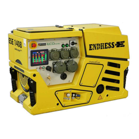
Status at: May 2015 ESE 1408 DBG ES DIN 7
8 Technical specifications ......................................................................................76
9 Replacement parts..........................................................................................................79
9.1 Sound-absorbing hood..........................................................................................79
9.2 Engine alternator and exhaust...............................................................................83
9.3 Generator..............................................................................................................84
*Attention! Line circuit breaker with a characteristic specially adapted to the alternator.
Do not use a line circuit breaker with a standard characteristic........................86
9.4 Accessories and markings.....................................................................................87
List of illustrations
Figure 2-1: Signs on the generator.....................................20
Fig. 3-1: Views of the generator..........................................27
Figure 3-2: Components on the operating and engine side 28
Figure 3-3: Components on the exhaust and generator side
....................................................................................29
Fig. 3-4: Control panel components....................................30
Figure 3-5: Components of the standard accessories.........31
Fig. 3-6: Components of the special accessories................32
Figure 4-1: Actuate manual choke......................................38
Figure 4-2: Standard design of operating panel..................38
Fig. 4-3: Choke on the engine side.....................................40
Figure 4-4: Fuel pump for an emergency start....................40
Fig. 4-5: Connecting up to consumers................................43
Figure 4-6: Check the protective conductor........................44
Figure 4-7: Multi-functional display.....................................45
Fig. 6-1: Replacing the battery............................................67
Fig. 6-2: Oil dipstick............................................................68
Fig. 6-3: Changing the oil ...................................................69
Fig. 6-4: Replacing a fuse...................................................71
Fig. 8-1: Generator dimensions..........................................76
List of tables
Table 2.1: Danger zones and work areas on the generator 19
Table 2.2: Signs on the generator.......................................22
Table 4.1: Test lamp protective conductor..........................44
Table 4.2: FI protection switch test.....................................51
Table 4.3: Insulation monitoring without switching off.........52


