manuals.online logo
Brands
  1. Home
  2. •
  3. Brands
  4. •
  5. Wavetek
  6. •
  7. Portable Generator
  8. •
  9. Wavetek 2500 User manual

Wavetek 2500 User manual

_SIGNAL
GEhJERATOR
MODEL
2500
OPERA]]N~NUAL
THIS
DOCUMENT
CON"iAINS
IN~ORMA"iION
PRC-
PRIETARY
TO
WAVETEK AND
IS
PROVIDED
SOLEL.
Y
FOR
INSTRUMENi
OPERATION
AND
MAINTENANCE. THE
INFORMATION
IN
THIS
DOCUMENT
MAY
NOI
BE
DUPLICATED
IN
ANY MANNER WITHOUT THE
PRIOi1
APPROVAL IN WRITING FROM WAVETEK.
:
Yv'AVETEK
·REV
..
E
USE
OF
THIS
MANUAL
The
documentation
package
for
the
Wavetek
Model
of
an
Operating
Manual
and
a
Service
Manual.
contains
seven
sections.
2500
RF
Signal
Generator
consists
This
is
the
Operating
Manual.
It
Section
1
Section
2
Section
3
section
J;
section
5
Section
6
Section
7
Provides
general
information
about
the
unit,
including
specifications.
Contains
detailed
installation
instructions.
Instructions
proceed
from
the
initial
inspection
(after
unpacking
a
unit)
to
the
instrument
checkout
procedure
after
installation
is
completed.
Provides
operating
instructions
for
the
unit.
Contains
the
performance
tests
used
to·
verify
that
all
functions
of
the
unit
work
properly.
Contains
the
maintenance
instructions
for
the
unit,
including
the
calibration
procedure.
Contains
GPIB
documentation.
Contains
any
changes
that
must
be
made
to
this
manual.
Changes
may
occur
for
various
reasons.
Wavetek's
product
improvement
program
incorporates
the
most
current
technology
into
these
instruments
as
rapidly
as
development
and
testing
will
permit.
Due
to
the
time
required
to
document
and
print
Operating/Service
manuals
it
is
not
always
possible
to
include
information
about
product
improvements
in
the
original
printing
for
a
manual.
Engineering
updates
to
address
these
changes
occur
in
Section
7.
The
Service
Manual
is
an
optional
item.
It
contains
Theory
of
Operation,
Trouble-
shooting
Notes,
Reference
drawings
(schematics
and
assembly),
and
Replaceable
Parts
Lists.
Schematics
and
their
associated
assembly
drawings
are
grouped
together.
Please
note
that
each
of
the
figures
in
this
text
has
a
ten
digit
identification
number
(xxxx-xx-xxxx).
For
example,
the
Wavetek
identification
number
for
Figure
2-1
is
0012-00-0176.
These
numbers
are
for
internal
use
by
Wavetek
only.
DIGITALY REMASTERED
OUT OF PRINT- MANUAL SCAN
S
By
ArtekMedia
P.O. BOX 175
Welch, MN 55089-0175
Phone: 651-269-4265
www.artekmedia.com
“High resolution scans of obsolete technical manuals”
If you are looking for a quality scanned technical manual in PDF format please visit our WEB
site at www.artekmedia.com or drop us an email at manuals@artekmedia.com
If you don’t see the manual you need on the list drop us a line anyway we may still be able to
obtain the manual you need or direct you to other sources. If you have an existing manual you
would like scanned please write for details. This can often be done very reasonably in
consideration for adding your manual to our library.
Typically the scans in our manuals are done as follows;
1) Typed text pages are typically scanned in black and white at 300 dpi.
2) Photo pages are typically scanned in gray scale mode at 600 dpi
3) Schematic diagram pages are typically scanned in black and white at 600
dpi unless the original manual had colored high lighting (as is the case for
some 70’s vintage Tektronix manuals).
4) Most manuals are text searchable
5) All manuals are fully bookmarked
All data is guaranteed for life (yours or mine …whichever is shorter). If for ANY REASON your
file becomes corrupted, deleted or lost, ArtekMedia will replace the file for the priceof shipping,
or free via FTP download.
Thanks
Dave & Lynn Henderson
ArtekMedia
CONTEl.'TS
SECTION
1 -
GENERAL
INFORMATION
1.1
INTRODUCTION
1.2
SPECIFICATIONS
SECTION
2 -
INSTALLATION
INSTRUCTIONS
2.1
INTRODUCTION
2.2
INITIAL
INSPECTION
2.3
MECHANICAL
INSTALLATION
2.04
ELECTRICAL
INSTALLATION
2.5
INSTALLATION
CHECKS
SECTION
3 -
OPERATING
INSTRUCTIONS
3.1
INTRODUCTION
3.2
AIR
FILTER
CAUTION
3.3
FRONT
PANEL
DESCRIPTION
3.04
REAR
PANEL
DESCRIPTION
3.5
LOCAL
MODE
OF
OPERATION
3.5.1
TURN
ON
3.5.2
NUMERIC
ENTRIES
(KEYBOARD
AND
SPIN
KNOB)
3.5.3
NUMERIC
ENTRY
(KEYBOARD
ONLY)
3.5.04
NON-NUMERIC
ENTRY
3.5.5
SETTING
RF
OUTPUT
CHARACTERISTICS
3.5.5.1
FREQUENCY
3.5.5.2
POWER
LEVEL
3.5.5.3
MODULATION
3.5.6
STORAGE/RECALL
OF
FRONT
PANEL
SETTINGS
3.5.7
RETURN
TO
LOCAL
MODE
OF
OPERATION
FROM
REMOTE
(GPIB)
3.6
OPERATOR
ERROR
MESSAGES
3.6.1
UNLOCKED
3.6.2
TRIPPED
3.6.3
MODULATION
DISPLAY
BLINKS
ON/OFF
3.7
CALIBRATION
DUE
INDICATORS
SECTION
4
04.1
04.2
04.3
04.4
4.5
04.6
4.7
4.8
4.9
3.7.1
UNLOCKED
3.7.2
UNLVD
-
PERFORMANCE
TESTS
INTRODUCTION
FREQUENCY
RESOLUTION
AND
RANGE
TEST
FREQUENCY
ACCURACY
TEST
HARMONICS
TEST
NON-HARMONICS
TEST
SUB-HARMONICS
TEST
PHASE
NOISE
TEST
SWITCHING
SPEED
TEST
.AM
PERFORMANCE
TESTS
(AM
ACCURACY,
DISTORTION,
AND
BANDWIDTH)
i
Scans by ArtekMedia => 2011
4.10
4.11
4.12
4.13
4.14
4.15
4.16
4.17
SECTION 5
5.1
5.2
RESIDUAL
AM
TEST
RESIDUAL
PM
TEST
CONTElITS
(Con't)
FM
PERFORMANCE
TESTS
(PM
ACCURACY,
DISTORTION,
BANDWIDTH,
AND
DEVIATION
RANGE)
OUTPUT
POWER
LEVEL
ACCURACY
TEST
OUTPUT
POWER
LEVEL
FLATNESS
TEST
OUTPUT
IMPEDANCE
TEST
EXTERNAL
REFERENCE
TEST
SAMPLE
PERFORMANCE
TEST
RECORD
-
MAINTENANCE
INTRODUCTION
SERVICE
INFORMATION
5.2.1
FAN/AIR FILTER
MAINTENANCE
5.2.2
BOTTOM
COVER
REMOVAL
5.2.3
AIR FILTER
CLEANING
5.3
AUTOCAL~
CALIBRATION
5.4
USER
DIAGNOSTICS
5.5
POWER
UP
TEST
SECTION 6 - GPIB
6.1
INTRODUCTION
6.2
INSTALLATION INSTRUCTIONS
6.3
OPERATING
INSTRUCTIONS
6.3.1
LOCAL/REMOTE
MODE
SELECTION
6.3.2
ADDRESS
SETTING
6.3.3
GPIB INPUT
COMMAND
DEFINITION
6.3.4
GPIB INPUT
COMMAND
TYPES
6.3.5
PARAMETER
COMMANDS
6.3.6
ENUMERATED
COMMANDS
6.3.7
DIRECT
COMMANDS
6.3.8
QUERY
COMMANDS
6.3.9
SAMPLE
SOFTWARE
PROGRAMS
6.4
GPIB
DATA
EXCHANGE
TEST
6.5
GPIB
BOARD
TEST (USER DIAGNOSTIC)
SECTION 7 -
MANUAL
CHANGES
7.1
INTRODUCTION
7.2
MANUAL
CHANGES
ii
Scans by Artekmedia => 2011
Figure
2-1
Figure
3-1
Figure
3-2
Table
4-1
Table
6-1
Table
6-2
Table
6-3
Table
6-4
Table
6-5
Table
6-6
Table
6-7
Table
6-8
LIST
OF
FIGURES
AND
TABLES
AC
Power
Connector
Module
Wavetek
Model 2500
Front
Panel
Wavetek
Model
2500
Rear
Panel
Recommended
Test
Equipment
Parameter
Command
Headers
Engineering
Notation
Enumerated
Command
Listings
Enumerated
Command
Headers
Direct
Command
Headers
Query
Command
Headers/2500
Response
Header
Formats
for
10,
ERR,
and
SET
Error
Messages/Serial
Poll
Byte
iii
Query
Commands
Scans by ArtekMedia => 2011
1.1
INTRODUCTION
The
Wavetek
Model
2500
is
a
micro-
processor
controlled,
single-loop
syn-
thesized
signal
generator
that
covers
the
frequency
range
of
400
kHz
to
1100
MHz.
Standard
features
include
a
very
broad
1
MHz
peak
FM
deviation,
an
exclusive
AutoCal®
self-calibration
function,
extensive
user
diagnostics,
an
automatic
power
up
test
sequence,
and
15
non-volatile
memory
locations.
A
10
MHz
square
wave
reference
output
is
available
at
the
rear
panel.
All
operational
controls
are
located
on
the
front
panel.
Controls
include
keypad
swi
tches
and
a
sp
in
knob
for
entry
of
all
RF
output
numeric
parame-
ters.
The
spin
knob
provides
entry
that
has
the
ease
and
continuity
and
fine
tuning
of
analog
control.
Instrument
settings
are
indicated
on
three
custom
LCD
displays
with
electroluminescent
backlighting.
The
2500
is
a
space-saving
3/4-rack
size.
(Two
optional
rack
mount
adaptor
kits
are
available.)
A
talk/listen
GPIB
fully
conforming
to
the
IEEE-488
standard
is
installed
in
the
Model
2500.
Because
it
also
con-
forms
to
proposed
IEEE
Standard
951,
the
Model
2500
can
be
easily
conformed
to
any
ATE
system.
1.1.1
FREQUENCY
CHARACTERISTICS
The
carrier
frequency
may
be
set
from
0.4
to
1100
MHz
with
a
10
Hz
resolution
and
.00005%
(.5
ppm)
accuracy.
1-1
SECTION
1
GENERAL
INFORMATION
1.1.2
MODULATION
CHARACTERISTICS
The
instrument
features
both
internal
and
external
AM
and
FM
capabilities.
The
internal
modulation
source
may
be
set
at
a
400
or
1000
Hz
rate.
AM
depth
is
specified
from
0
to
99.9%.
FM
de-
viation
can
be
set
from
0 -
500
kHz
f
or
carrier
frequencies
between
137.5
MHz
and
275
MHz
and
from
0
to
1
MHz
at
all
other
carrier
frequencies.
Reso-
lution
is
from
10
Hz
to
1 kHz
depending
upon
the
deviation
set
(see
Section
1.2
for
greater
detail).
The
external
reference
input
may
be
a
sine
or
square
wave
at
1
MHz,S
MHz,
or
10
MHz.
Internal
and
external
sources
may
be
used
simultaneously
to
produce
complex
modulation.
1.1.3
OUTPUT
LEVEL
CHARACTERISTICS
The
Model
2500
has
an
RF
output
range
of
+13
dBm
to
-137
dBm
with
an
output
level
flatness
of
±1
dB.
The
level
resolution
is
.1
dB.
OUtput
level
may
be
read
in
dBm,
mV,
or
~V.
Reverse
power
protection
to
50
watts
is
standard.
1.1.4
AutoCal®/DIAGNOSTICS
The
Model
2500
utiliZes
a
unique
Auto
Cal®
routine
to
perform
a
quick
and
easy
almost
completely
automatic
self-
calibration.
A
key
is
simply
inserted
into
the
key-lock
located
on
the
rear
panel
and
at
turn
on
the
instrument
will
present
the
operator
with
the
first
in
a
series
of
menus
to
perform
the
AutoCal®
routine
or
any
of
the
19
user
diagnostics
supplied
with
the
unit.
Scans by Artekmedia => 2011
1.1.5
STORED
SETTINGS
1.1.6
ERROR
INDICATORS
Nonvolatile
memory
locations
allow
up
to
15
complete
front
panel
settings
to
be
stored
and
recalled
in
any
order.
This
storage
permits
fast
and
accurate
recall
of
frequently
used
settings.
The
parameters
stored
in
location
number
15
may
be
recalled
with
one
keystroke.
The
front
panel
displays
for
the
2500
indicate
the
following
error
condi-
tions:
An
unlocked
condition
in
the
phase
locked
loop
circuitry
An
unleveled
condition
in
the
RF
output
leveler
circuitry
The
2500
powers
up
with
the
same
set-
tings
present
when
power
was
removed,
except
the
RF
output
will
be
off.
A
tripped
RF
circuit
breaker
FM
overmodulation
1.2
SPECIFICATIONS
1.2.1
FREQUENCY
Range
(MHz)
Resolution
Frequency
Stability/Temp
Frequency
Stability
(Aging)
switching
Speed
1.
2 . 2
RF
OUTPUT
Impedance
output
Connector
Calibrated
Level
Range
Level
Resolution
Level
Accuracy
Flatness
Leakage
.4
-
1100
10
Hz
±0.5
ppm
(±.00005~),
0-50
0 C
<1
ppm/yr.
Typically
200
mSec
50Q
Type
"N"
+13
to
-137
dBm
.1
dB
±1.3
dB
for
power
levels
>-36.9
dBm;
±(1.3
dB
+
.1
dB/IO
dB
step
decrease)
for
power
levels
<-36.9
dB
±1
dB
<1
~V
into
a
2-turn
1
inch
diameter
loop
at
1100
MHz
Conforms
to
MIL-STD-461,
Class
E,
Sections
CS01,
CS02,
CS06,
RE02,
RS03
(to
1
GHz);
VDE
0871,
Class
B.
1-2
Scans by ArtekMedia => 2011
1.2.3
SPECTRAL
PURITY
Harmonics
Sub-Harmonics
(550
MHz
-
1100
MHz)
Non-Harmonics
(Spurs)
(>5
kHz
from
carrier)
1.2.4
PHASE
NOISE
@
500
MHz
10
kHz
offset
20
kHz
offset
1.2.5
RESIDUAL
AM
(.05
-15 kHz
PDBW)
1.2.6
RESIDUAL
FM
(.05
-
15
kHz
PDBW)
(.3
- 3 kHz
PDBW)
1.2.7
MODULATION
Modes
Internal
Source
External
Source
1.2.7.1
AM
CHARACTERISTICS
AM
Frequency
Response
AM
Resolution
AM
Range
Modulation
Accuracy,
AM
(0
-
901..)
AM
Distortion
<-30
dBc
<-25
dBc
<-50
dBc
for
carrier
frequencies
<137.5
MHz
<-60
dBc
for
carrier
frequencies
>137.5
MHz
<-107
dBc/Hz
guaranteed
(Typ
-110
dBc/Hz)
Typ
<-115
dBc/Hz
<-65
dBc
<30
Hz
nus
(.4
-
137.49999
MHz)
<15
Hz
rms
(137.5
-
274.99999
MHz)
<30
Hz
rms (275 -
550
MHz)
<60
Hz
rms (>550
MHz)
<15
Hz
rms
typical
(.4
-
137.49999
MHz)
<10
Hz
rms
typical
(137.5
-
274.99999
MHz)
<15
Hz
rms
typical
(275
-
550
MHz)
<30
Hz
rms
typical
(>550
MHz)
AM,
FH,
COMPLEX
(EXT
AM
and
INT
FM·
,
EXT
INT
AM)
FM
400
Hz, 1 kHz;
derived
from
frequency
standard
AM
Mode:
DC
to
20 kHz, 600 Q
floating
input
FM
Mode: 20
Hz
to
100
kHz,
600 Q
floating
input
DC
to
15 kHz (Typ
to
20
kHz),
(3
dB
bw,
501..
modulation)
.11..
and
o - 99.91.. (+3
dBm
max
output
at
99.91..
modulation)
±11..
+
(±51..
of
indicated
setting)
at
internal
rates
<1.51..,
below
301..
modulation
<31..,
30%
to
701..
modulation
<51..,
701..
to
901..
modulation
1-3
Scans by Artekmedia => 2011
1.2.7.2
FM
CHARACTERISTICS
FM
Resolution
FM
Rate
FM
Deviation
Range
for
1 kHz
Rate
Modulation
Accuracy,
FM
FM
Distortion
1.2.8
FRONT
PANEL
CONTROL
10
Hz
(deviations
<10 kHz)
100
Hz
(deviations
<100 kHz)
1 kHz
(deviations
<1
MHz)
20
Hz
-
100
kHz
(3
dB
bw)
1
MHz
peak
(3-137.49999
& >275
MHz)
500
kHz
peak
(137.5
-275
MHz)
100
kHz
peak
(1
-3
MHz)
10
kHz
peak
(.4
- 1
MHz)
At
internal
rates,
±S%
of
indicated
setting,
excluding
residual
FM
<2%
at
internal
rates
for
deviation
<100 kHz
Type
Push-buttons,
Spin-Knob
1.2.9
REVERSE
POWER
PROTECTION
Max
RF Power
50
W
Trip
Level
-
.7
W
Trip
Time
Typically
<1 mSec
Max
DC
Voltage
50
V
1.2.10
STORED
SETTINGS
15
total,
non-volatile;
complete
front
panel
settings
stored
1.2.11
EXTERNAL
REFERENCE
INPUT
(REAR
PANEL)
Frequency
1,
5,
or
10
MHz
Required
Input
Level/Impedance
1-5
Vp-p,
into
50
Q
lNaveform
Sine
or
Square
Wave
1.2.12
INTERNAL
REFERENCE
OUTPUT
(REAR
PANEL)
Frequency
10
MHz
Voltage
Out/Impedance
100
mVp-p,
into
50
Q
Waveform
Square
Wave
1-4
Scans by ArtekMedia => 2011
1.2.13
GENERAL
Dimensions
WoJeight
Power
1.2.14
REMOTE
PROGRAMMING
(GPIB)
Interface
Functions
14
em
(5.5
in.)
High;
31.8
em
(12.5
in.)
Wide;
53.3
em
(21
in.)
Deep
12.57
kg
(27.7
lbs.)
net;
14.38
kg
(31.7
lbs.)
shipping
100
or
120,
220
or
240
VAC;
50-400
Hz
IEEE-488
Full
Talk/Listen
(Confonns
to
IEEE
Proposed
Standard
951
for
Codes
and
Fonnats)
1-5
Scans by Artekmedia => 2011
Scans by ArtekMedia => 2011
2.1
INTRODUCTION
This
section
provides
complete
instal-
lation
instructions
for
the
Wavetek
Model
2500
RF
Signal
Generator.
These
instructions
include
the
initial
in-
spection
required
for
the
unit
and
con-
tain
information
on
mechanical
instal-
lation,
electrical
installation,
and
the
initial
installation
checks.
2.2
INITIAL
INSPECTION
After
unpacking
the
instrument,
vis-
ually
inspect
external
parts
for
damage
to
connectors,
surface
areas,
etc.
The
shipping
container
and
packing
material
should
be
saved
in
case
it
is
necessary
to
reship
the
unit.
2.2.1
DAMAGE
CLAIMS
If
the
instrument
received
has
been
damaged
in
transit,
notify
the
carrier
and
either
the
nearest
Wavetek
area
representative
or
the
factory
in
Indiana.
Retain
the
shipping
carton
and
packing
material
for
the
carrier's
inspection.
The
local
representative
or
the
factory
will
immediately
arrange
for
either
replacement
or
repair
of
your
instrument
without
waiting
for
damage
claim
settlements.
2-1
SECTION 2
INSTALLATION INSTRUCTIONS
2.3
MECHANICAL
INSTALLATION
2.3.1
Mechanical
installation
instruc-
tions
are
limited
to
those
steps
re-
quired
to
install
the
2500
into
a
rack
using
the
optional
rack
mount
adaptor
kits
available
from
Wavetek.
2.3.2
Wavetek
manufactures
two
rack
mount
adaptor
kits,
one
without
slides
and
one
with
slides.
The
rack
mount
adaptor
kit
without
slides
(Wavetek
part
number
1019-00-0278)
provides
a
fixed,
immovable
unit
mount.
The
rack
mount
adaptor
kit
with
slides
(Wavetek
part
number
1019-00-0279)
allows
the
unit
to
be
pulled
out
from
the
rack.
2.3.3
Complete
installation
instruc-
tions
are
supplied
with
the
hardware
for
either
kit.
2.4
ELECTRICAL INSTALLATION
The
instrument
can
operate
from
100,
110,
220,
or
240
VAC
supply
mains,
over
an
AC
supply
frequency
range
from
50
to
400
Hz.
The
rear-panel
AC
power
connector
module
selects
which
of
these
operating
voltages
is
being
used,
and
adjusts
the
Power
Supplies
accordingly.
Scans by Artekmedia => 2011
~he
A:
powe"
connecto"
module
connects
to
an
A:
supply
vi&
&
line
cor~
with
2
3-pronb
ylub'
~he
module
con~ains
2
time-delay
line
fuse:
1
1-.
f
0"
100/::'20
VA:
ope"atior.;
0.5
1-.
f
0"
22012i10
VA:
operation.
The
fuse
and
a
clearly
markec
voltage
selecto"
are
accessed
when
the
fuse/voltage
select
compart-
ment
doo"
is
open
(see
Figure
2-::').
Instruments
are
shipped
factory
set
up
for
120
VAC
unless
otherwise
specified.
VOLTAGE
SELECTOR
from
the
operation
FUSE
AND
FUSE
CARRIER
00'2-00-0176
Figure
2-1.
AC
Powe"
Connector
Module
NOTE
Bef
ore
operating
the
that
the
rear-panel
correct
value
for
the
instrument,
check
AC
fuse
is
the
supply
voltage.
2.5
INSTJ":'U.TrON
CHE:KS
wavetek
performs
a
rigorous
and
com-
plete
test/calibration
of
each
2500
before
it
leaves
the
factory.
Because
accidents
can
occur
during
shipment,
the
user
may
elect
to
.perf
orm
any
or
none
of
the
following
functional
checks
to
fu:-t.:~e=-
ve:"'ify'
p:-ope:"
ope=-a~ior~.
!t
is
the
user's
responsibility
to
dete"-
rr,ine
the
degree
to
which
the
un:'
t
""ill
be
tes~e~
initially
(upon
receipt).
}~y
time
power
is
applied
to
the
Model
250C,
sequence
automatically
perforrr.s
a
test
to
verify
various
subsystems
2-2
an::
sub~ysterr.
circuitry
is
func:.ionc.l.
That.
powe"
u;;
t.est.
sequence
:"5
oes-
c:-ioDec.
irJ.
Sec:.ion
5.5
0:
this
rr~nuc..~.
The
follo"
..
ing
installation
check
pro-
cedures
provide
a
quick
functional
test
to
verify
that
the
instrument
(total
system)
is
operating
properly.
If
the
user
6esires
to
verify
operation
at
specification
limits,
the
performance
test
procedures
in
Section
'"
of
this
manual
must
be
used.
The
functional
test
procedures
involve
use
of
the
front
panel
controls
and
displays.
Controls
and
displays
are
6escribed
in
6etail
in
Section
3
of
this
manual.
Please
read
Section
3
before
initiating
operation.
AutoCal@,
the
almost
completely
auto-
matic
self
-calibratio!";
procedure
for
the
instrument,
is
con~ained
in
Section
5
cf
this
manual.
If
it.
is
determined
that
t.he
prope:-ly,
perform
the
no:.
opera~inb
Au
...
oCal®
proce-
oure,
then
retest..
2.5.1
REQUIRED
TEST
EQUIPME!~
The
test.
equipment
required
to
perform
the
following
inst.allation
checks
will
ciepenc
upon
the
degree
to
which
the
user
wants
to
verify
the
instrument.
If
the
desire
is
to
verify
to
specifi-
cation,
the
use~
shoulc
proceed
to
Section
~
anc
comple~e
the
perforrr.ance
~ests
detailed
the~e.
The
ins~alla~ion
checks
desc:-ibec
in
the
nex:.
fe
....
paragraphs
are
intendec
...
0
provide
a
functiona.l
test
of
the
un:'
t.
The
operator
"0':':'1
verify
the
output
fre-
quency,
modulation,
ana
power
levels
are
accura
...
e
to
the
limits
of
the
tes~
equipment
used
and
that
the
ou~put
characteristics
change
when
programmed
to
change.
The
f
ollo
...
·ing
tests
a~e
general
in
nature
because
the
opera~or
may
use
the
test.
equ:'?ment
on
hand
(spectrum
analyzer,
zer,
osc:'llosco?e,
to
perf
orm
the::
..
modulation
analy-
power
me~er,
e~c.)
~avetek
does
not
recommenc
specific
tes~
equipment.
to
use
fo~
th~se
initial
functional
~ests.
Scans by ArtekMedia => 2011
2.5.2
TURN
ON
verify
that
the
voltage
selector
is
set
to
select
the
available
line
voltage,
and
that
the
proper
fuse
is
installed
(see
section
2.4).
Verify
that
the
EXTERNAL/INTERNAL
REFERENCE
switch
on
the
rear
panel
is
in
the
appropriate
posi
tion
(read
section
3.4,
item
3).
If
the
internal
reference
source
is
used
1
this
switch
must
be
in
the
INT
position.
(If
this
switch
is
not
in
the
INT
position
when
the
internal
reference
is
used,
the
power
up
self
test
will
give
an
error
18
message
and
the
unit
will
not
operate.
Read
sections
5.5
through
5.5.2
for
greater
detail.)
Depress
the
POWER
switch.
The
displays
will
indicate
operation.
The
LEVEL
display
will
indicate
RF
OFF.
Press
the
RF
ON/OFF
key
to
turn
on
the
RF.
2.5.3
TEST
PROCEDURE
The
following
paragraphs
briefly
out-
line
a
general
functional
test
proce-
dure
for
the
2500.
Verify
measurements
to
the
limits
of
the
test
equipment
used,
if
desired.
2.5.3.1
FREQUENCY
Use
the
keyboard
(Section
3.5.2.1)
to
set
the
output
frequency
to
500
MHz
at
a 0
dBm
power
level,
with
no
modula-
tion.
Measure
the
output
frequency.
Use
the
spin
knob
(Section
3.5.2.2)
to
change
the
output
frequency
to
1000
MHz.
Measure
the
output
frequency.
Use
the
keyboard
to
set
the
frequency
to
100
MHz.
Measure
the
frequency.
Use
the
spin
knob
to
set
the
frequency
to
200
MHz.
Measure
the
frequency.
2-3
2.5.3.2
OUTPUT
POWER
Set
the
output
frequency
at
.4
MHz
with
no
modulation.
Use
the
keyboard
to
set
the
output
power
level
at
+13
dBm.
Measure
output
power.
Use
the
spin
knob
to
set
output
power
to
-7
dBm.
Measure
the
output
power.
Set
the
output
frequency
to
400
MHz.
Measure
the
output
power.
Use
the
keyboard
to
change
the
output
power
to
+13
dBm.
Measure
the
output
power.
Set
the
output
frequency
to
1100
MHz.
Measure
the
output
power.
Use
the
spin
knob
to
change
the
output
power
to
-7
dBm.
Measure
the
output
power.
2.5.3.3
AM
Set
the
output
frequency
at
.4
MHz
and
power
level
at
-7
dBm.
Select
INT
AM
and
the
1000
Hz
internal
source.
Set
internal
AM
at
90%.
Measure
AM.
Change
the
output
frequency
to
550
MHz.
Measure
AM.
Select
the
400
Hz
internal
source.
Measure
AM.
2.5.3.4
PH
Set
the
output
frequency
to
275
MHz
and
the
power
level
at
0
dBrn.
Select
INT
PM
ana
the
1000
Hz
internal
source.
Set
internal
PM
deviation
at
99.9
kHz.
Measure
the
deviation.
Change
the
output
frequency
to
500
MHz.
Measure
deviation.
Select
the
400
Hz
internal
source.
Measure
FM
deviation.
2.5.3.5
EXTERNAL
AM/PH
Tne
user
may
elect
to
insert
an
exter-
nal
modulation
source
at
the
MOD
IN
connector
on
the
front
panel
(item
24
of
Figure
3-1)
and
repeat
steps
2.5.3.3
and
2.5.3.4
for
EXT
AM
and
EXT
PH
outputs.
Select
EXT
AM
and
EXT
PM
by
pressing
the
appropriate
keyboard
switch.
Scans by Artekmedia => 2011
Scans by ArtekMedia => 2011
3.1
INTRODUCTION
This
section
provides
the
complete
operating
instructions
for
the
Wavetek
Model
2500
RF
Signal
Generator.
No
preparation
for
operation
is
required.
The
user
may
choose
to
perform
the
optional
initial
installation
checks
contained
in
Section
2
of
this
manual.
The
2500
may
be
operated
locally
using
the
front
panel
controls
or
remotely
through
the
GPIB
interface
on
the
rear
panel,
under
computer/controller
in-
structions.
3.2
AIR
FILTER
CAUTION
Regularly
check
the
air
flow
filter
installed
over
the
intake
vents
on
the
bottom
of
the
unit.
Clean
or
change
as
necessary.
Air
filter
maintenance
is
described
in
the
Maintenance
Section
of
this
manual.
3.3
FRONT
PANEL
DESCRIPTION
Front
panel
operating
controls,
dis-
plays,
and
connectors
are
shown
in
Figure
3-1.
All
controls
necessary
for
local
(manual)
operation
of
the
unit
are
located
on
the
front
panel,
with
the
exception
of
the
"OPERATE/
AutoCal®
keylock
s"
..
i
tch
and
the
external
ref-
erence
source
selector
switch
on
the
rear
panel
of
the
unit.
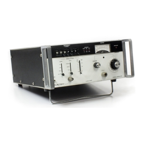
Front
panel
features
are
identified
by
number
in
Figure
3-1.
Each
numbered
feature
is
briefly
described
in
the
following
paragraph
with
the
same
number.
3-1
SEC'!'ION 3
OPERATING INSTRUCTIONS
1.
POWER
The
power
switch
turns
on/off
the
2500.
CAUTION
Allow
a
2-second
time
interval
between
turning
power
off
and
on.
The
fan
has
a
current
protection
circuit
that
turns
off
if
excess
current
is
drawn.
If
the
uni
t
is
turned
off
and
on
too
quickly
the
surge
current
could
cause
the
pro-
tection
circuit
to
disengage
power
to
the
fan,
resulting
in
possible
damage
to
the
instrument.
Features
numbered
2
through
13
are
function
controls
(keys)
and
are
grouped
together
into
a
keypad
for
operator
convenience.
Keys
numbered
2
through
7
are
associated
with
selecting
the
modulation
source,
if
any.
2.
INT
.AM
The
internal
.AM
key
selects
the
in-
ternal
amplitude
modulation
mode
of
operation
and
is
associated
with
key
4.
3.
EXT
.AM
The
external
.AM
key
selects
the
ex-
ternal
amplitude
modulation
mode.
An
external
source,
connected
at
the
MOD
IN
connector
(feature
24)
provides
the
amplitude
modulation
source.
4.
400/1000
The
40011000
key
determines
which
in-
ternal
source
rate,
400
or
1000
Hz,
Scans by Artekmedia => 2011
I
'WAVETEK
--llee
11Hz
SI
;na1
Guna+or
_od.1
26ee
lIodulatlon
21
~Id:::::===~~
lC::==:
=========:::!J~
~~
~
o
EJB
15 16
----------
---~----
-===-
IMm~P0·
~.
@
Id~m~
ION~~~
0012-0o~6163
Figure
3-1.
Wavetek
Model
2500
Front
Panel
3-2
Scans by ArtekMedia => 2011
ArtekMedia
Digitally signed by ArtekMedia
DN: cn=ArtekMedia, o=ArtekMedia.com, ou,
[email protected], c=US
Date: 2011.06.18 21:06:09 -05'00'
provides
the
internal
AM
modulation
selected
by
key
2,
above,
or
the
in-
ternal
FM
modulation
selected
by
key
5,
below.
5.
INT
FM
The
internal
FM
key
selects
the
in-
ternal
frequency
modulation
mode
of
operation
and
is
associated
with
key
4,
above.
6.
EXT
FM
The
external
FM
key
selects
the
ex-
ternal
FM
modulation
mode.
An
external
source,
connected
at
the
MOD
IN
con-
nector
(feature
24)
provides
the
fre-
quency
modulation
source.
7.
MOD
OFF
The
modulation
off
key
turns
off
all
modulation
of
the
carrier
wave,
selec-
ting
an
unmodulated
CW
RF
output.
8.
STR
The
store
key
initiates
the
procedure
to
store
front
panel
settings
in
non-
volatile
RAM
(Random
Access
Memory).
There
are
15
locations
available
for
stored
settings.
(See
feature
13).
9.
RCL
The
recall
key
initiates
the
procedure
to
recall
front
panel
settings
from
storage
locations
in
non-volatile
RAM.
10.
LCL
If
the
unit
is
in
the
remote
control
mode
of
operation
(GPIB),
the
local
key
may
be
used
to
reestablish
front
panel
control
of
the
2500
from
the
remote
control
source.
(Please
note
that
GPIB
documentation
is
provided
in
Section
6
of
this
manual.)
When
the
unit
is
in
the
Local
Mode
of
operation,
the
LCL
switch
turns on/off
the
display
backlighting.
3-3
11.
FREQ
The
frequency
key
initiates
cedure
to
establish
the
carrier
frequency.
12.
LVL
the
pro-
RF
output
The
level
key
initiates
the
procedure
to
establish
the
RF
output
power
level.
13.
INIT
When
the
unit
is
in
the
Local
Mode
of
operation,
the
initialize
key
sets
the
front
panel
controls
to
the
values
stored
as
stored
setting
#15
(see
feature
8,
above).
When
the
unit
is
in
the
remote
mode
(GPIB),
the
INIT
key
provides
an
SRQ
message
to
the
GPIB
bus.
(See
Section
6
of
this
manual
for
greater
detail.)
14.
NUMERIC
ENTRY
KEYPAD
Numeric
data
is
entered
using
the
keys
grouped
together
in
this
12
key
keypad.
The
digits
(0-9)
and
a
decimal
point
(
.)
are
represented
by
individual
keys.
The
+/-
key
is
used
to
establish
the
sign
of
an
entry
(positive
or
negative)
.
Features
15
and
16
work
together
to
allow
the
operator
fine
and
coarse
con-
trol
of
output
frequency,
output
level,
AM
depth
(%),
and
FM
deviation
(kHz).
Use
of
features
15
and
16
are
described
in
detail
later
in
this
chapter.
15.
SPIN
KNOB
Rotating
the
spin
knob
in
a
clockwise
direction
will
increase
the
values
listed
immediately
above.
Counter-
clockwise
rotation
will
decrease
those
values.
16.
.....-+
The
left
and
the
spin
knob
and
establish
right
arrow
keys
below
function
as
cursor
keys
the
digit
in
a
function
Scans by Artekmedia => 2011
display
(see
items
21
througb
23)
con-
trolled
by
the
spin
knob.
This
"reso-
lution"
digit
and
the
digits
to
its
left
are
controlled
by
the
spin
knob.
The
resolution
digit
is
underlined
on
the
display.
Digits
to
the
right
of
the
resolution
digit
will
not
change
as
the
spin
knob
is
rotated.
Features
17
through
19
serve
to
ter-
minate
RF
frequency,
level,
and
modu-
lation
settings.
17.
MHz/mV
The
MHz/mV
key
frequency
(MHz)
entry.
18.
kHz/lJV
terminates
or
output
an
output
level
(mV)
The
kHz/lJV
key
terminates
output
frequency
and
FM
deviation
(kHz)
and
output
level
(lJV)
entries.
19.
'o/dBm
The
%/dBm
key
terminates
AM
modulation
depth
(c;;.)
and
output
level
(dBm)
entries.
20.
RF
ON/OFF
The
RF
on/off
key
is
used
to
switch
the
RF
signal
on
and
off
at
the
RF
out
connector
(feature
25).
Features
21
through
23
are
the
displays
that
indicate
operational
status
of
the
instrument
and
provide
information
about
the
RF
output
characteristics.
21.
MODULATION
DISPLAY
The
modulation
display
indicates
the
modulation
status
of
the
output
RF
signal.
The
output
signal
may
be
un-
modulated,
CW,
indicated
by
the
display
annunciator
"OFF".
The
signal
may
be
amplitude
(AM)
or
frequency
(FH)
modu-
lated,
using
an
internal
or
external
modulating
source.
The
display
annun-
ciators
are
"INT
AM", "EXT
AM,
"INT
FM",
and
"EXT
FM"
for
each
AM
or
FM
3-4
output.
Complex
modulation
(a
combina-
tion
of
A¥,
and
FM)
may
be
used.
AM
is
shown
on
the
display
as
%
modulation,
FM
as
kHz
deviation.
The
operator
may
select
an
internal
modulation
rate
of
400
or
1000
Hz,
with
the
selected
source
shown
on
the
display.
The
numeric
value
for
the
AM
or
FM
used
is
shown
on
the
display.
The
digit
con-
trolled
by
the
spin
knob,
the
resolu-
tion
digit
(see
features
15
and
16,
above)
is
underlined
on
the
display.
Finally,
the
modulation
display
will
show
the
characters
REM
when
the
unit
is
under
remote
control.
22.
FREQUENCY
DISPLAY
The
frequency
display
indicates
the
frequency
of
the
RF
carrier
output
in
MHz.
The
numeric
indicators
include
an
underlined
resolution
digit
used
with
spin
knob
control
of
the
frequency
(see
features
15
and
16,
above).
This
display
contains
annunciators
that
indicate
an
unlocked
phase
locked
loop
(UNLOCKED),
front
panel
settings
are
being
stored
(STORED),
front
panel
settings
are
being
recalled
(RECALLED),
and
the
instrument
is
performing
an
automatic
frequency
calibration
(CAL).
During
automatic
calibration
the
oscillator
being
calibrated
(numbered
1-4)
and
the
various
calibration
points
(1-51,
depending
on
the
oscillator)
are
indicated
as
calibration
proceeds.
23.
LEVEL DISPLAY
The
level
display
indicates
the
level
of
the
output
RF
signal
in
dBm, mV,
or
lJV.
The
numeric
indicators
include
an
underlined
resolution
digit
used
with
spin
knob
control
of
the
output
level
(see
features
15
and
16).
This
display
also
contains
annunciators
that
indicate
when
the
RF
circuit
breaker
is
tripped
(TRIPPED),
when
the
leveler
circuits
are
not
functioning
(UNI.VD),
and
whether
the
RF
output
is
on
or
off
(RF
ON/RF
OFF).
Features
24
and
25
are
input
and
output
connectors,
respectively.
Scans by ArtekMedia => 2011

Other Wavetek Portable Generator manuals

Wavetek 3000 User manual

Wavetek

Wavetek 3000 User manual

Wavetek 150 User manual

Wavetek

Wavetek 150 User manual

Wavetek 188 User manual

Wavetek

Wavetek 188 User manual

Wavetek 144 User manual

Wavetek

Wavetek 144 User manual

Wavetek FG3B User manual

Wavetek

Wavetek FG3B User manual

Wavetek 1370 Installation instructions

Wavetek

Wavetek 1370 Installation instructions

Wavetek 148A User manual

Wavetek

Wavetek 148A User manual

Wavetek 182A User manual

Wavetek

Wavetek 182A User manual

Wavetek 3510 User manual

Wavetek

Wavetek 3510 User manual

Wavetek 188 User manual

Wavetek

Wavetek 188 User manual

Wavetek 132 User manual

Wavetek

Wavetek 132 User manual

Wavetek 1001A User manual

Wavetek

Wavetek 1001A User manual

Wavetek 132 User manual

Wavetek

Wavetek 132 User manual

Wavetek 180 User manual

Wavetek

Wavetek 180 User manual

Wavetek 182A User manual

Wavetek

Wavetek 182A User manual

Wavetek 1001A User manual

Wavetek

Wavetek 1001A User manual

Wavetek 182A User manual

Wavetek

Wavetek 182A User manual

Popular Portable Generator manuals by other brands

Anritsu Rubidium MG36271A Operation manual

Anritsu

Anritsu Rubidium MG36271A Operation manual

Toyama TDG2500XP owner's manual

Toyama

Toyama TDG2500XP owner's manual

Agilent Technologies 33120A Service guide

Agilent Technologies

Agilent Technologies 33120A Service guide

LNI NitroGen Series operating manual

LNI

LNI NitroGen Series operating manual

Tektronix AWG7101 instructions

Tektronix

Tektronix AWG7101 instructions

Energizer EZG6000 user guide

Energizer

Energizer EZG6000 user guide

Baja BAi911LP Operator's manual

Baja

Baja BAi911LP Operator's manual

DUROMAX XP12000X user manual

DUROMAX

DUROMAX XP12000X user manual

Wacker Neuson GP 2500A user manual

Wacker Neuson

Wacker Neuson GP 2500A user manual

Parker DB Series owner's manual

Parker

Parker DB Series owner's manual

Northern Lights PX-300K2 Series A.C. Generators Operator's & parts manual

Northern Lights

Northern Lights PX-300K2 Series A.C. Generators Operator's & parts manual

ulsonix AIRCLEAN 40G user manual

ulsonix

ulsonix AIRCLEAN 40G user manual

Daewoo DAIG Series user manual

Daewoo

Daewoo DAIG Series user manual

Arvey A1 User manual and warranty statement

Arvey

Arvey A1 User manual and warranty statement

HERON 8896431 Translation of the original user manual

HERON

HERON 8896431 Translation of the original user manual

Klein Tools KTB1000 instruction manual

Klein Tools

Klein Tools KTB1000 instruction manual

Bohmer-AG W Series Operation manual

Bohmer-AG

Bohmer-AG W Series Operation manual

Brightwin Electronics BRT LB02G quick start guide

Brightwin Electronics

Brightwin Electronics BRT LB02G quick start guide

manuals.online logo
manuals.online logoBrands
  • About & Mission
  • Contact us
  • Privacy Policy
  • Terms and Conditions

Copyright 2025 Manuals.Online. All Rights Reserved.