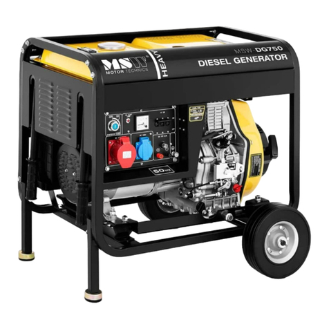
Endress ESE 604 DBG DIN User manual


This manual suits for next models
4
Table of contents
Other Endress Portable Generator manuals
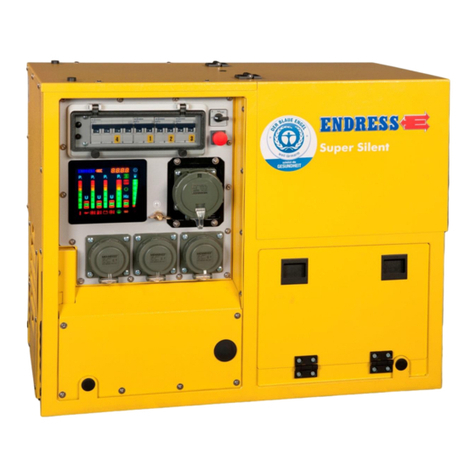
Endress
Endress ESE 608 DHG ES DI DUPLEX User manual
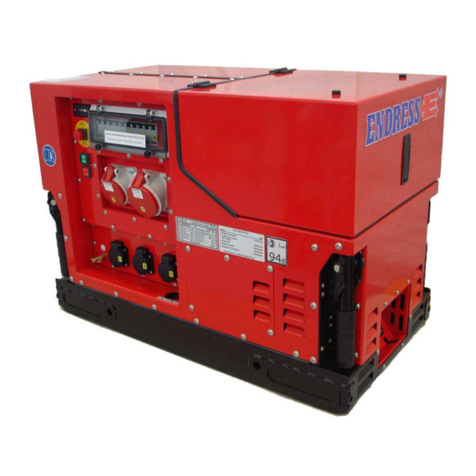
Endress
Endress ESE 808 DBG ES DUPLEX SILENT User manual
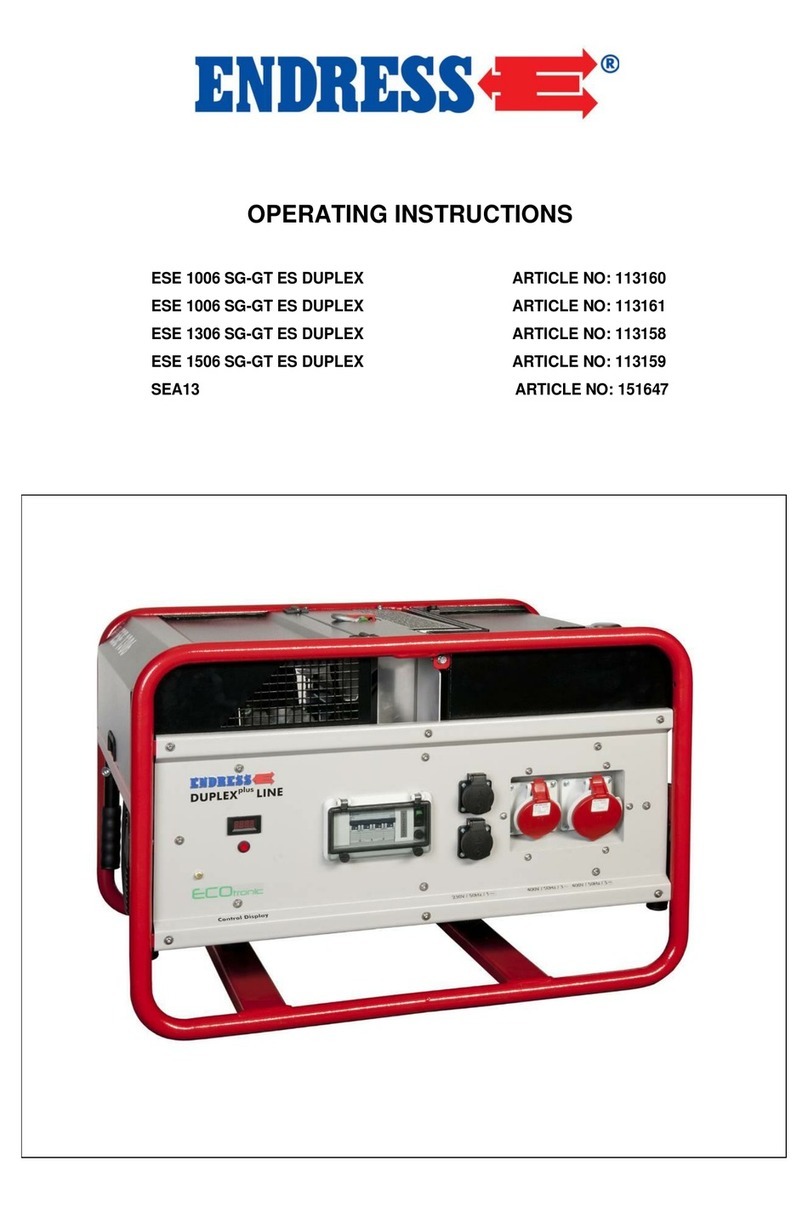
Endress
Endress ESE 1006 SG-GT ES DUPLEX User manual
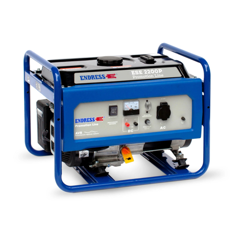
Endress
Endress ESE 2200 P User manual
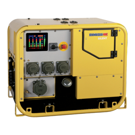
Endress
Endress ESE 607 DBG ES DIN User manual
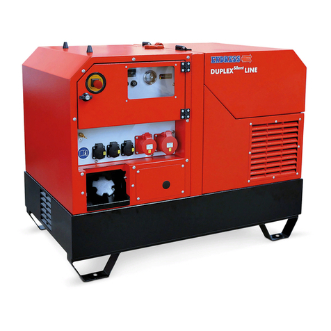
Endress
Endress ESE Series Operational manual
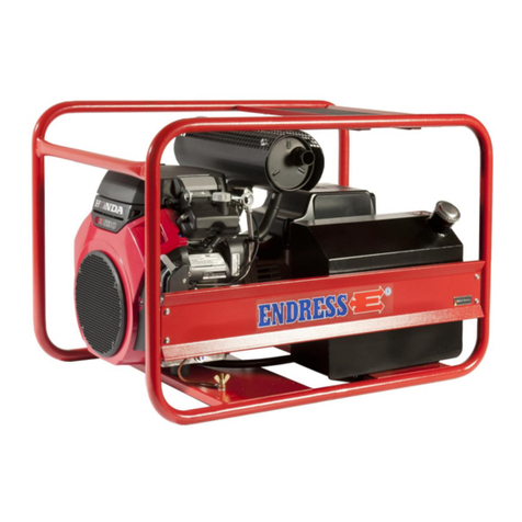
Endress
Endress ESE 1306 HS-GT ES User manual
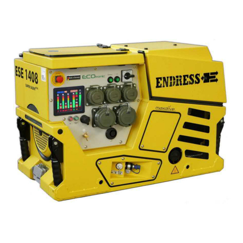
Endress
Endress ESE 1408 Operational manual
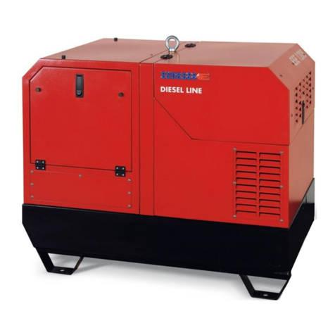
Endress
Endress ESE 1008 LG ES DIESEL DUPLEX SILENT User manual

Endress
Endress ESE Series Operating instructions
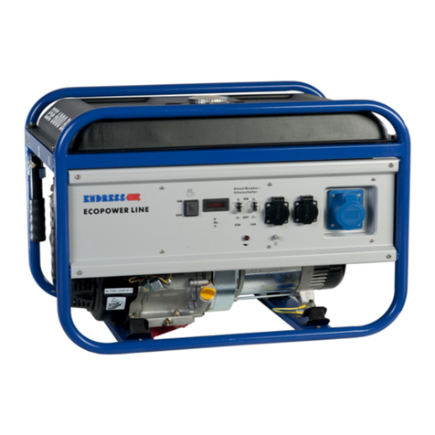
Endress
Endress ECO Power Line ESE 3000 BS Operational manual

Endress
Endress ESE 67 IW Operational manual

Endress
Endress ESE Operational manual

Endress
Endress ESE 206 HS-GT User manual

Endress
Endress ESE 2300 i Operational manual

Endress
Endress EZG 24/2 User manual
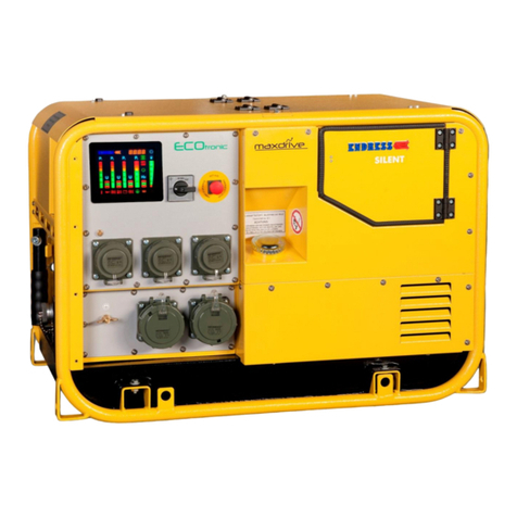
Endress
Endress ESE 807 DBG DIN User manual
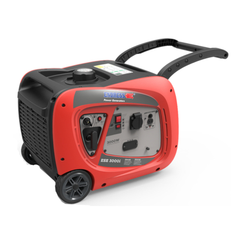
Endress
Endress ESE 3000 i Operating instructions
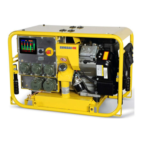
Endress
Endress ESE 1304 DBG ES DIN User manual
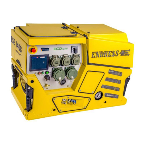
Endress
Endress ESE 1408 DGB ES DIN User manual
Popular Portable Generator manuals by other brands
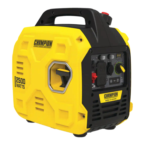
Champion Global Power Equipment
Champion Global Power Equipment 201046 quick start guide
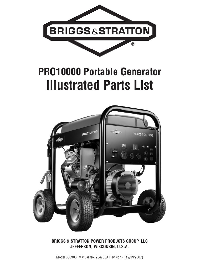
Briggs & Stratton
Briggs & Stratton PRO10000 030383 Illustrated parts list
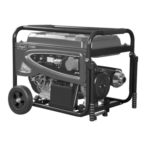
Scheppach
Scheppach SG7100 Translation of original instruction manual
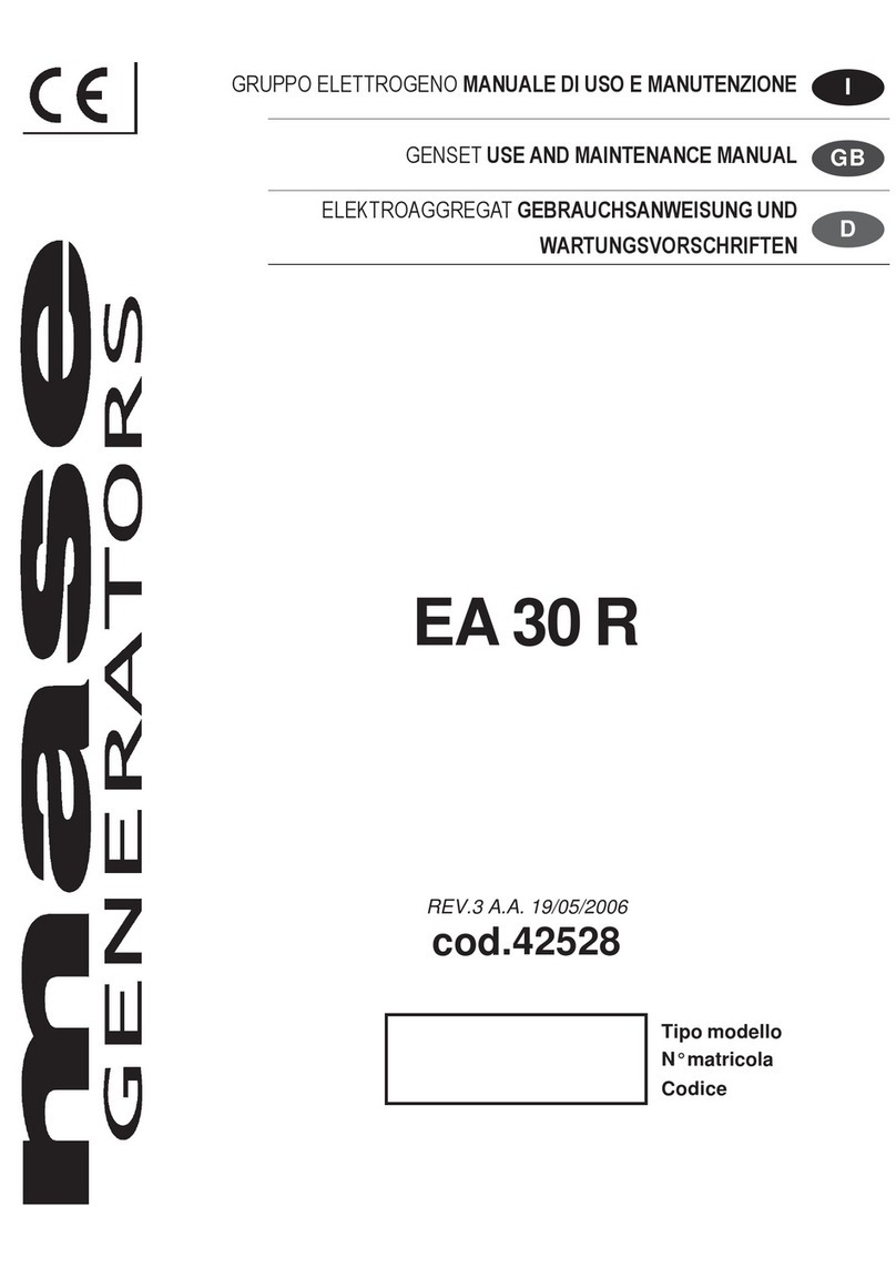
Mase Generators
Mase Generators EA 30 R Use and maintenance manual

iWeld
iWeld QuickSilver MIG 240 user manual
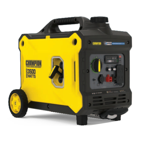
Champion
Champion 100571 quick start guide
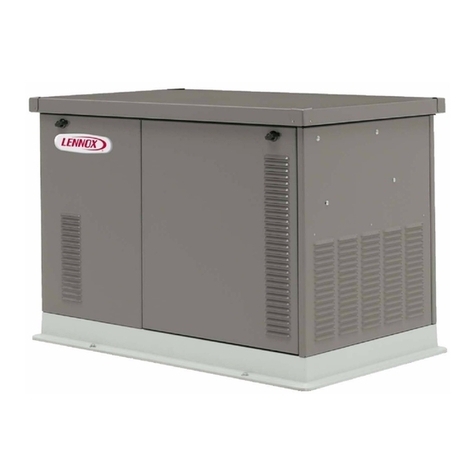
Lennox
Lennox RGEN12 Operation manual
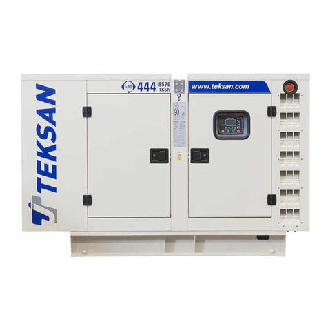
TEKSAN
TEKSAN DIESEL GENERATOR SETS Operation and maintenance manual
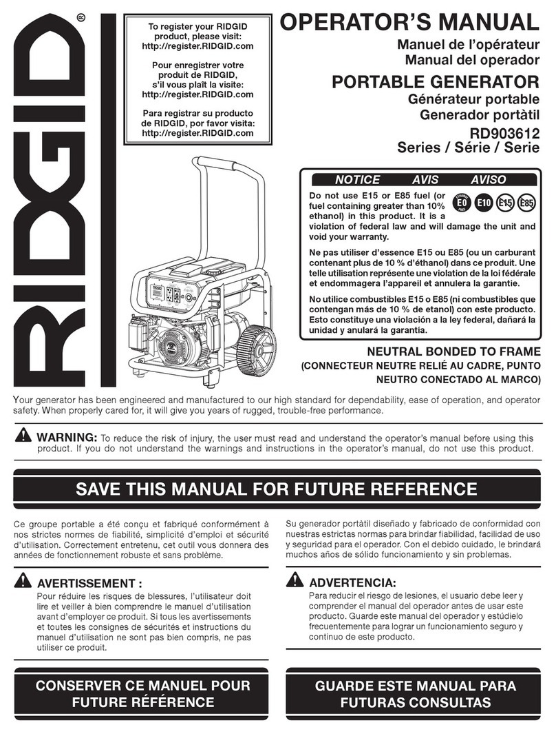
RIDGID
RIDGID RD903612 Series Operator's manual

Buffalo
Buffalo Sportsman GEN10K instruction manual

GenConnex
GenConnex GXK LPNG-EU7000is-Kit-EC5.0 owner's manual

MARELD
MARELD POWER STATION 1000W instruction manual

