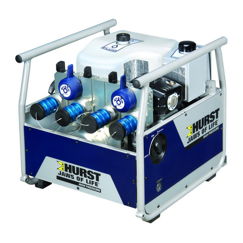
HURST P 650 User manual

1/20
Classification: Reference: Date:
BR12-003a NTB12-086a October 25,2012
2011-2012 LEAF; BRAKE PEDAL SENSITIVE AT SPEEDS
BELOW 15 MPH
APPLIED VEHICLES: 2011-2012 LEAF(ZE0)
APPLIED VIN AND DATE : Built before JN1AZ0CP(*)CT 023494 // June 6, 2012
IF YOU CONFIRM
•Customer may experience some brake sensitivity at speeds below 15 mph. The
customer may experience this issue while in stop-and-go traffic conditions.
And
•No DTCs are present in the Electrically-driven Intelligent Brake Control Unit.
¾If DTCs are present, refer to the specific section of the applicable Electronic
Service Manual (ESM) and diagnose first.
ACTION
1. Refer to step 14 in the SERVICE PROCEDURE to confirm this bulletin applies to the
vehicle you are working on.
2. If this bulletin applies, reprogram the Electrically-driven Intelligent Brake Control Unit
with CONSULT III plus (CIII plus).
IMPORTANT: The purpose of ACTION (above) is to give you a quick idea of the work you
will be performing. You MUST closely follow the entire SERVICE PROCEDURE as it
contains information that is essential to successfully completing this repair.
Nissan Bulletins are intended for use by qualified technicians, not 'do-it-yourselfers'. Qualified technicians are
properly trained individuals who have the equipment, tools, safety instruction, and know-how to do a job
properly and safely. NOTE: If you believe that a described condition may apply to a particular vehicle, DO
NOT assume that it does. See your Nissan dealer to determine if this applies to your vehicle.
This bulletin has been amended. The Title, Applied Vehicles, Applied VIN and Date, and If You
Confirm sections have been revised. Please discard all previous versions.

CLAIMS INFORMATION
Submit a Primary Part (PFP) line claim using the following claims coding:
DESCRIPTION PFP OP CODE SYM DIA FRT
Reprogram E-Act (1) PX65AA ZE 32 0.5
(1) Refer to the electronic parts catalog (FAST) and use the appropriate ABS actuator
assembly part number (46007-*****) as the Primary Part (PFP).
SERVICE PROCEDURE
Reprogram Electrically-driven Intelligent Brake Control Unit
1. Before continuing, it is IMPORTANT to make sure:
•ASIST on the CONSULT PC has been freshly synchronized (updated).
•All CONSULT related software updates (if any) have been installed.
NOTE: The CONSULT PC automatically gets all reprogramming software during
ASIST synchronization.
CAUTION:
•Turn off all cell phones and external Bluetooth devices within range of C-III plus.
•Do not touch C-III plus during reprogramming.
•Do not disconnect the AC adaptor during reprogramming.
•Do not disconnect the “plus” VI’s diagnostic cables during reprogramming.
•Do not touch the power (“ignition”) switch during reprogramming.
•Do not touch any electrical switch during reprogramming.
2. Have the GR8 Multitasking Battery Diagnostic Station (battery tester/charger)
available and ready to use.
•For proper setup, go to Page 20, GR8 Multitasking Battery Diagnostic Station.
•Do not connect the battery tester/charger at this time. The battery tester/charger
will be set up later in this bulletin.
CAUTION: Do not charge the High Voltage (HV) Lithium Ion battery during
reprogramming.
NOTE:
¾Check to see if the timer for either charging or climate control is on. If on, turn
it off and make sure to turn it back on after reprogramming.
2/20 NTB12-086a

3. Once all ASIST and CONSULT related updates have been verified/performed, attach
the CONSULT PC to vehicle.
•Connect the plus VI to the vehicle.
•Connect the CONSULT PC to the plus VI with the USB cable.
•Connect the AC adapter to the CONSULT PC.
4. Turn on the CONSULT PC, and then open C-III plus.
5. Depress the vehicle’s power (“ignition”) switch twice without depressing the
brake pedal.
•The meter and gauges will illuminate.
CAUTION: Do Not set the vehicle in “READY to drive” mode.
NOTE: Make sure all accessories are turned off.
6. After the plus VI is recognized, select Reprogramming Configuration (Write).
NOTE: Make sure all applications other than C-III plus are closed.
Step
6
plus VI is
recognized
Figure 1
3/20 NTB12-086a

7. Select Next.
Figure 2
Step
7
8. Select LEAF and 2011/ 2012 or Automatic Selection (VIN).
•If Automatic Selection (VIN) is selected, wait for the Reading VIN screen to
complete (picture not shown).
9. Select Select.
This works,
too Step
8
Step
9
Figure 3
4/20 NTB12-086a

10.Verify the VIN in VIN or Chassis # matches that of the vehicle’s.
•If the correct VIN exists, select Confirm.
Verify
here
Figure 4
If OK, select
Confirm
11.On the next screen, select Confirm.
Step
11
Figure 5
5/20 NTB12-086a

12.Select BRAKE.
•Wait for system call to complete.
Step
12
Figure 6
13.Select Reprogramming.
Step
13
Figure 7
6/20 NTB12-086a

14.Write down the Part Number on the vehicle’s repair order (see Figure 8).
•If the BRAKE part number is 46007-3NA0A, continue with reprogramming.
¾Select Save, and then go to Step 15.
•If the BRAKE part number is not 46007-3NA0A, this bulletin does not apply or it has
already been done. Close C-III plus (select Home, and then the “X”) and the
CONSULT PC, disconnect from the vehicle.
If BRAKE P/N is
not 46007-3NA0A,
select Home, and
then
select
“
X
”
Verify
here
Figure 8
If OK, select
Save
15.Select Next.
Step
15
Figure 9
7/20 NTB12-086a

16. Read the precautions on page 1, and then select page 2 (page 2 not shown) with
arrow. After reading page 2, select Confirmed instructions, and then select Next.
Figure 10
Step
16
NOTE: In some cases, more than one new P/N for reprogramming is available.
¾In this case, the screen in Figure 11 will display.
¾Select and use the reprogramming option that does not have the message
“Caution! Use ONLY with NTBXX-XXX”.
•If you get this screen and it is blank (no reprogramming listed), it may mean that
there is no reprogramming available for this vehicle, this bulletin does not apply or it
has already been done.
Figure 11
8/20 NTB12-086a

17.Verify “Current” and “After Reprogramming” part numbers are listed, then select Next.
Figure 12
Verify P/Ns
above, then
select Next
18.If this screen appears, select Other Operation.
Step
18
Figure 13
9/20 NTB12-086a

19.Open the hood, and then set up the GR8 Multitasking Battery Diagnostic Station
(battery tester/charger) for the 12V battery.
•For battery charger/tester setup, refer to Page 20, GR8 Multitasking Battery
Diagnostic Station Setup.
CAUTION: Battery voltage must stay between 12 volts and 15.5 volts.
CAUTION: Do not charge the High Voltage (HV) Lithium Ion battery during
reprogramming.
Figure 14
20.Confirm that battery voltage is correct, and then select Next.
NOTE: Battery voltage must stay within specified range to make the indicator turn green.
DO NOT CHARGE
during reprogramming
12V battery
Monitor 12V
battery
volta
g
e here
Must be
“Green” before
selecting Next
Figure 15
10/20 NTB12-086a
Other manuals for P 650
1
Table of contents
Other HURST Portable Generator manuals


