Endress+Hauser TMD1000 TMD1 User manual

Products Solutions Services
Operating Instructions
TMD1000 TMD1
HHT2 Hand Held Terminal
SFT MODE OFF ON
HAND HELD TERMINAL
HHT-2-
7 8 9
0ENT
4 5 6
1 2 3
D E F
A B C
BA00429G/00/EN/03.19
71427112
2019-12-27

TMD1000 TMD1
2 Endress+Hauser
Order code:
Ext. ord. cd.:
Ser. no.:
www.endress.com/deviceviewer Endress+Hauser
Operations App
XXXXXXXXXXXX
XXXXX-XXXXXX
XXX.XXXX.XX
Serial number
1.
3.
2.
A0023555

TMD1000 TMD1 Table of contents
Endress+Hauser 3
Table of contents
1 About this document ................ 4
1.1 Document function ..................... 4
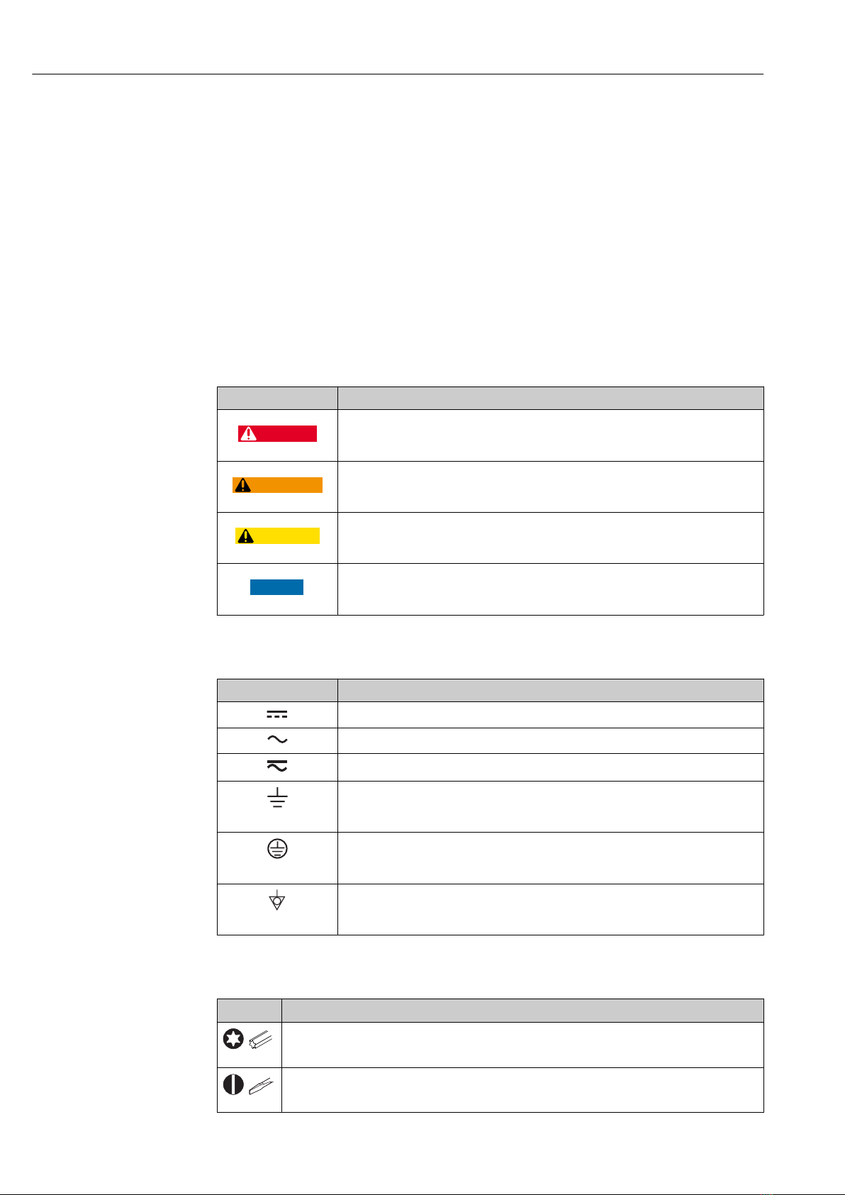
1.2 Symbol .............................. 4
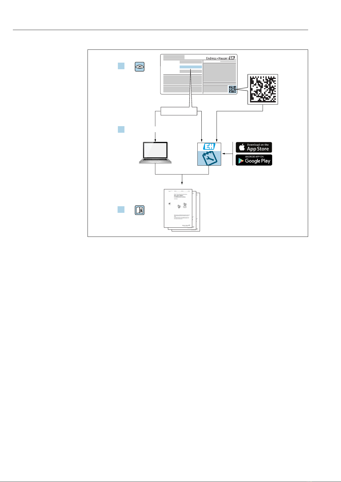
1.3 Documentation ........................ 7
1.4 Registered trademarks ................... 7
2 Basic safety instructions ............ 8
2.1 Requirements for personnel ............... 8
2.2 Designated use ........................ 8
2.3 Workplace safety ....................... 8
2.4 Operational safety ...................... 9
2.5 Product safety ......................... 9
3 Product description ................ 10
3.1 Product design ........................ 10
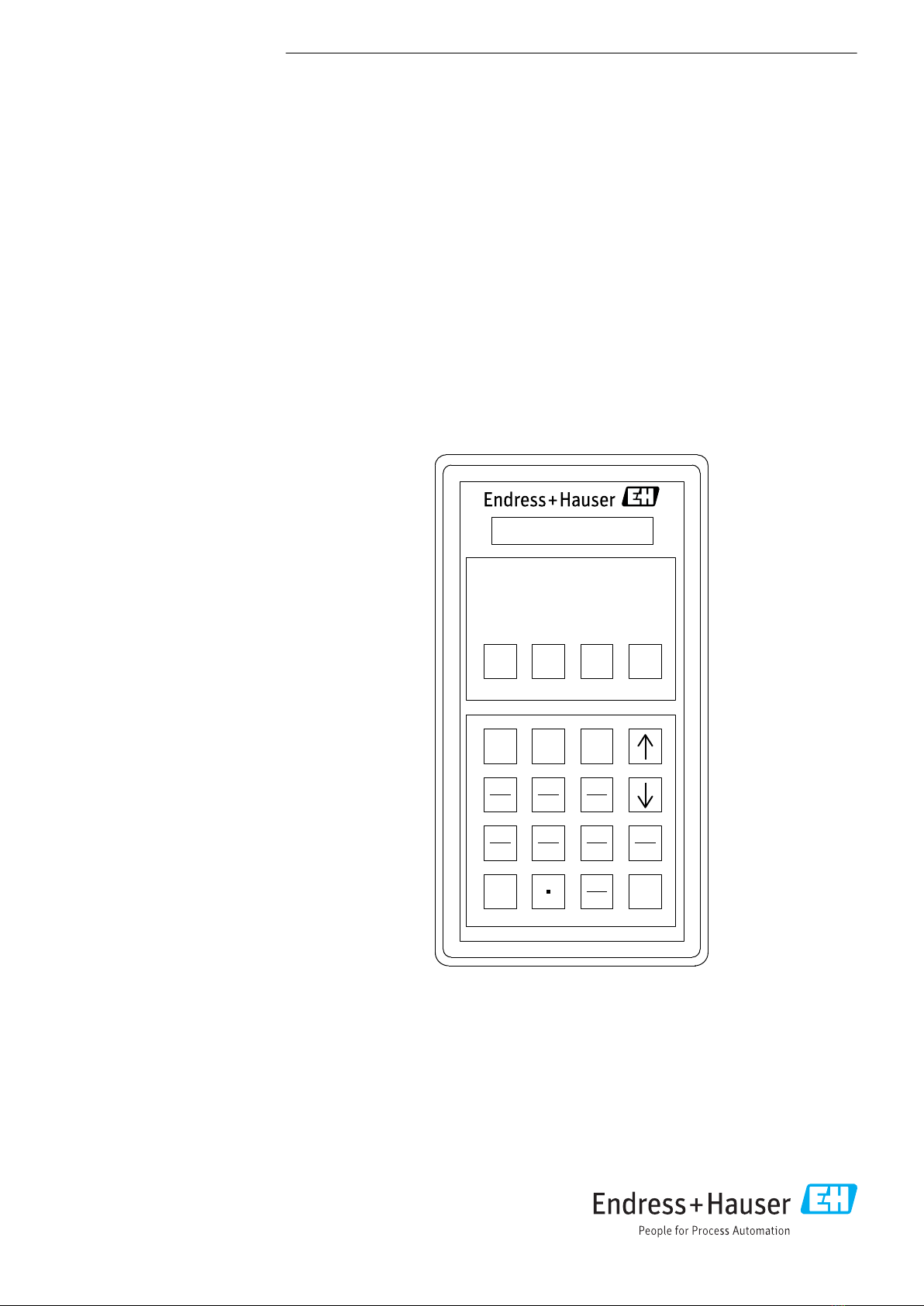
3.2 Keypad ............................. 10
3.3 Technical data ........................ 11
4 Incoming acceptance and product
identification ..................... 12
4.1 Incoming acceptance ................... 12
4.2 Product identification .................. 12
4.3 Manufacturer contact address ............ 13
4.4 Storage and transport .................. 13
5 Electrical connection .............. 15
5.1 Wiring ............................. 15
6 Operation ......................... 16
6.1 Pre-operation and settings ............... 16
6.2 Power ON ........................... 16
6.3 Device selection ....................... 17
6.4 MODE00 function display and setting
change ............................. 17
6.5 MODE01 Operation and display setting ..... 21
6.6 MODE02 level and status ................ 22
6.7 MODE03 data setting operation for level .... 22
6.8 MODE05 parallel output ................ 23
6.9 MODE06 contact output (Alarm) .......... 23
6.10 MODE07 spot temperature device 1 point
input ............................... 24
6.11 MODE08 spot temperature device 3 point
input ............................... 25
6.12 MODE09 multi-element average temperature
device input .......................... 25
6.13 MODE10 single-element average
temperature ......................... 26
6.14 MODE11 Analog 4 to 20 mA output (No. 1) .. 27
6.15 Analog 4 to 20 mA output No. 2 .......... 28
6.16 MODE13 2-way, 2-wire transmission
output .............................. 29
6.17 MODE14 Analog 4 to 20 mAinput ......... 29
6.18 MODE15 FFi transmission output .......... 30
6.19 MODE21 MIF-4 data setting ............. 30
6.20 MODE30 NMT: V0 (temperature value)
setting .............................. 31
6.21 MODE31 NMT: V1 (Element temperature)
setting .............................. 31
6.22 MODE32 NMT: V2 (Element temperature)
setting .............................. 31
6.23 MODE33 NMT: V3 (element position)
setting .............................. 32
6.24 MODE34 NMT: V4 (element position)
setting .............................. 32
6.25 MODE35 NMT: V5 (water scale temperature)
setting .............................. 33
6.26 MODE36 NMT: V6 (water scale and power
supply) adjustment .................... 34
6.27 MODE37 NMT: V7 (Temperature
adjustment) setting .................... 34
6.28 MODE38 NMT: V8 (Device) setting ........ 36
6.29 MODE39 NMT: V9 (Device) setting ........ 37
7 Diagnostics and troubleshooting ... 38
7.1 General troubleshooting ................. 38
7.2 Maintenance and update ................ 38
7.3 Battery replacement ................... 38
7.4 Firmware history ...................... 40
8 Repair ............................ 41
8.1 General information on repairs ............ 41
8.2 Spare parts .......................... 41
8.3 Endress+Hauser services ................ 41
8.4 Return .............................. 42
8.5 Disposal ............................ 42
Index .................................. 43

About this document TMD1000 TMD1
4 Endress+Hauser
1 About this document
1.1 Document function
These Operating Instructions contain all the information that is required during various
phases of the life cycle of the device: from product identification, incoming acceptance and
storage, to mounting, connection, operation and commissioning through to
troubleshooting, maintenance and disposal.
1.2 Symbol
1.2.1 Safety symbols
Symbol Meaning
DANGER
DANGER!
This symbol alerts you to a dangerous situation. Failure to avoid this situation will
result in serious or fatal injury, as well as a risk of fire or explosion.
WARNING
WARNING!
This symbol alerts you to a dangerous situation. Failure to avoid this situation will
result in a risk of serious or fatal injury, fire or explosion.
CAUTION
Note
This symbol alerts you to a dangerous situation. Failure to avoid this situation will
result in a risk of minor or moderate injury and damages to properties.
NOTICE
NOTE!
This symbol contains information on procedures and other facts that do not result in
personal injury.
1.2.2 Electrical symbols
Symbol Meaning
Direct current
Alternating current
Direct current and alternating current
Ground connection
A grounded terminal that, as far as the operator is concerned, is grounded via a
grounding system.
Protective ground connection
A terminal that must be connected to the ground prior to establishing any other
connections.
Equipotential connection
This connects with the grounding system at the plant.It includes equipotential line and
single point ground systems, depending on the norms of each country or company.
1.2.3 Tool symbols
Symbol Meaning
A0013442
Torx screwdriver
A0011220
Flat blade screwdriver

TMD1000 TMD1 About this document
Endress+Hauser 5
Symbol Meaning
A0011219
Phillips screwdriver
A0011221
Allen key
A0011222
Open-ended wrench
1.2.4 Symbols for certain types of information
Symbol Meaning
Permitted
Procedures, processes or actions that are permitted
Preferred
Procedures, processes or actions that are preferred
Forbidden
Procedures, processes or actions that are forbidden
Tip
Indicates additional information
Reference to documentation
A
Reference to page
Reference to graphic
Notice or individual step to be observed
1.
,
2.
,
3.
… Series of steps
Result of an operation or commissioning
Help in the event of a problem
Visual inspection
Operation via the local display
Operation via operating tool
Write-protected parameter
1.2.5 Symbols in graphics
Symbol Meaning
1, 2, 3 ... Item numbers
1.
,
2.
,
3.
… Series of steps
A, B, C, ... Graphics
A-A, B-B, C-C, ... Cross-sections

About this document TMD1000 TMD1
6 Endress+Hauser
Symbol Meaning
-
Hazardous area
Indicates the hazardous area
.
Safe area (non-hazardous area)
Indicates the non-hazardous area
1.2.6 Device symbol
Symbol Meaning
Safety instructions
Observe the safety instructions contained in the associated Operating Instructions.
Temperature resistance of the connection cables
Specifies the minimum value of the temperature resistance of the connection cables.

TMD1000 TMD1 About this document
Endress+Hauser 7
1.3 Documentation
For an overview of the scope of the relevant Technical Documentation included with
the product, refer to the following:
• The W@M Device Viewer: Enter the serial number from the nameplate
(www.endress.com/deviceviewer).
• The Endress+Hauser Operations App: Enter the serial number from the nameplate.
1.3.1 Technical Information
The Technical Information contains all the technical data on the device and provides an
overview of the accessories and other products that can be ordered for the device.
Device Technical Information
Digital Transmitter TMD1000 TMD1 TI00463G
1.3.2 Operating Instructions (BA)
The Operating Instructions contain all the information that is required during various
phases of the life cycle of the device: from product identification, incoming acceptance and
storage, to mounting, connection, operation and commissioning through to
troubleshooting, maintenance and disposal.
The Operating Instructions also contain detailed descriptions of each parameter in the
operation menu. The description is aimed at those who work with the device over the
entire life cycle and perform specific configurations.
Device Operating Instructions
Digital Transmitter TMD1000 TMD1 BA00427G
BA00428G
BA00429G
1.3.3 Safety Instructions (XA)
Feature 030 "Approval" Meaning XA
4 TIIS Exd IIB T4 XA01072G
5 FM XP Cl.I Div.1 Gr.C-D, AEx d IIB T4 XA01089G
1.4 Registered trademarks
HART®
Registered trademark of the HART Communication Foundation, Austin, USA

Basic safety instructions TMD1000 TMD1
8 Endress+Hauser
2 Basic safety instructions
2.1 Requirements for personnel
The personnel for installation, commissioning, diagnostics and maintenance must fulfill
the following requirements:
‣Be specialists who are trained and have a relevant qualification for this specific
function and task.
‣Be authorized by the plant owner-operator.
‣Be familiar with local/national regulations.
‣Before starting work, read and understand the instructions in the Operating
Instructions and supplementary documentation as well as the certificates (depending
on the application).
‣Follow instructions and comply with basic conditions.
The operating personnel must fulfill the following requirements:
‣Be instructed and authorized according to the requirements of the task by the facility's
owner-operator.
‣Follow the instructions in this manual.
2.2 Designated use
Application and measured materials
Depending on the version ordered, the device can also be used with potentially explosive,
flammable, poisonous or oxidizing materials.
Devices that are used in hazardous areas have corresponding labels on their nameplates.
To ensure that the device remains in proper condition for the operation time:
‣Only use the device in full compliance with the data on the nameplate and the general
conditions listed in the Operating Instructions and supplementary documentation.
‣Check the nameplate to verify if the device can be put to its intended use in hazardous
areas.
‣If the device is not operated at an atmospheric temperature, compliance with the
relevant basic conditions specified in the relevant device documentation is absolutely
essential.
‣Protect the device permanently against corrosion from environmental influences.
‣Observe the limit values in the "Technical Information".
The manufacturer is not liable for damage caused by improper or non-designated use.
2.3 Workplace safety
For work on and with the device:
‣Wear the required personal protective equipment according to local/national
regulations.

TMD1000 TMD1 Basic safety instructions
Endress+Hauser 9
2.4 Operational safety
Risk of injury!
‣Operate the device in proper technical conditions and fail-safe conditions only.
‣The plant owner-operator is responsible for interference-free operation of the device.
Modifications to the device
Unauthorized modifications to the device are not permitted and can lead to unforeseeable
dangers:
‣If modifications are nevertheless required, contact your Endress+Hauser Sales Center.
Repair
To ensure continued operational safety and reliability:
‣Carry out repairs on the device only if they are expressly permitted.
‣Observe local/national regulations pertaining to repair of an electrical device.
‣Use only original spare parts and accessories from Endress+Hauser.
Ex-area
Observe the following notes to eliminate the risk of danger to persons or the facility when
the device is used in Ex-areas (e.g. explosion protection, pressure equipment safety):
‣Check the model nameplate to ensure that the ordered device is explosion proof.
‣Observe the specifications in the separate supplementary documentation attached to
these Instructions.
2.5 Product safety
This device was designed in accordance with GEP (Good Engineering Practice) to meet
state-of-the-art safety requirements, has been tested and left the factory in a condition in
which it is safe to operate. It meets the general safety standards and legal requirements.

Product description TMD1000 TMD1
10 Endress+Hauser
3 Product description
3.1 Product design
All operations on HHT2 are done by using twenty keys on the key pad. The upper four keys
are used to turn on/off the power and select modes. Lower sixteen keys are used to select
items and input values.
Refer to "Basic Operations and Setting" and "Option Input and Output Setting" for
details.
SFT MODE OFF ON
HAND HELD TERMINAL
HHT-2-
7 8 9
0ENT
4 5 6
1 2 3
D E F
A B C
A0038049
1 HHT2 Display
3.2 Keypad
Name Descriptions
ON Power ON switch: Keep pressing until the display appears on the LCD screen.
OFF Power OFF switch: Keep pressing until the display appears on the LCD screen. The power will turn
off approximately 4 minutes after the completion of key operation due to the auto-power off
function.
MODE Mode display switch: MODE No.input standby screen will appear.↑ and ↓ keys are usedto change
the MODE No.
SFT Shift key: Press an alphabet key or the ESC key while holding down the shift key when entering
alphabets A through F and ESC.

TMD1000 TMD1 Product description
Endress+Hauser 11
Name Descriptions
↑ Device selection screen: The name of the previous device will appear. MODE, ITEM selection
screen: The MODE or ITEM screen that is one step smaller than the MODE or ITEM that is being
displayed will appear.
↓ Device selection screen: The name of the next device will appear. The MODE or ITEM screen that
is one step larger than the MODE or ITEM that is being displayed will appear.
ESC/BS ESC: Pressing ESC and SFT key simultaneously will return the screen to the Device Selection
screen when the mode and item that is currently being displayed have been entered. BS:
Backspace key, which deletes one character from the input characters
ENT Setting mode key (Input key)
3.3 Technical data
Category Items Descriptions
Displays Display element Liquid Crystal Display (LCD)
Display character 16 characters x 2 digits
Dot configuration 5 x 7 dot + cursor
Display font size 2.95 (width) x 5.55 (height)
Key board Key top Vinyl sheet splash resistant
Switch Membrane switch
Interface Basic format Optical data link
Transmission form A type: 2-way, 2-wire
Transmission rate 1953.2bps
Power supply Battery AA alkaline battery (LR6 1.5 V) x 4 batteries
Consumption current 45 mA (Typ)
Uptime (continuous use) Approximately 25 hours (LR6(LR6 x 4 batteries /
ambient temperature 25 °C (77 °F))
Automatic power off Approximately 4 minutes after the last input recognition
Low battery alarm Approximately 5 V alarm is displayed when there is no
communication
Appearance External Dimensions 191 mm (7.52 in) x 102 mm (4.01 in) x 29 mm (1.14 in)
Material Plastic (ABS resin)
Weight Approximately 430 g (0.95 lb)
Structure Intrinsically safe construction i2G3
Temperature Ambient temperature –10 to 40 °C (14 to 104 °F) (however, there should be no
condensation)
Accessory Soft case Vinyl leather x 1 case
Battery LR6 x 4 batteries
Communication cable Optic fiber with optic cable (1 m (3.28 ft)) x 1 cable

Incoming acceptance and product identification TMD1000 TMD1
12 Endress+Hauser
4 Incoming acceptance and product
identification
4.1 Incoming acceptance
Upon receipt of the goods check the following:
• Are the order codes on the delivery note and the product sticker identical?
• Are the goods undamaged?
• Do the nameplate data match the ordering information on the delivery note?
• If required (see nameplate): Are the Safety Instructions (XA) enclosed?
If any one of these conditions is not met, contact your Endress+Hauser Sales Center.
4.2 Product identification
The following options are available for the identification of the measuring device:
• Nameplate
• Extended order code with breakdown of the device features on the delivery note
• Enter serial numbers from nameplates in the W@M Device Viewer
(www.endress.com/deviceviewer); all information about the device is displayed.
• Enter the serial number from the nameplates into the Endress+Hauser Operations App
or scan the 2-D matrix code (QR code) on the nameplate with the Endress+Hauser
Operations App; all the information for the measuring device is displayed.
For an overview of the scope of the enclosed associated Technical Documentation, refer to
the following:
• The W@M Device Viewer: Enter the serial number from the nameplate
(www.endress.com/deviceviewer).
• The Endress+Hauser Operations App: Enter the serial number from the nameplate or
scan the 2-D matrix code (QR code) on the nameplate.

TMD1000 TMD1 Incoming acceptance and product identification
Endress+Hauser 13
4.2.1 Nameplate
cdeテスター/Handy terminal
Order code
^_`a / HHT-2Ex Proof model :
/ i2G3^_bC Protection class :
"# :/ Rating
%& / Power supply : DC 6 V 29 mA
( R6P, LR6マンガン+%, アルカリマンガン+%,
3×4 )0 1234
(maganese dry battery R6P or alkali-manganese dry
battery LR6×4 series connection)
567889:び<=の?@ABCをEなわないでください。
Don’t modify parts and circuits of this instrument.
%,のNOはQRSTUでEなってください。
Don’t change batteries at hazardouse area.
XYZ[ ℃~ ℃/Ambient temperature: -10 +40
エンドレスハウザー*+,-. /
IP20
Yamanashi 406-0846
Serial no.
NP-2105-2
1
2
3
A0038094
2 HHT2 nameplate
1 Required contents by a customer (e.g. Tag No.)
2 Order code
3 Meter number
4.3 Manufacturer contact address
Endress+Hauser Yamanashi Co., Ltd.
862-1
Mitsukunugi, Sakaigawa, Fuefuki, Yamanashi, Japan
Address of the manufacturing plant: See nameplate.
4.4 Storage and transport
4.4.1 Storage conditions
• Storage temperature: –20 to +60 °C (–4 to 140 °F)
• Store the device in its original packaging.
4.4.2 Transport
NOTICE
The housing may become damaged or dislodged.
Risk of injury
‣Transport the transmitter to the measuring point in its original packaging or hold by
the process connection.
‣Do not secure the lifting devices (hoisting slings, lifting eyes etc.) at the housing;
instead, secure it to the process connection.Take into account the center of gravity of
the device in order to avoid unintended tilting.
‣Comply with the safety instructions, transport conditions for devices over 18kg
(39.6lbs) (IEC61010).

Incoming acceptance and product identification TMD1000 TMD1
14 Endress+Hauser
NOTICE
Risk of injury
‣Transport the measuring device to the measuring point in its original packaging.
‣Take into account the center of gravity of the device in order to avoid unintended
tilting.
‣Comply with the safety instructions, transport conditions for devices over 18kg
(39.6lbs) (IEC61010).

TMD1000 TMD1 Electrical connection
Endress+Hauser 15
5 Electrical connection
5.1 Wiring
Wiring HHT2 with TMD1:Because HHT2 operation and signals for setting are
communicated by a dedicated fiber-optic, a dedicated connecting coupler are mounted on
the sending and receiving entry of HHT2 and TMD1.
• HHT2 communication has two types of optical communication modules and
connection couplers as follows: 1) 2-way, 2-wire, 2) 2-way, single wire.
• There is a specific direction for the coupler insertion port. Connect according to the
TMD1's insertion port.
• When removing fiber-optic cable, hold the connector tip while removing the fiber-
optic cable.
• Always cover the TMD1 HHT2 port to prevent light, except when communicating
with HHT2.
1
2
2
3
4
5
A0038095
3 TMD1, HHT2 main unit, HHT2 optic communication coupler
1 TMD1 HHT2 port
2 Coupler insertion port
3 HTT2 main unit keypad side
4 Top
5 Bottom

Operation TMD1000 TMD1
16 Endress+Hauser
6 Operation
6.1 Pre-operation and settings
Check the connection environment between HHT1 and TMD1 before starting TMD1
operation and settings. Because the HHT2 is used for operation and settings of both the
TMD1 and the servo level gauge TGM5, follow the instructions in this chapter and set the
TMD1 appropriately.
6.2 Power ON
Connect TMD1 and HHT2 with the included fiber-optic cable, then turn on HHT2.Confirm
that TMD1 is operating.HHT2 starts to access CPU of the connected device immediately
after turning on HHT2. If TMD1 is not turned on, the following message may not be
displayed.
For type B (single/2-wire fiber-optic module compatible model) HHT2 setting procedure
1. Turn on the power.
2. Set the desired fiber cable from the following table.
Select [2] of 2-way, 2-wire fiber-optic for TMD1.
1:
2:
1-WIRE
2-WIRE
A0038096
This completes the setting procedure.

TMD1000 TMD1 Operation
Endress+Hauser 17
6.3 Device selection
Selecting procedure
1. Turn on the power (after selecting 2-wire on B type).
The first screen shows the following:
SELECT
E: 1/F ↓
DEVICE
: NEXT
A0038097
2. Using the [↑] and [↓] keys, display the TGM/TM screen and press the [ENT] key.
The lower display shows the ROM version that is installed on the HHT2.
PUSH
HHT2
TGM/TM
ROM V5x
A0038098
3. Press the MODE key and check that the following display is shown.
MODE NO 01
OPERATION ?
TGM (TMD)
A0038099
4. Using [↑] and [↓] key, select desired MODE and press [ENT] key.
The initial ITEM in the MODE will appear.
This completes the selecting procedure.
6.4 MODE00 function display and setting change
In MODE00, the display of module type installed in TMD1, function and setting change
can be performed.After selecting MODE00, select the following ITEM using ↑ and ↓ key
and press ENT to finalize it..
No. Functions Descriptions
01 Wiring Classification Display/
Change
TMD1 wiring classification data (maximum number of characters:
3)
02 Slot 1 substrate display Name of the board installed in TMD1's main unit
03 Slot 2 substrate display Name of the board installed in TMD1's main unit
04 Slot 3 substrate display Name of the board installed in TMD1's main unit
05 Slot 4 substrate display Name of the board installed in TMD1's main unit
06 Slot 5 substrate display Name of the board installed in TMD1's main unit
07 Slot 6 substrate display Name of the board installed in TMD1's main unit
08 TAG NAME display change Enter the tank number(Maximum number of characters: 6)
12 Memo No.1 Refer to NOTE.
13 Memo No.2 Refer to NOTE.
14 Memo No.3 Refer to NOTE.
18 Measuring function display
and setting
20: NONE
2A: Level gauge operation 2 points
2B: Level gauge operation 2 points + external device operation 6
points
2C: External device operation 8 points

Operation TMD1000 TMD1
18 Endress+Hauser
No. Functions Descriptions
19 Temperature measurement
function selection
0: Single element average temperature
1: Multi-element average temperature
2: Spot temperature 4 points
3: Spot temperature 1 point
20 Selection of temperature
conversion method
Thermo-A conversion method
0: Pt100
1: JPt100
2: Cu ADC-1 conversion table method
3: Cu
4: Pt100 (70 to 350℃)
5: Pt100 (-50 to 200℃)
21 Display unit selection 0: mm & °C
1: Ft1/8 & °F
2: Ft1/16 & °F
22 NRF560 connection and
selection
0: Disconnected
1: Connected
In TMD1, it is HART output when both NRF560 connection
and NMT53x connection are set to 0, and it is HART input if
either one of them is set to 1.
23 NMT53x connection and
selection
0: Disconnected
1: Connected
In TMD1, it is HART output when both NRF560 connection
and NMT53x connection are set to 0, and it is HART input if
either one of them is set to 1.
24 Memory initialization 0: NONE
1: MAIN-CPU
2: MOTOR (not used)
Setting descriptions to be initialized vary depending on the
access code.
• 74: Initialize only the error history
• 530: Use when an access code is required (initialization of
error history, cumulative operation hours)
• 987: Full initialization (cumulative operation hours is also
initialized)
25 Access code Change the access authority to change the operation and function
settings.
27 Level selection 0: Innage
1: Ullage
Upper limit stop and lower limit stop is reversed.
28 Selection of level 90 mm and
higher
0: Change to 0 mm
1: Unchanged
29 Error history DDD: Date (since TMD's power was turned on)
MMMMM: Minutes (time is displayed in terms of days and
minutes)
EEEEE: Error code
PP: History number from 0 to 99
Error is saved from 0 to 99, then overwriting starts from 0.
TMD1's program control flag
In TMD1, certain data is written in the "Memo" area of Mode00, Item12, Item13 and
Item14 in order to control various programs (it cannot be used for memos). Example:
If "123456" is displayed, "1" is the first digit and "6" is the sixth digit.

TMD1000 TMD1 Operation
Endress+Hauser 19
Memo No.1 (M00, I12)
Digit Descriptions Default memo
1 4: Gauge status = LEVEL balance flag = Fixed to ON 4 Everything other than 4 is status
= LEVEL, balance flag = OFF.
2 1: Written data from HART CMD#31 64,387 is
output to DO port.
Other: No output to DO port
0 Written data is output from
HART master to DO (port 1 to 4)
(0x01 to 0x0f)
If it is 1, it is given priority over
the alarm output [Mode 6]. 1)
3 HART slave address setting (restart is required) 6 Restart after resetting HART
address. 2)
4 1: Temperature element exposure error is not
processed (LCD error display prohibition
processing)
Other than 1: Temperature element exposure error
is processed
1
5 2: No V1 dummy pulse (New V1 only) 0 Default is 0 except for specific
users.There is a dummy pulse if
the default is other than 2.
6 0: External status input is the same NC contact
point processing as that of TGM4000
1: External status input is NO contact point
processing (the logic is opposite of TGM4000)
Other than above: There is no external status input
1
1) This function is only enabled in HART slave mode.
2) This function is only enabled in HART slave mode.
ITEM 12 406101
MEMO No.1 XXXXXX
A0038470
4 Memo No.1 screen display example
Memo No.2 (M00, I13)
Digit Descriptions Default memo
1 "HART HART CMD#1, #3, #14, #15 transmission
level unit selection
1: Ft
2: Inch
Other: mm
0 1: Temperature unit is converted
to Deg_F only when Ft or 2: Inch
has been selected. It only applies
to HART CMD#1, #3, #14, #15.
(It is not linked to
[Mode0:Item21: Ft, Inch]
setting. 1)
2 N/A 0
3 N/A 0
4 N/A 0

Operation TMD1000 TMD1
20 Endress+Hauser
Digit Descriptions Default memo
5 N/A 0
6 1: There is NMT matrix scan 1 It is enabled only in HART
input.Setting other than 1: It
does not scan other than the
average liquid temperature and
average gas temperature.
1) The feature is only enabled in HART slave mode.
HART slave: Digital input is Port1 = TV, Port2 = QV fixed (compatible with CMD#3
only)
ITEM 13 000001
MEMO No.2 XXXXXX
A0038471
5 Memo No.2 screen display example
Memo No.3 (M00, I14)
Digit Descriptions Applicable version No.
1 Reserved
2 Reserved
3 Reserved
4 Reserved
5 Reserved
6 Reserved
For details on the latest flag for program control, contact your Endress+Hauser Sales
Center.
Other manuals for TMD1000 TMD1
1
This manual suits for next models
1
Table of contents
Other Endress+Hauser Handheld manuals