EnduroSat 40P6 User manual

USER MANUAL
Solar Panel 40P6 (4S2P Solar Cell Configuration)

SOLAR PANEL 40P6 –USER MANUAL
ENDUROSAT
2
1Change Log ...................................................................................................................3
2Acronym List ..................................................................................................................4
3Description.....................................................................................................................5
4Product Performance and Properties ...............................................................................5
4.1 Solar Panel Features and Characteristics ............................................................................................. 5
4.2 Solar Cell Features and Characteristics................................................................................................ 6
5Connectors ....................................................................................................................6
5.1 Power Output, and Sensors Connectors .............................................................................................. 6
5.2 H1, H2, and H3 Location..................................................................................................................... 7
5.3 H1 & H2 Pinout (Power Output)........................................................................................................... 8
5.4 H3 Pinout (Sensors)............................................................................................................................ 8
6Specifications .................................................................................................................9
7Physical location of Sensors ..........................................................................................10
8Mechanical Characteristics ...........................................................................................11
9Materials and Assembly ................................................................................................13
10 Handling and Storage ...................................................................................................13
11 Warnings...................................................................................................................... 14

SOLAR PANEL 40P6 –USER MANUAL
ENDUROSAT
3
SOLAR PANEL 40P6
USER MANUAL
This user manual details the applications, features and operation of the Solar Panel 40P6.
Please read carefully the manual before unpacking the solar panel in order to ensure safe and proper use.
Figure 1: Solar Panel 40P6
1 CHANGE LOG
Date
Version
Note
10/10/2019
Rev 1.0
Document created

SOLAR PANEL 40P6 –USER MANUAL
ENDUROSAT
4
2 ACRONYM LIST
4S2P
Four in Series and Two in Parallel
ADCS
Attitude Determination and Control System
CIE
International Commission on Illumination
ECSS
European Cooperation for Space Standardization
EPS
Electrical Power System
ESA
European Space Agency
GEO
Geostationary Earth Orbit
GND
Ground
LEO
Low Earth Orbit
PCB
Printed Circuit Board
RH
Relative humidity
SPI
Serial Peripheral Interface

SOLAR PANEL 40P6 –USER MANUAL
ENDUROSAT
5
3 DESCRIPTION
The Solar Panel 40P6 is equipped with two pairs in parallel of four CESI solar cells of type CTJ30 in
series with up to a 29.5% efficiency. The total effective solar cell area is 241.2mm2and provides up to
9.63 Watts @AM0, T=25°C.
On the PCB, a network of sensors can be interfaced to an Attitude Determination and Control
System(ADCS). The network is a combination of the following: two temperature sensors and two Sun
sensors. The temperature sensor and Sun sensor (photodiode) are positioned on the top surface of
the solar panel.
Solar panel configurations on the outside of the satellite can be simple or complex. Therefore, using
our connector system on the PCB, multiple solar panels can be easily connected in an electrical
series or parallel configuration. The solar panels are then typically connected to an Electrical Power
System (EPS) module.
4 PRODUCT PERFORMANCE AND PROPERTIES
4.1 Solar Panel Features and Characteristics
•Eight CESI CTJ30 solar cells, triple junction with integrated bypass diode, space qualified
(specs in the following paragraph)
•Configuration of the solar cells: 4 in Series 2 in Parallel –4S2P
•Maximum power: 9.63W1
•Voltage at maximum power: 9.32V1
•Current at maximum power: 1034mA1
•241.2cm2 effective cell area (for 8 solar cells)
•Blocking diodes on both solar cell strings
•Gold plated invar interconnectors
•Space-grade silicone adhesive with minimum outgassing behavior
•Two temperature sensors with SPI interface (accuracy: ±1.5°C from -25°C to 85°C (max),
±2.0°C from -55°C to 125°C (max))
•Two Sun sensors (photodiodes)
•Multiple 40P6 solar panels can be connected in series or parallel
•PCB thickness: 1.6mm with two internal 70 µm copper layers and white solder mask
•Countersunk mounting holes as per DIN EN ISO 7046-1 (without grounding)
•Mass: < 170g
1@AM0, T=25°C

SOLAR PANEL 40P6 –USER MANUAL
ENDUROSAT
6
4.2 Solar Cell Features and Characteristics
•Efficiency up to 29.5%
•Triple junction solar cells InGaP/GaAs/Ge
•Very low solar cell mass (81-89 mg/cm2)
•Thickness: 155 μm ±15 μm
•Fully qualified under ESA Standard ECSS E ST20-08C for LEO and GEO
•Internal by-pass diode for optimized output power
•Size: 30.15 cm2
•High radiation resistance
•Coverglass CMG (150 µm thick)
5 CONNECTORS
5.1 Power Output, and Sensors Connectors
The Solar Panel 40P6 has two connectors for power output and one for the sensors:
•H1 - Output Power Bus Connector (Harwin - G125-MS10605M1P)
•H2 - Output Power Bus Connector (Harwin - G125-MS10605M1P)
•H3 - Sensors (Harwin - G125-MS11005M1P)
The H1 and H2 connectors are connected to the same power bus and are electrically identical.
Having the two connectors (H1 and H2) allows other solar panels to be easily connected in either an
electrical series or parallel configuration.

SOLAR PANEL 40P6 –USER MANUAL
ENDUROSAT
7
5.2 H1, H2, and H3 Location
Figure 2: Solar Panel 40P6 –Bottom Side

SOLAR PANEL 40P6 –USER MANUAL
ENDUROSAT
8
5.3 H1 & H2 Pinout (Power Output)
Pin
Mnemonic
Description
1
PV+
Photovoltaic Positive Output
2
PV-
Photovoltaic Negative Output
3
PV+
Photovoltaic Positive Output
4
PV-
Photovoltaic Negative Output
5
PV+
Photovoltaic Positive Output
6
PV-
Photovoltaic Negative Output
5.4 H3 Pinout (Sensors)
Pin
Mnemonic
Description
1
CS2_TMP
Chip Select - Temperature Sensor 2
2
+3V3
+3.3V Power Supply for the Temp. Sensors
3
SPI_MISO
SPI –Master Input Slave Output
4
GND
Ground for the Temperature Sensors
5
SPI_SCK
SPI –Serial Clock (Output from Master)
6
CS1_TMP
Chip Select - Temperature Sensor 1
7
PD2_Cathode
Photodiode 2 - Cathode
8
PD1_Anode
Photodiode 1 - Anode
9
PD2_Anode
Photodiode 2 - Anode
10
PD1_Cathode
Photodiode 1 - Cathode
SOLAR PANEL 40P6 –USER MANUAL
ENDUROSAT
9
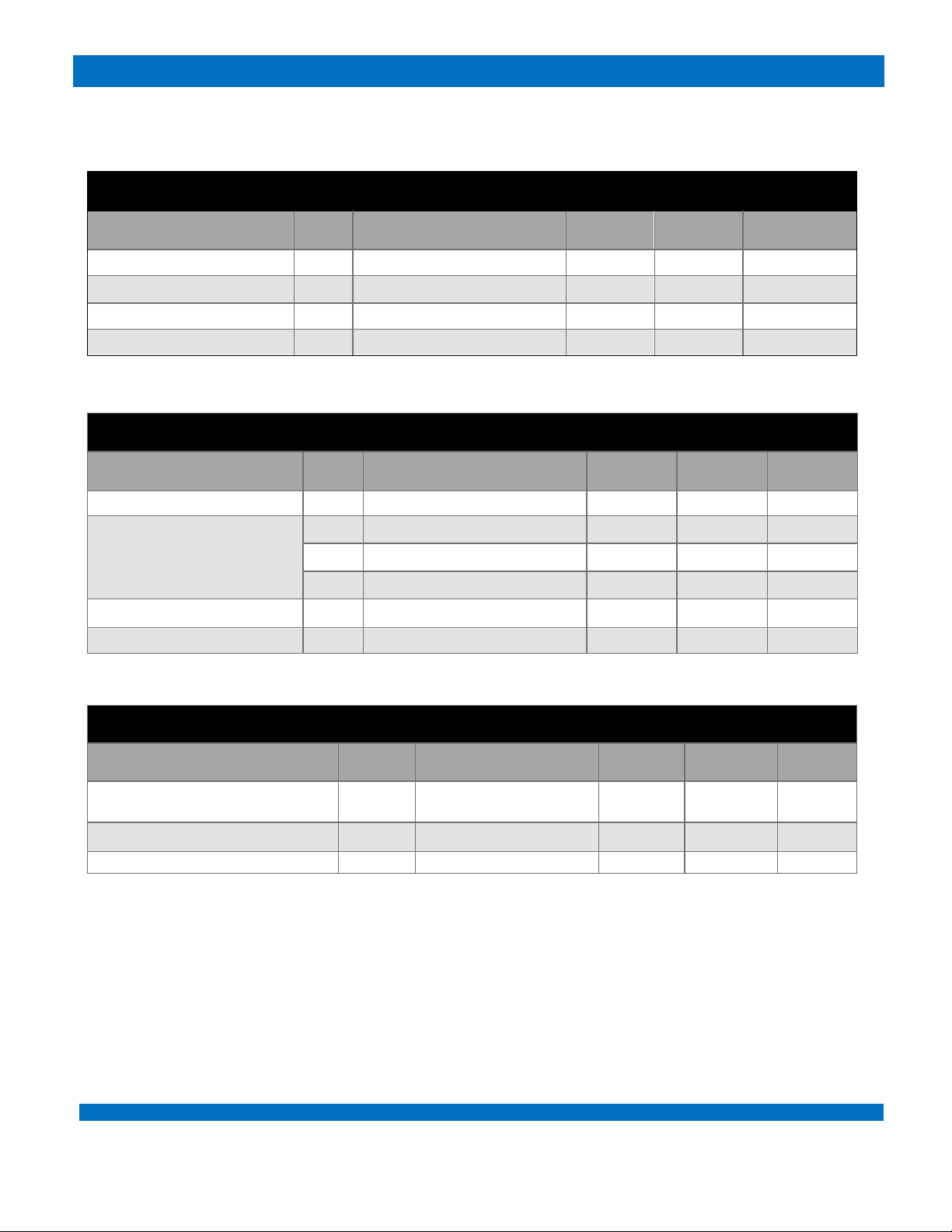
6 SPECIFICATIONS
SOLAR CELL STRING
Parameter
Unit
Condition
Min
Typ
Max
Voltage
V
25⁰C
9.32
Current
mA
25⁰C
1034
Power
W
25⁰C
9.63
Efficiency
%
29.5
TEMPERATURE SENSOR
Parameter
Unit
Condition
Min
Typ
Max
Range
°C
-55
150
Accuracy
°C
-25°C to 85°C
±0.5
±1.5
°C
-55°C to 125°C
±1
±2
°C
-55°C to 150°C
±1.5
Vcc
V
2.7
3.3
5.5
Quiescent Current
µA
50
75
SUN SENSOR
Parameter
Unit
Condition
Min
Typ
Max
Reverse Light Current
µA
EV =100lx
CIE illuminant A
0.03
0.04
0.09
Range of Spectral Bandwidth (λ0.5)
nm
430 to 610
Angle of Half Sensitivity
deg
±60°

SOLAR PANEL 40P6 –USER MANUAL
ENDUROSAT
10
7 PHYSICAL LOCATION OF SENSORS
The physical location of all the sensors are shown in figure 3.
Figure 3: Physical Location of the Sensors

SOLAR PANEL 40P6 –USER MANUAL
ENDUROSAT
11
8 MECHANICAL CHARACTERISTICS
The Solar Panel 40P6 should be mounted using bolts of type:
Torx - DIN965/ISO 7046-1 - M3 –Length: 6mm
The important dimensions of the solar panel are shown in figures 4, 5 and 6. All values are in mm.
STEP / PARASOLID files can be provided upon request.
Figure 4: Solar Panel 40P6 - Top Side (dimensions in mm)
SOLAR PANEL 40P6 –USER MANUAL
ENDUROSAT
12
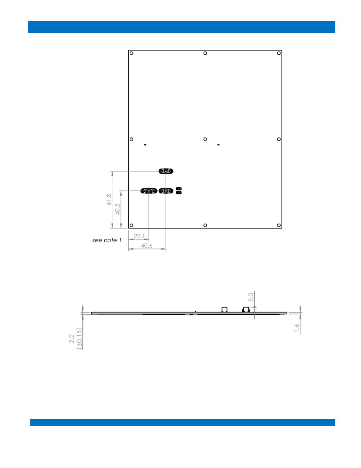
Figure 5: Solar Panel 40P6 - Bottom Side (connector location, dimension in mm)
Figure 6: Solar Panel 40P6 - Side View (dimensions in mm)
Note 1: Reference dimensions are taken to the center of the connectors

SOLAR PANEL 40P6 –USER MANUAL
ENDUROSAT
13
9 MATERIALS AND ASSEMBLY
The PCB material is FR4-Tg170. The production process follows quality standards:
•IPC-A-600H Ⅱ(Surface)
•IPC-A-6012 (Function)
•IPC-TM-650 (Test Method)
The component mounting follows quality standards:
•IPC-A-600 Acceptability of Printed Boards
•IPC-A-610Е Acceptability of Electronic Assemblies
•J-STD-001 Requirements for Soldered Electrical and Electronic Assemblies
•ISO 14644 Cleanrooms and Associated Controlled Environments
•IEC 61340 Electrostatics ESD: Protection of Electronic Devices from Electrostatic Phenomena
10 HANDLING AND STORAGE
Particular attention shall be paid to the avoidance of damage to the solar panel during handling,
storage and preservation. The handling of the solar panel should be performed in compliance with the
following instructions:
•Handle using PVC, latex, cotton (lint free) or nylon gloves.
•The environment where the solar panel will be handled shall meet the requirements for a class
environment 100,000, free of contaminants such as dust, oil, grease, fumes and smoke from
any source.
•Do not touch the solar cells on the solar panel.
•Solar panels must be handled by touching the PCB edges only.
•Solar panels shall be stored in such a manner as to preclude stress and prevent damage.
•To prevent the deterioration of the solar cells, then the solar panel shall be stored in a
controlled environment (i.e. the temperature and humidity levels shall be maintained within the
proper ranges):
oIdeal storage temperature range: 15ºC to 27ºC
oIdeal storage humidity range: 30% to 60% relative humidity (RH)
SOLAR PANEL 40P6 –USER MANUAL
ENDUROSAT
14
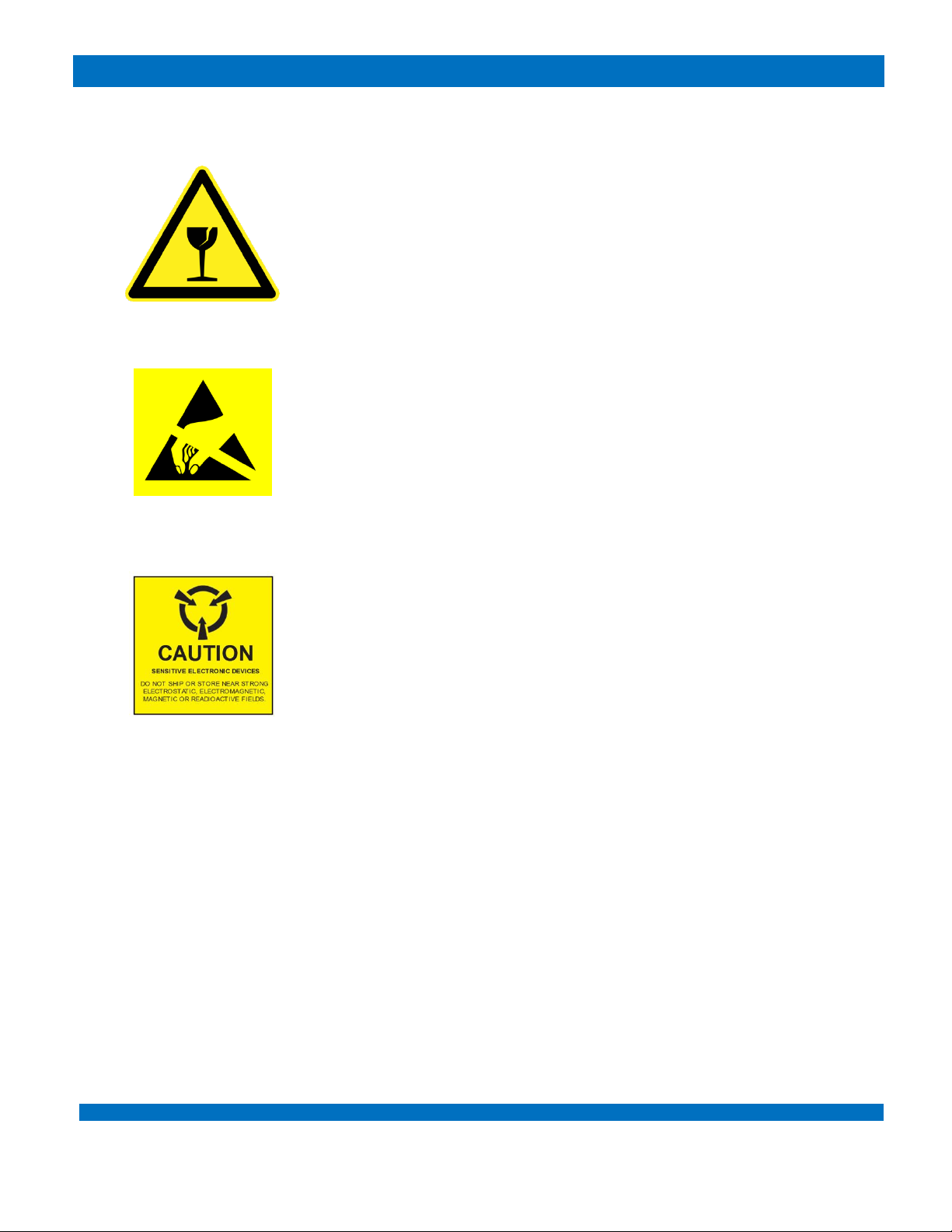
11 WARNINGS
This product uses very fragile components. Observe precautions
for handling.
This product uses semiconductors that can be damaged by
electrostatic discharge (ESD). Observe precautions for handling.
Sensitive electronic device. Do not ship or store near strong
electrostatic, electromagnetic, magnetic or radioactive fields.
Table of contents
Popular Solar Panel manuals by other brands

Technaxx
Technaxx TX-212 user manual

Sunna Design
Sunna Design Sol EVERGEN M Series installation guide

Dometic
Dometic NDS BS 165WP Installation and operating manual

RAKwireless
RAKwireless 7249 installation guide

Sonnenkraft
Sonnenkraft SKR500 DBA20R manual

Solfex
Solfex IRC 2.1 System installation, commissioning and maintenance manual


PowerTraveller
PowerTraveller Solargorilla user guide

Tamarack Solar
Tamarack Solar UNI-GR/90 installation manual
/F-B installation manual")
Astronergy
Astronergy CHSM60M(DG)/F-B installation manual

Chicago Electric
Chicago Electric 44768 Assembly and operating instructions

KAIROS
KAIROS CF 2.0-1 manual

PHOTOWATT
PHOTOWATT PW72HT-C installation manual