Enerdrive Lithium Power Pack Series User manual

Page 2
and created a COMPLETE Lithium Battery & Installation System so your Li-Ion battery bank is fully
protected. Most importantly, our system is designed to give the maximum performance, longevity and
SAFETY in your valuable installations.
Be aware that the market is abuzz with the hot topic of Lithium Ion Batteries; and we can tell you from
our testing to date that all the hype of their performance and capabilities is TRUE. However what we
can also inform you is that all the stories of their ‘Issues’ are unfortunately also true. However the so
called “issues’ of lithium can be avoided with some very basic rules about protection.
• Never go over voltage whilst charging them
• Never let them go ‘Dead’ Flat
• Keep the individual cells ‘Balanced’
What this lesson taught us is if we were to develop our lithium program – IT HAD TO BE DONE RIGHT.
So we developed our own Lithium Power Pack for the Australian market with the emphasis on ‘built
like a tank’; and even to the extent of being a little bit ‘overkill’ on the packaging and protection.
So how does our system actually work?
The Advance BMS relay driver is designed to take multiple signal input connections from the ePRO
Plus battery meter for low state of charge (SOC%) & system voltage & Hi/Low Cell voltage from the
batteries Active Cell Balancer unit and control all charging and discharging sources connected to the
lithium battery system.
System Program Selection Switch;
The Enerdrive Advanced BMS Relay Driver has 2 pre-programed settings.
In the event of low SOC% and/or voltage reaches the pre-set level, the program will shut down the
charging sources (solar/vehicle) and the inverter/charger before disengaging the main battery relay,
turning off the whole electrical system to protect the battery. The program will then switch on the
signal for all charging sources. When AC power is applied to the Combi, the AC charger will start once
the main latching relay is re-engaged. To re-engage the main battery relay, press in the Yellow button
on top of the main battery relay.
PROGRAM A:
FOR SYSTEMS INSTALLED WITH ePOWER AC, DC2DC CHARGERS & ePOWER INVERTERS:
This program isolates the charging sources (solar/vehicle/mains charger) in the event of a battery cell
voltage being too high without turning the whole electrical system off. The Enerdrive Advanced BMS
Relay Driver will activate the TOR & output contacts that will cut out all charging sources for 10 minutes.
If the cell has not come back within range before 10 minutes, it will stay active for another 10 minutes and
repeat until the cell/s are within range. This setup allows the system loads to still be powered.
In the event of low SOC% and/or voltage, the main battery relay will disengage to protect the battery. All
charging sources (solar/vehicle/mains charger) will still be active to recharge the battery providing the sun is
up or the chargers are plugged in. To re-engage the main battery relay, press in the Yellow button on top of
the main battery relay. The Enerdrive Advanced BMS Relay Driver will turn the main battery relay OFF every 6
minutes if the SOC% on the battery monitor is still below the set point. So this may need to be reset a few
times before the SOC% set point reaches its re-engagement point.
FOR SYSTEMS INSTALLED WITH COMBI INVERTER/CHARGERS:
After 2 years of research, testing and proving, and a further 6+ years of infield sales, Enerdrive has designed
This program is used if the temperature sensor fails. By selecting Program B, the temperature sensor is
ignored allowing for operation of the system until you can replace the faulty temperature sensor.
Running this program will get you into “Limp-Home Mode” but you will have no temperature control on
the system thus leaving the lithium protection system compromised. Contact Enerdrive to arrange for a
replacement Temperature Sensor.
PROGRAM B:
The Enerdrive Advanced BMS Relay Driver will turn the main battery relay OFF every 6 minutes if the SOC%
on the battery monitor is still below the set point. So this may need to be reset a few times before the SOC%
set point reaches its re-engagement point.

Status LED
The Advanced BMS Relay Driver is equipped with a “Status” LED indicator to respond to certain
conditions that the Relay Driver is experiencing. Status condition is as follows;
No Status LED: All Components are operating under normal conditions
Flashing Green LED: The system has registered an alarm condition from Inputs 1 or 2 and
will activate LOW SOC/Low Cell safety program
Flashing Red LED: The System has registered an alarm condition via high cell voltage
(≥3.80V per cell) shutting down all charging circuits. When voltage drops below 3.60V per
cell, charge circuits will switch back on.
Solid Red LED: The System has registered an alarm condition via a high temperature (≥45˚C)
shutting down all charging circuits. When temperature drops below 45˚C, load circuits will
switch back on.
Flashing Red/Blue LED: The System has registered an alarm condition via a high temperature
(≥ 55˚C, load circuits will switch off.
4 x “TOR” Circuits – Programmed to control Enerdrive ePOWER AC & DC2DC Chargers, &
Morningstar Solar Controllers (Hi/Low Alarm Protection).
4 x Normally Open/Closed/Common Contacts (10 Amps Max) – programmed to switch
trigger contacts/relays connected to Alternators*, Chargers, Solar or DC/AC relays, cabinet cooling
fan and Combi Inverter/Charger Units. (Hi/Low Alarm Protection).
1 x Temperature Sensor input – to control charging/discharging circuits
*Requirements of Alternator must be assessed to determine if suitable for the application.
1 x Latching Rely Output – Used to shut down system loads to protect the battery from over
discharge.
Temperature Sensor
The temp sensor input is monitoring temperature via the connected sensor within the surrounding
space of the sensor. The system is programmed to act on pre-determined temperature readings to
control the output circuits. These programmed parameters are;
At ≥35°C, activates Output No 4 for controlling connected Cabinet Fan cooling.
At ≥45°C, activates TOR Controls 1-4 and Outputs 1-2 to shut down charging sources to protect
battery from overcharge in extreme heat conditions.
At ≥ 55°C, activates Latching Relay to disengage load circuit to protect battery from
overheating in extreme heat conditions. <55˚C this system will re-engage the latching relay to
power the application
At ≤0°C, activates TOR Controls 1-4 and Outputs 1-2 to shut down charging sources to protect
battery from charge input in extreme cold conditions.

Status LED
Flashing GREEN - LOW SOC% <24% or LOW CELL Voltage
<2.8/Cell (Load Shutdown)
Flashing RED - HIGH CELL Voltage >3.8V/Cell - Charger Shutdown
Solid RED - High Temp Charger Shutdown >45˚C
(Charger Shutdown)
Flashing RED/BLUE - Extreme Temp System Shutdown >55˚C
(Charge & Load Shutdown)
When Red LEDs are on, all output circuits
are disabling connected charge sources.
When Red LEDs are off, all output circuits
are within range and operating correctly.
When Red LEDs are on,
all output circuits are disabling
connected charge sources.
When Green LEDs are on, all input
circuits are within range and
operating correctly.
When one or more Green LEDs
are out, the input is receiving an alarm
signal from the connected equipment.
When Green LED is on, the connected
latching relay is engaged and operating
correctly.
When Green LED is off, the connected
latching relay is disengaged shutting
power to all output loads.
When Red LEDs are off,
all output circuits are within
range and operating correctly.
Program
Selector
Switch
(Set To Position A)
Temp Sensor
OUTPUT 4
When Red
ePRO Combi
Inverter
shutdown
(if connected)
Cabinet Cooling
Fan Control
Turns ON >35˚
Power
Input
Reserved
for Future Use

Page 6
What’s in the Enerdrive Lithium System?
To use the Enerdrive Lithium Power Pack you need to use a combination of items together. These are:
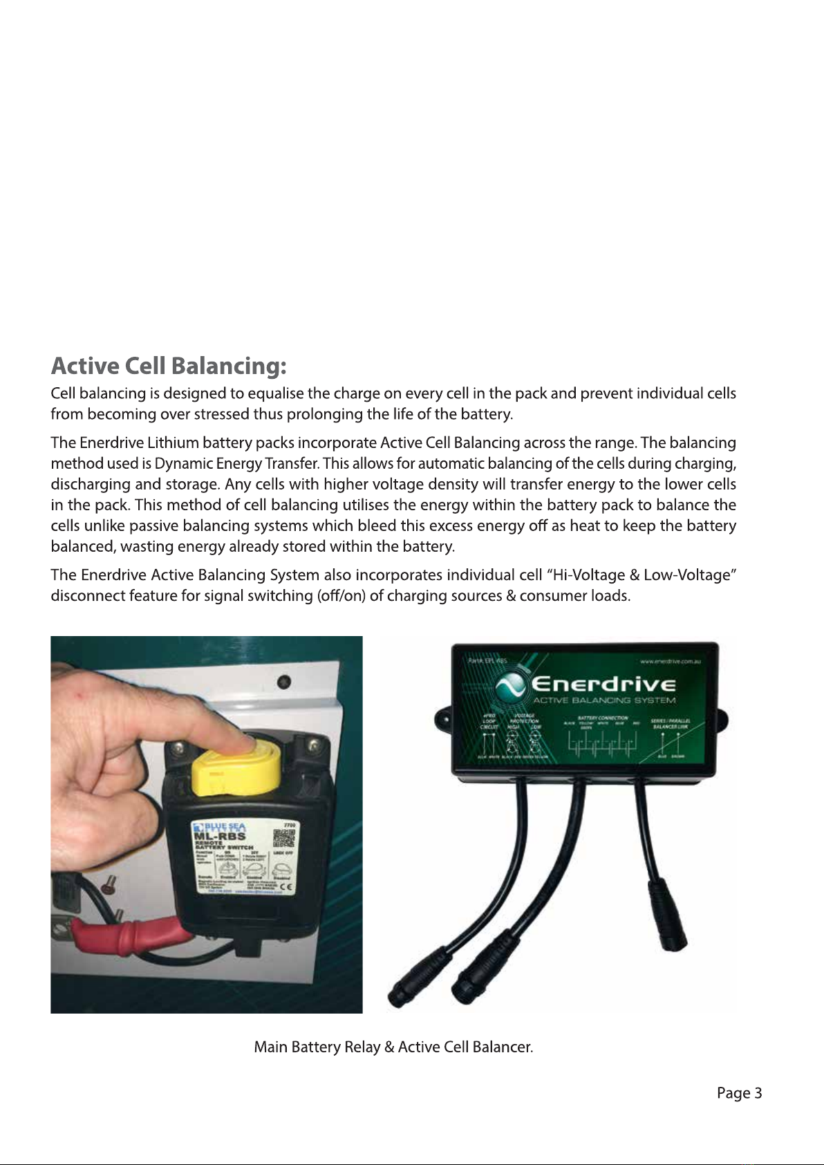
• The actual lithium power pack battery box including Active Balancing System.
• The Advance BMS controller board which includes
• The Advance BMS Relay Driver box
•
The ePRO Plus is our latest generation, highly advanced battery monitor. It consists of an intelligent
active shunt and a remote control and display unit (CDU). The shunt has a Grid Optimized footprint
for perfect integration with our DC Modular series of high current busbars and fuse holders.
The ePRO Plus battery monitor can measure DC currents up to 600Amps (500Amp continuous) and
voltages up to 70Vdc. So any lead- or lithium based battery from 12V up to 48V can be monitored.
•
A Blue Sea 500amp main battery latching relay which is activated by the ePRO Plus Battery Monitor
when the low state of charge (percentage is reached).
• A Class T Fuse for system protection.
• 70 - 120mm² Battery cable (depending on system) from the battery to the Connection Kit.
1Left key (<) or Previous value
2Menu or Enter key
3Right key (>) or Next value
4
5Alarm indicator
6Selected battery input indicator
7Value section for SoC (also for Function, Status and History parameter numbers)
8
discharge current (turning counter clockwise). The animation speed will also increase when the charge or discharge
current
clockwise) or a
increases.
Page 7
The ePRO Plus Battery Monitor has been pre-programmed at the factory to suit the selected Lithium
system and is software locked. There is no setup interaction required by the end user. For more user
information on the ePRO Plus Battery Monitor, please refer to the detailed instruction manual included
in your documentation package.
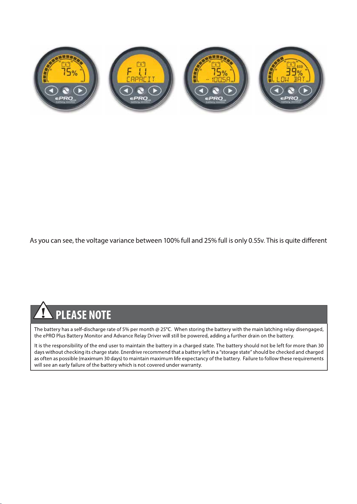
Voltages for Lithium batteries have a very narrow window compared to lead acid batteries. With all of
our testing over the last 6+ years, the Enerdrive Lithium battery standing voltage when fully charged
(with no loads running) will be between 13.35v-13.45v at 100% capacity.
When discharged to near 25% capacity remaining, the standing voltage will be between 12.90v-13.00v
to lead acid batteries where voltage can range from 12.72v at 100% to 11.88v at 20% capacity.
With Lithium, it is better and more accurate to work on the State of Charge Percentage (SOC%) to
determine your remaining battery capacity.
State of charge (%) Volt, Amp, Ah, time remaining,
temperature, Watts, and
maintenance hours.
Status or history readout Alarm activated (low battery
state of charge)

Page 8
BATTERY STORAGE INFORMATION:
IMPORTANT PLEASE READ:
When storing your Enerdrive lithium battery, even with the main Remote Battery Switch disengaged,
the ePRO PLUS Battery Monitor and Advanced BMS Relay Driver will still be powered, producing a small
constant drain on the lithium battery. Therefore, it is essential that you keep your Enerdrive lithium
battery charged when you are not using your vehicle/vessel. It is the responsibility of the end user to
maintain the Enerdrive lithium battery in a charged state.
Your lithium battery should not be left for more than 30 days without checking its charge state. Enerdrive
recommend that your lithium battery should ideally be checked and charged as often as possible to
maintain maximum life expectancy, especially if you leave any DC loads running. Failure to follow these
requirements could see an early failure of the battery, which is not covered under warranty.
When you are not using your Enerdrive lithium system it is strongly recommended that you
have access to AC power then leave your vehicle/vessel in the sun to allow your solar panels
(if installed) to keep the battery charged.
If you store your vehicle/vessel under cover and you don’t have access to AC power, then you must
prevent the battery from being discharged to a critical, potentially non-recoverable, state of charge.
Before your battery state of charge reaches 24% you must either connect your vehicle/vessel to AC
power or move it into the sun and allow the solar (if installed) to bring the battery up to a reasonable
state of charge. In either case, it would make sense to fully charge your lithium battery to 100% in order
to increase the period of time before you have to repeat this procedure.
If your vehicle/vessel is connected to AC power and is being left unattended for longer than 30 days,
and will not be checked by yourself, we recommend that you either ask someone to check on it regularly
while you are away or follow the long term storage procedure in the following pages.
Long Term Storage Switch
------ Failure to correctly store your lithium batteries will result in early battery failure --------
If you are intending to store your vehicle/vessel for more than 30 days,
it is recommended to shut down the entire DC electrical system. You
This switch is designed to completely isolate the Enerdrive lithium
battery from the DC electrical system, including the ePRO PLUS
battery monitor and Advanced BMS Relay Driver and will prevent
any external discharge of the lithium battery.

Page 9
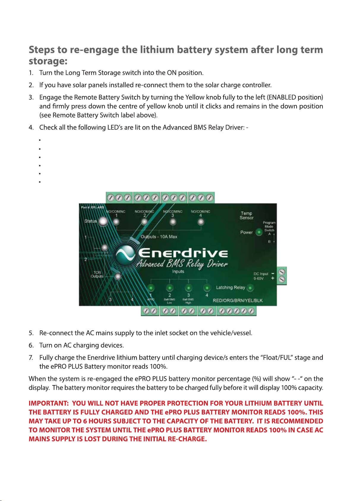
Page 10
Power
Input 1
Input 2
Input 3
Input 4 (if connected)
Latching Relay

Page 11
Troubleshooting the Lithium Battery System
Q: What if the battery monitor reads 24% or less or the battery voltage has reached 12.4v or less, and
the power has gone out?
Q: What if I see red LED’s on the “TOR & Outputs” of the Advanced Relay Driver?
A: If a battery cell goes Hi Voltage and cuts the HI Voltage loop wire then the Advanced BMS Relay
Status LED will flash RED and the Driver will activate the TOR & Output contacts (turning red) and
will drive the installed relay/contacts to cut out all charging sources (solar/vehicle/main charger) for
10 minutes. If the cell voltage has not come back within range before 10min, it will stay active for
another 10 minutes and repeat until the cell/s are within range.
A:
The battery has reached its maximum discharge and the main battery relay has dis-engaged to
protect the battery. Turn off all loads and turn on the charging sources. Once the percentage on
the ePRO Plus Meter reaches 28%, you can push the yellow button on the main battery relay until
it latches down to re-engage the main battery switch and monitor your loads. Keep charging
sources connected until the battery reaches maximum charge 100%.
Q: What if the main battery switch has tripped out, but the LED’s on Inputs 1-3 on the Advanced
BMS Relay Driver are Green and the battery monitor is 26% or higher in capacity?
A: This has happened because the system has registered 1 of 2 faults:
1: A high temperature condition has occurred above 55°C (status LED flashing Red/Blue) and shut
down the main battery relay to protect the system from an extreme high temperature situation.
Once the temperature reduces below 55°C the main battery relay will automatically switch itself back on.
2: The system has registered a low battery SOC ≤24% or low cell voltage ≤ 3.1V condition (Status LED
flashing Green) and shut down the main battery relay to protect the battery from over discharge.
If solar is connected to the system, once the SOC rises above 26% and the cell voltage increases
above 3.1V then inputs 1-3 will register a Green LED. At this point, push the yellow button on the
main battery relay until it latches down to re-engage the main battery switch and monitor your loads.
Switch on additional charging sources until the battery reaches maximum charge 100%
Q: What if the Status light is flashing Blue and the temperature is above 0°C?
A:
The Temperature Sensor has failed or become unplugged and the system has shut down the charge
sources. Check to make sure the sensor is plugged in correctly. If so, remove the Temperature Sensor
from the Advanced BMS Relay Driver and select Program B on the side of the Advanced BMS Relay Driver.
Refer “Program B” on page ##
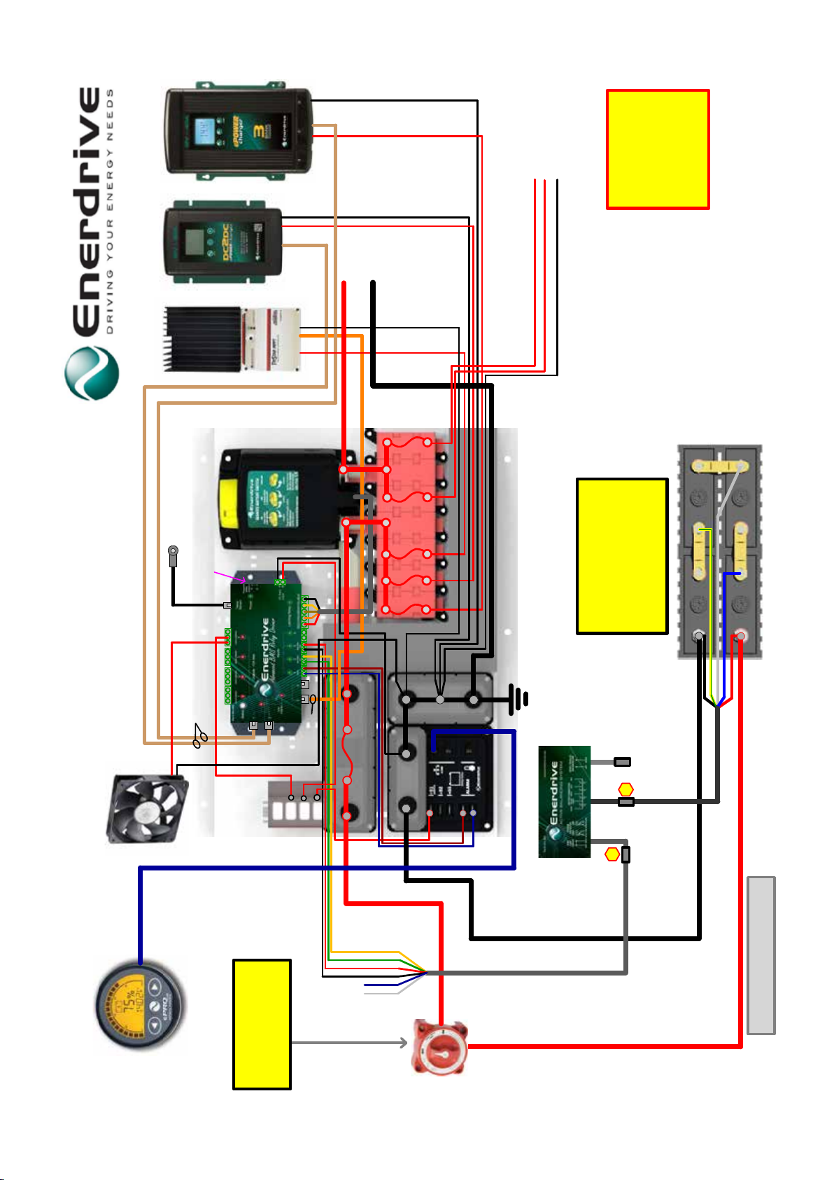
DC LOADS +
EN3TOR-G2
Set DipSwitch to:
Standard Program
If using Dual Batteries in
Parallel or Series please
refer to:
* Parallel 12v setup drawing
* Series 24v setup drawing
NOTE:
1.Voltage protection circuit must
be connected prior to connecting
the Battery connection Plug.
2. Never disconnect Battery
connection wires from the battery
while the lead is connected to the
EPL-ABS box.
WARNING!
EPL-ABS
14/12/2018
Battery +
Battery -
+
-
RED
BLUE
WHITE
YELLOW/GREEN
BLACK
GREEN
BLUE
BLACK
RED
WHITE
YELLOW
Inverter +
Inverter -
DC LOADS +
COMMON NEG
EPL-ABS
Voltage
Protection
Circuit
Battery
Connection
Balancer
Link N/A
Lithium Setup - ePOWER Single 12v - 2018-G2
SR-TS-TOR-G2
TOR Output SR-TS-TOR-G2
Wire to:
RTS Terminal
2
1
1A
10A
NOTE:
Long term storage switch.
Only turn this switch OFF once the batteries
are fully charged, the Yellow Latching Relay
is disengaged and all charging sources have
been shut down correctly.
Min 95mm Cable with a Max length of
1.5m from Battery to Connection Board.
2
Enerdrive has provided this drawing as a guide only
and installers must ensure the system is installed to the
local requirements for fuse protection and wire sizing.
If you have any questions please call;
Enerdrive on 07 3390 6900
Temp Sensor
5A
Optional Cabinet Fan
Output 4 Turns on when
Temp Sensor >35
°C
EN3TOR-G2
Plug into BTS
EN3TOR-G2
Plug into BTS

DC LOADS +
EN3TOR-G2
Set DipSwitch to:
Standard Program
12/12/2018
GREEN
BLUE
BLACK
RED
WHITE
YELLOW
Inverter +
Inverter -
DC LOADS +
COMMON NEG
Lithium Setup - ePOWER Dual 12v - 2018-G2
SR-TS-TOR-G2
SR-TS-TOR-G2
Wire to:
RTS Terminal
1A
10A
NOTE:
Long term storage switch.
Only turn this switch OFF once the batteries
are fully charged, the Yellow Latching Relay
is disengaged and all charging sources have
been shut down correctly.
Enerdrive has provided this drawing as a guide only
and installers must ensure the system is installed to the
local requirements for fuse protection and wire sizing.
If you have any questions please call;
Enerdrive on 07 3390 6900
Temp Sensor
5A
Optional Cabinet Fan
Output 4 Turns on when
Temp Sensor >35
°C
EN3TOR-G2
Plug into BTS
EN3TOR-G2
Plug into BTS
GREEN
BLUE
BLACK
RED
WHITE
YELLOW
EPL-ABS
Battery +
Battery -
+
-
Battery +
Battery -
RED
BLUE
WHITE
YELLOW/GREEN
BLACK
+
-
RED
BLUE
WHITE
YELLOW/GREEN
BLACK
EPL-ABS
Voltage
Protection
Circuit
Battery
Connection
Balancer
Link N/A
Voltage
Protection
Circuit
Battery
Connection
Balancer
Link N/A
2
12
13
3
Min 95mm Cable with a Max length of
1.5m from Battery to Connection Board.
2
Battery cables must be of equal length and size between
Batteries and busbars to keep the batteries balanced.
1.Voltage protection circuit must
be connected prior to connecting
the Battery connection Plug.
2. Never disconnect Battery
connection wires from the battery
while the lead is connected to the
EPL-ABS box.
3. Only connect Balance wire once
Battery Conection wires and plugs
are connected.
WARNING!
EPL-ABS

6C6P
Splitter
Box
6C6P
Splitter
Box
DC LOADS +
EN3TOR-G2 Set DipSwitch to:
Standard Program
13/12/2018
GREEN
BLUE
BLACK
RED
WHITE
YELLOW
DC LOADS +
COMMON NEG
Lithium Setup - ePRO 1600 Single 12v - 2018-G2
SR-TS- TOR-G2
SR-TS-TOR-G2
Wire to:
RTS Terminal
1A
10A
NOTE:
Long term storage switch.
Only turn this switch OFF once the batteries
are fully charged, the Yellow Latching Relay
is disengaged and all charging sources have
been shut down correctly.
Enerdrive has provided this drawing as a guide only
and installers must ensure the system is installed to the
local requirements for fuse protection and wire sizing.
If you have any questions please call;
Enerdrive on 07 3390 6900
Temp Sensor
5A
Optional Cabinet Fan
Output 4 Turns on when
Temp Sensor >35
°C
EN3TOR-G2
Plug into BTS
Battery +
Battery -
+
-
RED
BLUE
WHITE
YELLOW/GREEN
BLACK
EPL-ABS
Voltage
Protection
Circuit
Battery
Connection
Balancer
Link N/A
2
1
3
1.Voltage protection circuit must
be connected prior to connecting
the Battery connection Plug.
2. Never disconnect Battery
connection wires from the battery
while the lead is connected to the
EPL-ABS box.
3. Only connect Balance wire once
Battery Conection wires and plugs
are connected.
WARNING!
EPL-ABS
Min 70mm Cable with a Max length of
1.5m from Battery to Connection Board.
2
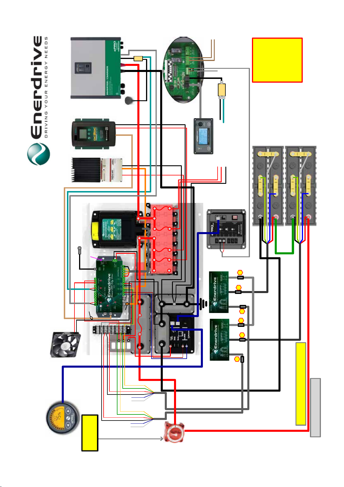
Inverter +
Inverter -
EPC-TOR
Twin Core to: Trigger 1/COM
Temp Sensor
(From Output 3) EPC-TOR
Temp Sensor (from Output 1 or 2)
Twin Core to
Trigger 1/COM
Inside Combi
Twin Core
Wire to:
Trigger 1/COM

6C6P
Splitter
Box
6C6P
Splitter
Box
DC LOADS +
EN3TOR-G2 Set DipSwitch to:
Standard Program
13/12/2018
GREEN
BLUE
BLACK
RED
WHITE
YELLOW
DC LOADS +
COMMON NEG
Lithium Setup - ePRO 3000 Single 12v - 2018-G2
SR-TS- TOR-G2
SR-TS-TOR-G2
Wire to:
RTS Terminal
1A
10A
NOTE:
Long term storage switch.
Only turn this switch OFF once the batteries
are fully charged, the Yellow Latching Relay
is disengaged and all charging sources have
been shut down correctly.
Enerdrive has provided this drawing as a guide only
and installers must ensure the system is installed to the
local requirements for fuse protection and wire sizing.
If you have any questions please call;
Enerdrive on 07 3390 6900
Temp Sensor
5A
Optional Cabinet Fan
Output 4 Turns on when
Temp Sensor >35
°C
EN3TOR-G2
Plug into BTS
Battery +
Battery -
+
-
RED
BLUE
WHITE
YELLOW/GREEN
BLACK
EPL-ABS
Voltage
Protection
Circuit
Battery
Connection
Balancer
Link N/A
2
1
3
1.Voltage protection circuit must
be connected prior to connecting
the Battery connection Plug.
2. Never disconnect Battery
connection wires from the battery
while the lead is connected to the
EPL-ABS box.
3. Only connect Balance wire once
Battery Conection wires and plugs
are connected.
WARNING!
EPL-ABS
Inverter +
Inverter -
EPC-TOR
Twin Core to: Trigger 1/COM
Temp Sensor
(From Output 3) EPC-TOR
Temp Sensor
(from Output 1 or 2)
Twin Core to
Trigger 1/COM
Inside Combi
Twin Core
Wire to:
Trigger 1/COM
AC Switch for
Non essental
loads i.e Aircon
AirCon >%
(from Alarm Expander)
Twin Core to
Trigger 2/COM
Optional
Alarm Expander
Min 95mm Cable with a Max length of
1.5m from Battery to Connection Board.
2

6C6P
Splitter
Box
6C6P
Splitter
Box
DC LOADS +
EN3TOR-G2 Set DipSwitch to:
Standard Program
13/12/2018
GREEN
BLUE
BLACK
RED
WHITE
YELLOW
DC LOADS +
COMMON NEG
Lithium Setup - ePRO 3000 Dual 12v - 2018-G2
SR-TS- TOR-G2
SR-TS-TOR-G2
Wire to:
RTS Terminal
1A
10A
NOTE:
Long term storage switch.
Only turn this switch OFF once the batteries
are fully charged, the Yellow Latching Relay
is disengaged and all charging sources have
been shut down correctly.
Enerdrive has provided this drawing as a guide only
and installers must ensure the system is installed to the
local requirements for fuse protection and wire sizing.
If you have any questions please call;
Enerdrive on 07 3390 6900
Temp Sensor
5A
Optional Cabinet Fan
Output 4 Turns on when
Temp Sensor >35
°C
EN3TOR-G2
Plug into BTS
GREEN
BLUE
BLACK
RED
WHITE
YELLOW
EPL-ABS
Battery +
Battery -
+
-
Battery +
Battery -
RED
BLUE
WHITE
YELLOW/GREEN
BLACK
+
-
RED
BLUE
WHITE
YELLOW/GREEN
BLACK
EPL-ABS
Voltage
Protection
Circuit
Battery
Connection
Balancer
Link N/A
Voltage
Protection
Circuit
Battery
Connection
Balancer
Link N/A
2
12
13
3
Min 95mm Cable with a Max length of
1.5m from Battery to Connection Board.
2
Battery cables must be of equal length and size between
Batteries and busbars to keep the batteries balanced.
1.Voltage protection circuit must
be connected prior to connecting
the Battery connection Plug.
2. Never disconnect Battery
connection wires from the battery
while the lead is connected to the
EPL-ABS box.
3. Only connect Balance wire once
Battery Conection wires and plugs
are connected.
WARNING!
EPL-ABS
Inverter +
Inverter -
EPC-TOR
Twin Core to: Trigger 1/COM
Temp Sensor
(From Output 3) EPC-TOR
Temp Sensor
(from Output 1 or 2)
Twin Core to
Trigger 1/COM
Inside Combi
Twin Core
Wire to:
Trigger 1/COM
AC Switch for
Non essental
loads i.e Aircon
AirCon >%
(from Alarm Expander)
Twin Core to
Trigger 2/COM
Optional
Alarm Expander
6C6P
Splitter
Box
6C6P
Splitter
Box
DC LOADS +
EN3TOR-G2 Set DipSwitch to:
Standard Program
13/12/2018
GREEN
BLUE
BLACK
RED
WHITE
YELLOW
DC LOADS +
COMMON NEG
Lithium Setup - ePRO 3500 24v - 2018-G2
SR-TS- TOR-G2
SR-TS-TOR-G2
Wire to:
RTS Terminal
1A
10A
NOTE:
Long term storage switch.
Only turn this switch OFF once the batteries
are fully charged, the Yellow Latching Relay
is disengaged and all charging sources have
been shut down correctly.
Enerdrive has provided this drawing as a guide only
and installers must ensure the system is installed to the
local requirements for fuse protection and wire sizing.
If you have any questions please call;
Enerdrive on 07 3390 6900
Temp Sensor
5A
Optional Cabinet Fan
Output 4 Turns on when
Temp Sensor >35
°C
EN3TOR-G2
Plug into BTS
GREEN
BLUE
BLACK
RED
WHITE
YELLOW
EPL-ABS
Battery +
Battery -
+
-
Battery +
Battery -
RED
BLUE
WHITE
YELLOW/GREEN
BLACK
+
-
RED
BLUE
WHITE
YELLOW/GREEN
BLACK
EPL-ABS
Voltage
Protection
Circuit
Battery
Connection
Balancer
Link N/A
Voltage
Protection
Circuit
Battery
Connection
Balancer
Link N/A
2
12
13
3
Min 50mm Cable with a Max length of
1.5m from Battery to Connection Board.
2
Battery cables must be of equal length and size between
Batteries and busbars to keep the batteries balanced.
1.Voltage protection circuit must
be connected prior to connecting
the Battery connection Plug.
2. Never disconnect Battery
connection wires from the battery
while the lead is connected to the
EPL-ABS box.
3. Only connect Balance wire once
Battery Conection wires and plugs
are connected.
WARNING!
EPL-ABS
Inverter +
Inverter -
EPC-TOR
Twin Core to: Trigger 1/COM
Temp Sensor
(From Output 3) EPC-TOR
Temp Sensor
(from Output 1 o 2)
Twin Core to
Trigger 1/COM
Inside Combi
Twin Core
Wire to:
Trigger 1/COM
AC Switch for
Non essental
loads i.e Aircon
AirCon >%
(from Alarm Expander)
Twin Core to
Trigger 2/COM
Optional
Alarm Expander
3500va 24volt 70a
24V

Page 19
Lithium Battery Warranty: Two Year Limited Warranty
Our goods come with guarantees that cannot be excluded under the Australian Consumer Law. You are
entitled to a replacement or refund for a major failure and for compensation for any other reasonably
foreseeable loss or damage. You are also entitled to have the goods repaired or replaced if the goods
fail to be of acceptable quality and the failure does not amount to a major failure.
The limited warranty program is the only one that applies to this unit, and it sets forth all the responsibilities
of Enerdrive. There is no other warranty, other than those described herein. Any implied warranty of
this warranty.
Enerdrive Pty Ltd warrants its Lithium batteries (hereafter referred to as “Battery”) to be free of defects
in material and workmanship for the following Applicable Warranty Period:
• 1 year for Industrial & Commercial Use
•
2 years for marine pleasure vessel and automotive applications in cycling and non-cycling applications.
The battery is warranted, to the original purchaser only, to be free of defects in materials and
workmanship for two years from the date of purchase without additional charge. The warranty
does not extend to subsequent purchasers or users other than OEM applications.
•
An additional 24 months Pro-Rata warranty is included in the battery. The pro-rated price is calculated
as a percentage of the current suggested retail price. Pro-Rata warranty applicable to original end
user only.
Enerdrive does not warrant the battery for use in any residential system sold with the intent or purpose
The Enerdrive ePRO Plus battery monitor that is standard with every Lithium-Ion battery kit is pre-
The warranty does not cover a battery reaching its normal end of life which may occur prior to the
warranty period stated above. Depending on the application a battery can reach its normal end of life
before the end of the warranty period.
to have reached its normal end of life if the application uses up all of these cycles / amp-hours, regardless
claim if it determines the battery to be at its normal end of life, even if the claim is lodged within the
The Applicable Warranty Period begins from the date of purchase with original receipt, or, if no receipt
is available, from Enerdrives invoice / shipping date.
Batteries determined to meet the conditions of this warranty will be replaced free of charge if, at the
sole discretion of Enerdrive, adjustment is necessary due to defect in material or workmanship. Batteries
for warranty replacement consideration are to be returned to the original supplying distributor/dealer.
Batteries replaced under the warranty provisions will be shipped with a replacement warranty sticker
and carry only the remainder of the original Applicable Warranty Period.
The battery is not designed or warranted in the following areas:
• The Battery is NOT to be used in any Aviation aircraft application.
• The Battery is NOT to be used in any lifesaving applications
• The Battery is NOT to be exported to USA/Canada and their territories
•
Lorem ipsum
Page 20
PLEASE NOTE
The battery has a self-discharge rate of 5% per month @ 25°C. When storing the battery with the
main latching relay disengaged, the ePRO Plus Battery Monitor and Advance Relay Driver will still
be powered adding a further drain on the battery.
It is the responsibility of the end user to maintain the battery in a charged state. The battery should
not be left for more than 30 days without checking its charge state. Enerdrive recommend that a
battery left in a “storage state” should be checked and charged every 30 days to maintain maximum
life expectancy of the battery. Failure to follow these requirements will see an early failure of the
battery which is not covered under warranty.
General Provisions:
Enerdrives Pty Ltd has no obligation under the limited warranty herein in the event the battery is
damaged or destroyed as a result of one or more of the following:
• Wilful abuse, misuse, physical damage, neglect or if the decorative cover has been removed.
•
penetration or opening of the battery case in any manner.
•
The supplied Enerdrive ePRO Plus battery monitor is pre-programmed by Enerdrive if and any
•
The battery MUST be installed in an upright position. Installing it upside down or laid on its side
will void warranty.
•
Overcharging, undercharging, charging or installing in reverse polarity, improper maintenance,
allowing the battery to be deeply discharged via a parasitic load or mishandling of the battery such
as but not limited to using the terminals for lifting or carrying the battery.
•
between 13.5V and 14.5V (no lower than 13.0V and no higher than 14.7V) will cause early failure of the
battery. Use of such chargers with the battery will also void the battery’s warranty. For applications
where an alternator is present, the alternator must deliver between 13.5V and 14.2V when measured
at the Battery’s terminals. Alternators that do not have a regulated charge between 13.5V and 14.2V
(no lower than 13.0V and no higher than 14.7V) will cause early failure of the battery. Use of such
alternators with the battery will also void the batteries warranty.
•
All Enerdrive batteries are supplied with an additional battery installation kit. Failure to install or
properly install the battery and its installation kit will void the warranty
•
Repair or attempted repair of the battery by anyone other than an authorized Enerdrive representative
shall void this warranty.
•
Normal or accelerated deterioration in the electrical qualities due to operating or application
conditions.
•
If the battery is used for an application that requires higher cranking power or a greater reserve
rating than the battery is designed to deliver, or the battery capacity is less than the battery capacity
designed.
Lorem ipsum

Page 21
•
Prolonged storage of the battery with either no charge or a parasitic consumption load applied
disconnecting the battery to prevent irreversible damage to the battery.
• A battery with an open circuit voltage (OCV) of equal to or less than 10.0V will be deemed as over
discharged and void warranty due to misuse and/or neglect.
WARNING
Do NOT use any type of oil, organic solvent, alcohol, detergent, strong acids, strong alkalis, petroleum-
cause permanent damage to the battery covers and end plates and will void the warranty.
Return and/or Repair Policy
If you are experiencing any problems with your unit, please contact our customer service department
at support@enerdrive.com.au or Phone 1300 851 535 before returning product to retail store. After
speaking to a customer service representative, if products are deemed nonworking or malfunctioning,
the product may be returned to the purchasing store within 30 days of original purchase. Any defective
unit that is returned to Enerdrive within 30 days of the date of purchase will be replaced free of charge.
If such a unit is returned more than 30 days but less than two years from the purchase date, Enerdrive
will repair the unit or, at its option, replace it, free of charge. If the unit is repaired, new or reconditioned
replacement parts may be used, at manufacturer’s option. A unit may be replaced with a new or
reconditioned unit of the same or comparable design. The repaired or replaced unit will then be
warranted under these terms for the remainder of the warranty period. The customer is responsible
for the shipping charges on all returned items back to Enerdrive.
Limitations
This warranty does not cover damage or defects resulting from normal wear and tear (including chips,
scratches, abrasions, discolouration or fading due to usage or exposure to sunlight), accidents, damage
during shipping to our service facility, alterations, unauthorized use or repair, neglect, misuse, abuse,
If your problem is not covered by this warranty, contact our Support Team at support@enerdrive.com.
au or phone 1300 851 535 for general information if applicable.
Table of contents


