Feider Machines FPS500 User manual
ORIGINAL INSTRUCTIONS
Portable Power Pack
Operation Manual
FPS500/FPS1000
Thanks for your selection of our portable power pack.
Please read the manual carefully and save it for future
reference to ensure that you could use this product properly
and safely.
BUILDER SAS
32, rue Aristide Bergès - ZI 31270 Cugnaux – France
MADE IN PRC

CONTENTS
Ⅰ
Safety Disclaimer
Main Parts and
1
Ⅱ
Accessories
1
Ⅲ
Function Diagram
2
Ⅳ
Use Instructions
4
Ⅴ
Operation Guide
4
Ⅵ
Parameters
8
Ⅶ
Use Environment
9
ⅧPrecautions 9
ⅨWarranty Description 10
ⅩTroubleshooting 11

ⅠSafety Disclaimer
II
Main Parts and Accessories
DC
Input
(
12
LED Displa y
BA T T E R Y
BATTE R Y
OUT P U T
L O A D
Lig
Mh
atin
Sw
Siw
tc
it
h
Autom
obile
DC Output
(
12V
)
3A
DCControl QC3
.
0
Button
5V2
.
1A
3A
MAX
.
7A
5V2
.
1A
12V
3A
5V2
.
1A
This product is a safe, portable, stable and eco - friendly
power storage system. Which can be used in camp, boat trip,
rescue etc., and provide you a portable and sustainable green
power solution. Also, multiple AC outlets are included which can
charge fan, projector, refrigerator, computer etc., and 12V DC
outlet for LED like usage. This unit can be charged by accessory
AC charger or solar panel.
Users should read this manual carefully before using and maintaining.
Improper installation or misuse may cause danger to the user or damage
to this product.
Main Part 1:
Product*1PCS
Accessory 1:
AC Charger*1PCS
Accessory 2:
AC Charging
Line*1PCS
AWG
DC Output
(
12V
)
USB Output
Automobile
DC Input
(
12V
)
④
DC Input
(
12V
)
LED Display
BATTERY
BATTERY
O U TT PP U TT
⑪
①
③
LL O AA D
Max
.
5A
100%
Ligh
Ma
t
in
S
SS
w
wiit
t
c
c
h
h
Sw
M
it
a
c
LLh
i
i
g
n
ht
S
Sw
w
iy
i
c
t
h
ch
⑩
DC Output
(
12V
)
3A
DC Control
Button
USB Output
QC3
..
0
Automobile
Starter
DC
12V/10A
5V2
..
1
A
3A
⑤
MAX
.
7A
5V2
..
1
A
3A
12V
5V2
..
1
A
⑨
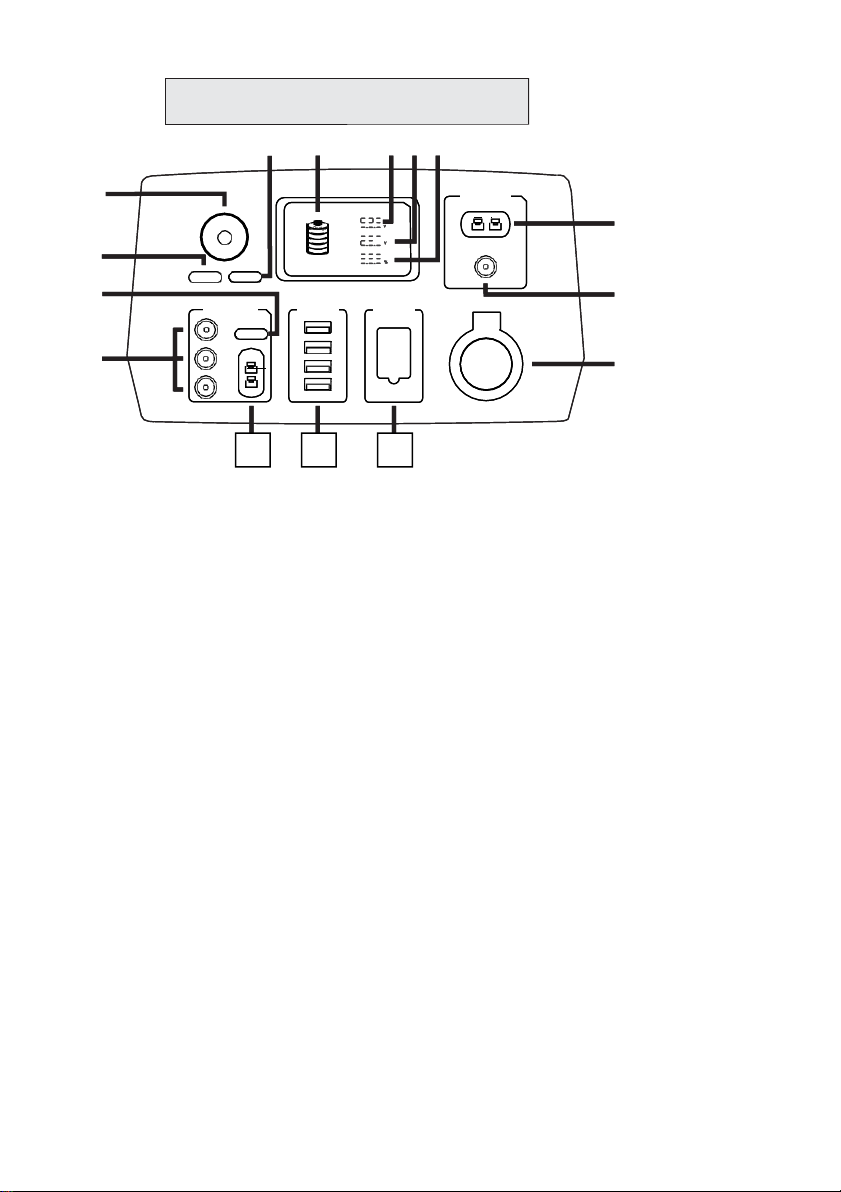
ⅢFunction Diagram
②
⑮ ⑭⑬⑫
⑥ ⑦
1)①Main Switch: Controls the system to turn on or off all output functions of the system.
2)②Light Switch: Control the LED light.
3)
③DC Switch: Control DC 12V 3A and DC 7A output connections.
4)
④Light: LED 3W high-beam Light.
5)
⑤DC Audio Outlet: DC 12V 3A outlet * 3pcs.
6)
⑥DC Anderson Outlet: DC 12V 7A outlet *1pcs.
7)
⑦USB Outlet: 1pcs QC3.0 plus 3pcs USB2.1A terminal,apply for fast charging and.
can charge Ipad and cell phone in the same time.
8)
⑧Automobile Starter: For 12V small car starting.
9)
⑨12V DC Outlet Socket:For 12V DC cigarette type connected load.
10)
⑩DC Charging Input Connection: DC connection socket for this battery charging.
11 )⑪DC Anderson Input Charging Connection: DC connection socket for this
battery charging.
12)
⑫Output Load Voltage Percentage: Displays percentage of output voltage,
range is from 0% to 100%.
13)
⑬Output Voltage: Display outputvoltage.
14)
⑭Battery Voltage: Displays current battery voltage value.
15)
⑮Battery Capacity: Displays battery capacity from 0% to 100%.
2
6
7
8
AC OUTPUT
⑱
FUSE
⑰
⑯
AC OUTPUT
⑱
FUSE
⑰
⑯
AC OUTPUT
⑱
FUSE
⑰
⑯
AC OUTPUT
⑱
FUSE
⑰
⑯
AC OUTPUT
⑱
FUSE
⑰
⑯
AC OUTPUT
⑱
FUSE
⑰
⑯
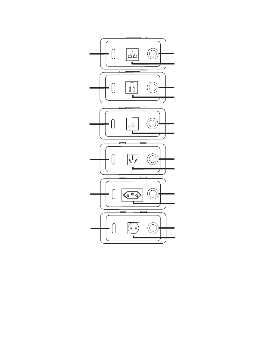
Note: Each country outlets` requirement is different, according to your own
needs to select the corresponding socket diagram.
16)⑯
17)⑰
18)⑱
AC Output Socket: Output is marketing value AC100V -120V or AC 220V-240V.
Fuse: Fuse will be disconnected when the load power exceeds the capacity
of the product.
AC Output Switch: Control AC output function to on or off.
3

④
LE
D
D D
i
i
s
sp l
p
ay
lay
DC Input
(
12V
)
Max 20A
BATTERY
BATTERY
O U T PU T
①
L O A D
Max
.
5A
100%
Ligh
Ma
t
in
S
S
w
w
i
it
t
c
c
h
h Ma
Li
i
g
n
ht
S
Sw
w
iy
i
c
t
h
ch
DC Output
(
12V
)
3A
DC Control
Button
USB Output
QC3
.
0
Automobile
Starter
DC
12V/10A
3A
MAX
.
7A
5V2
.
1A
5V2
.
1A
3A
12V
5V2
.
1A
ⅤOperation Guide
ⅣUse Instructions
1)
Theory of energy storage system: System converts energy from battery to electric
energy for DC or AC use.
2)
Theory of DC output: System converts the energy in the battery into electric
energy for DC use.
3)
Theory of AC output:System converts the energy in the battery into
electric energy for AC use.
4)
Theory of DC input:The energy storage system charges the battery with the
energy from the solar charging panel or other output of DC charger.
5)
The system uses lithium battery,for safety,in leaving the factory,the battery
has 30%to 50%of capacity.Before first use, it is recommended filling up with power
after full discharge.
6)
When the battery capacity is shown to be 20%, the system is likely to be cut off.
It is recommended to stop using and recharge before the battery reused.
7)
When the battery is 20%, normally it takes 4-6 hours to fill the battery under normal
charging conditions.
8)
Non-manufacturer-equipped charging wires and chargers may cause battery failure
or damage.
②
When need to start function ④light,should press function ①main switch in turn,
then press function ②light switch.When function ①main switch needs to be kept
on, the function ④light can be controlled separately by function ②light switch.
4

LED Display
①
Ligh
Ma
t
in
S
S
w
w
i
it
t
c
c
h
h Ma
Li
i
g
n
ht
S
Sw
w
iy
i
c
t
h
ch
③
DC Output
(
12V
)
3A
DC Control
Button
3A
MAX
.
7A
3A
BATTERY
100%
USB Output
QC3
.
0
5V2
.
1A
5V2
.
1A
5V2
.
1A
BATTERY
O U TP U T
L O A D
Automobile
Starter
DC Input
(
12V
)
Max 20A
Max
.
5A
DC
12V
12V/10A
⑥
When need to start function ⑤and ⑥DC outlets, should press ①main switch in turn,
then press ③DC switch. If function ①main switch needs to be kept on, The ⑤and
⑥DC outlet can be controlled separately by function ③DC switch. Function ⑤and
⑥DC outlet have over-load protection, which means there is no output when the load
is overloaded.
LED Displ ay
①
Ligh
Ma
t
in
S
S
w
w
i
it
t
c
c
h
h Ma
Li
i
g
n
ht
S
Sw
w
iy
i
c
t
h
ch
BATTERY
100%
BA TT E R Y
OU TP UT
LO A D
DC Input
(
12V
)
Max
.
5A
DC Output
(
12V
)
3A
DC Control
Button
3A
MAX
.
7A
3A
USB Output
QC3
.
0
5V2
.
1A
5V2
.
1A
5V2
.
1A
Automobile
Starter
DC
12V
12V/10A
⑨
⑦ ⑧
When need to start function ⑦,⑧ and ⑨DC outlets, should press ①main switch
in turn. Function ⑨has over-load protection, which means there is no output
when the load is overloaded.
5
⑤

AC OUTPUT
FUSE
LED Display
BATTERY
DC Input
(
12V
)
BATTERY ⑪
O U T P U T
Ligh
Ma
t
in
S
S
w
w
i
it
t
c
c
h
h Ma
Li
i
g
n
ht
S
Sw
w
iy
i
c
t
h
ch
DC Output
(
12V
)
3A
DC Control
Button
3A
MAX
.
7A
3A
100%
USB Output
QC3
.
0
5V2
.
1A
5V2
.
1A
5V2
.
1A
L O A D
Automobile
Starter
Max
.
5A
⑩
DC 12V/10A
12V
When need to start function ⑪and ⑩input, press ①main switch in turn
then plug the device directly into the battery for charging. to
⑱
⑰
⑯
LED Display
Ligh
Ma
t
in
S
S
w
w
i
it
t
c
c
h
h Ma
Li
i
g
n
ht
S
Sw
w
iy
i
c
t
h
ch
BATTERY
100%
BA TT E R Y
OU TP UT
LO A D
DC Input
(
12V
)
Max
.
5A
DC Output
(
12V
)
3A
DC Control
Button
3A
MAX
.
7A
3A
USB Output
QC3
.
0
5V2
.
1A
5V2
.
1A
5V2
.
1A
Automobile
Starter
DC
12V
12V/10A
When need to start function ⑯AC output socket, press ①main switch in turn,
then press switch ⑱to start AC output.
When function ①main switch needs to be kept on, the function ⑯AC output can
be controlled separately by function ⑱switch.
When function ⑯load exceed the system capacity, function ⑰fuses will be
disconnected. And need turn the fuse open to replace.
6
①
①

BATTERY
BATTER Y
O U T P U T
L O A D
100%
⑭
⑬
⑫
DC Input
(
12V
)
LED Display
BATTERY
BATTERY
⑪
O U T P U T
L O A D
Max
.
5A
100%
Ligh
Ma
t
in
S
S
w
w
i
it
t
c
c
h
h Ma
Li
i
g
n
ht
S
Sw
w
iy
i
c
t
h
ch
⑩
DC Output
(
12V
)
3A
DC Control
Button
USB Output
QC3
.
0
Automobile
Starter
DC
12V/10A
5V2
.
1A
3A
MAX
.
7A
5V2
.
1A
3A
12V
5V2
.
1A
When the power of the battery is low and need to be charged, should be connected
⑪and ⑩input. This battery is equipped with charger and charging line to ⑪connection
(see Accessory 1 and Accessory 2 for details). When the battery is completely
power off, the charging time is 4-6 hours.
⑮
When battery is using for output, function ⑮will display the battery capacity is
decreasing as percentage.
When the battery is charging, function ⑮will display the battery capacity is increasing
as percentage.
When using for AC load, function ⑫will be changed with load power value.
When using for AC load, function⑬will be changed with load power and display
output voltage.
When the system is started, function⑭will be changed as battery`s voltage.
The digital display has deviation, for this battery system, output voltage is ±5%,load
power is±10 % and the battery voltage is±0.2V.
7

ⅥParameters
1000W
2000W

ⅧPrecautions
ⅦUse Environment
For safe use, better performance, and longer use life of the system, it is recommended
that the battery to be operated in the following environments:
1)
the temperature is at 0℃to 60℃.It is not recommended for long-term exposure in
high temperature.
2)
The system is clean and well ventilated. Keep away from other objects at least 10 cm,
do not place in the airtight zone for use.
3)
The system uses IP65 protection. Please make sure it is away from the water
4)
It is strictly prohibited to operate at temperatures above 70℃, which may cause
product failure or damage.
5)Avoid contacting with children.
1)
Do not use, if there is any deformation or damage of the product.
2)
Do not expose the unit to high-corrosive, high-dust, high-temperature or high-humidity
environment.
3)
No professional electrical personnel should not disassemble this unit, because built-in
battery is electrocuted.
4)
If the system is not in use, charging the system at least once per month to ensure the
use life.
5)
Do not remove the parts of unit, which may cause failure or damage to the product.
6)Protects unit from strong vibrations, falls, and collisions. Do not invert the unit.
7)
Any unauthorized changes to the system may result in an incident.
8)
Use a co2 or dust fire extinguisher and cut off power when the system generates an
open fire.
9)
Do not connect function ⑩and ⑪to any unauthorized DC input devices, which may
cause damage to the product.
10)
The product has possibility of damage when is dropped, should be placed in the
horizontal seat and not easy to fall.
11)
Do not touch outlet socket inside metal parts or short the circuit intentionally.
12)
This product could generate spark when plug and unplug in input status. Please
do not use in the environment containing flammable and explosive gases.
9

Fault
Analysis
Digital screen has no display,
and outlets have no output.
Please confirm if the battery has
no power and charging the battery
by connecting to charger.
ⅨWarranty
ⅩTroubleshooting
13)
The product should be away from environment which is above 70℃or has open
fire, otherwise there is a possibility of damage.
14)
The system could produce high temperature when used and should be away from
materials that may be affected by high temperature.
13)
When start-up the unit, it should be away from flammable and explosive items.
14)
This equipment is not suitable for use in locations where children are likely to be present.
We guarantee this product for 2 full years.
The warranty period for this item starts on the day of purchase. You can prove the date of purchase by sending
us the original receipt.
We insure over the entire warranty period:
• Free repair of possible malfunctions.
• Free replacement of damaged parts.
• Including the free service of our specialized personnel (i.e. free assembly by our technicians)
Provided that the damage is not due to improper use of the device.
To help you with your product, we invite you to use this link or call us on +33 (0)9 70 75 30 30:
https://services.swap-europe.com/contact
You must create a "ticket" via their platform:
• Register or create your account
• Indicate the reference of the tool
• Choose the subject of your request
• Explain your problem
• Attach these files: Invoice or receipt, identification plate photo (serial number), photo of the part you need (eg
broken transformer plug pins).
Caution, do not repair the system by yourself, wrong repair will cause electric shock or fire.
10
!

1
T
11
Fault
Analysis
Battery capacity is enough but there
are 5 alarm noises when loaded.
This product has overheat protection
once the temperature is above 85
°C,
please check the ambient temperature or if
any blocked in vent.
Battery is still has capacity, but there are 3
alarm noises and has no output when
loaded.
This product has low voltage protection, the
battery has no enough capacity to load this
device. Please change device or charging
this product.
LED light is keeping winking.
This product is in overheat protection
because of ambient temperature.Please
shut this product off and restart after 10
minutes.
Battery is still has capacity, but there are
keeping noises and has no output when
loaded.
This product has overload protection, the
loaded power is too high, please change
other product which has higher rated power.
Battery is still has capacity, but there are 2
alarm noises when the device is running.
This product has low voltage protection,
the battery will has no enough capacity
to load this device. Please charging this
product immediately.
No.
Fault
Cause
Description
Solution
1
Can not turn the
product on
Low voltage protection
Run out of power
Charging
Load malfunction
Load short circuit
Disconnect the load
Damage of the product
/
Contact the service
2
Can not charging
Over charging current
protection
Charger does not match
Choose correct charger
Can not run properly
Connection wire abnormal
Change charger wire
Power supply abnormal
Confirm the stability of voltage
Damage of the charger
/
Replace the charger
3
Hasno DC output
Low voltage protection
Run out power
Charging
Over current protection
High device power
Reduce load
Over heat protection
High temperature
Change the use environment and
check vents
Bad load quality
Bad wire harness quality
cause voltage low
Change wire harness with better quality
Damage of the product
/
Replace outlet connection or contact service
4
Has no AC output
Low voltage protection
Run out power
Charging
Over current protection
High device power
Reduce or change load
Over heat protection
High temperature
Change the use environment and
check vents
Short circuit protection
Load malfunction
Change load
Damage of the product
/
Contact service
In the following cases, please contact the manufacturer's maintenance center directly:
1) A harsh sound is heard in the operation.
2)A foul smell in operation.
3)Switches fail to function or control the system.
4)AC outlets have no output.
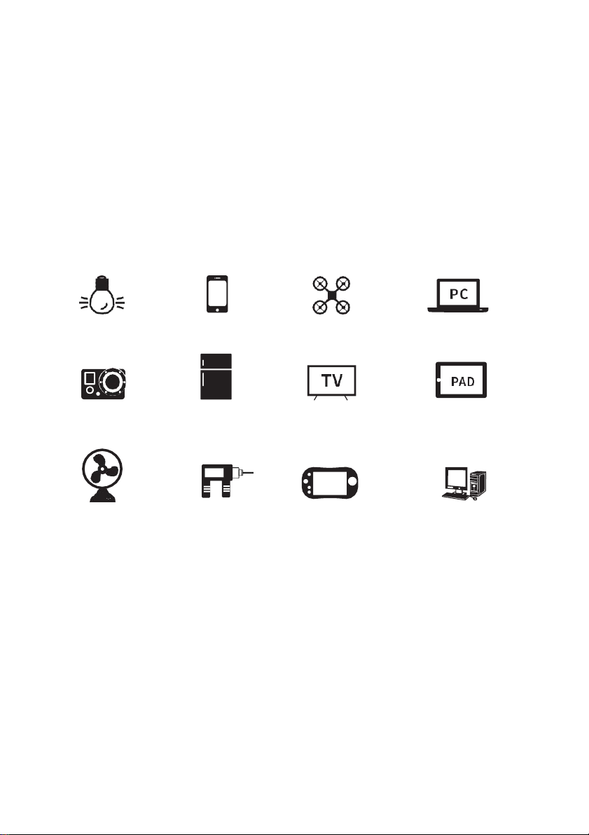
This product can charge or load below device, please choose corresponding product model for load power.
LED Light Cell Phone Drone Laptop Computer
Camera Refrigerator TV Set Tablet PC
Electric Fan Electric Drill Game player Desktop Computer
12
This manual suits for next models
1
Table of contents
Other Feider Machines Power Pack manuals


