Enerflow Eskom ERHP-SU14 User manual

Residential Heat Pump
User Manual
Please read this manual before operating the heat pump
July 2010
Page 2 of 13
www.mtechindustrial.com
CONFIDENTIAL
Proprietary Class 2
1. Cautions and Warnings
Caution: Installation and maintenance must only be performed by qualified personnel who
are familiar with local codes and regulations.
Warning: Ensure that the electricity/power supply is switched off before any installation
work begins. Note that electric shock is dangerous and can cause death.
Warning: Ensure that the electricity installation complies with local standards and
regulations. This appliance must be installed in accordance with the national wiring
regulations as contained in SANS 10142.
Warning: Do not turn off main power supply to the heat pump during a vacation or if not in
use. The heat pump must have electricity in order to protect itself during cold climate
conditions. It is recommended that the target temperature be set to 25 °C in order to save
electricity.
Warning: Do not turn the unit off and immediately on again. Allow 30 seconds for the
refrigerant pressure to equalize.
Caution: There are some sharp edges within the unit that may cause injury.
Caution: Note that the unit contains a rotating fan that may cause injury if the protective grid
is removed. Ensure not to touch or work on the unit while in operation.
Warning: This appliance is not intended for use by children or other individuals with reduced
physical, sensory or mental capabilities, or lack of experience and knowledge.

Page 3 of 13
www.mtechindustrial.com
CONFIDENTIAL
Proprietary Class 2
2. Heat Pump Controller Functions
2.1 Controller and Button Functions
The heat pump makes use of an intelligent controller and LCD display screen. The LCD screen is
used to change or view different operating parameters. The controller contains the following
interface and keyboard buttons:
Heating with Heat
Pump
Heating with Electric
Element
Water Tank
Temperature
Active Timer
Time

Page 4 of 13
www.mtechindustrial.com
CONFIDENTIAL
Proprietary Class 2
2.2 Heating Mode
Once the system is switched on at the main power, the intelligent controller will go into initialization
mode for a few seconds after which the time will be displayed as 00:00. The unit is now ready for
operation.
1
2
M
Press to turn on and
turn off the unit
Press to change
modes
Press to set operation parameter
during standby status, or check the
operation parameter under running or
standby status
Press to enter
timer setting
Note:
The user can select between two heating modes by simply pressing
1. Normal heating mode (heat pump only)
2. Fast heating mode (heat pump and electric element)
Warning: Do not turn off main power supply to the heat pump during a vacation or if
not in use. The heat pump must have electricity in order to protect itself during cold
climate conditions. It is recommended that the target temperature be set to 25 °C in
order to save electricity in periods of non use.
Page 5 of 13
www.mtechindustrial.com
CONFIDENTIAL
Proprietary Class 2
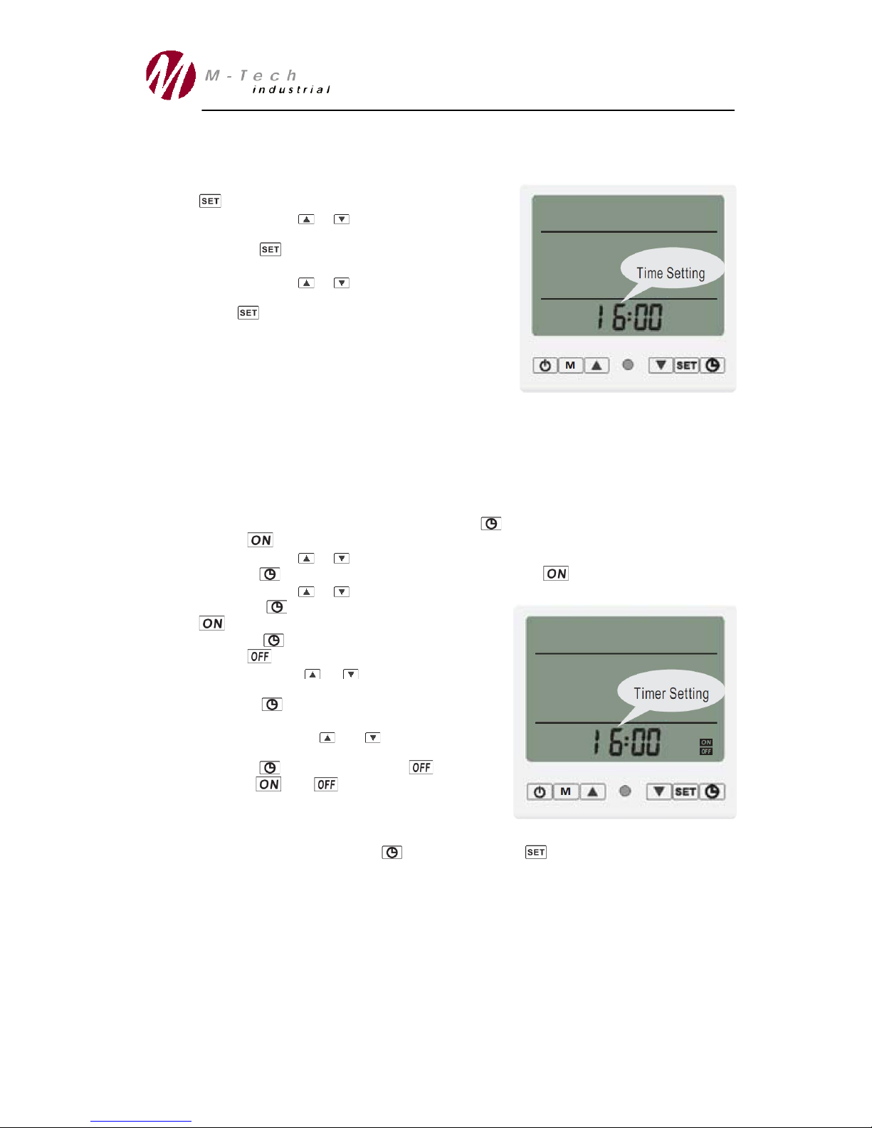
2.3 Time and timer function
In order to set/change the time, use the following procedure:
During the standby or running mode, press the
button once so that the Hour position flashes.
Make use of the or button to change the
Hour parameter.
Press the button so that the Minutes position
flickers.
Make use of the or button to change the
Minutes parameter.
Press to acknowledge the setting. Two beeps
will then sound to confirm the change.
Timer Function:
To select a period when the heat pump should not be in operation, such as during high electricity
demand in the household due to other appliances or during the night, the timer function can be
used to keep the heat pump switched off. In order to set the timer, use the following procedure:
During the standby or running mode, press the button twice so that the hour parameter
and the sign flashes.
Make use of the or button to set the Hour parameter.
Press the button so that the Minutes position and the sign flashes.
Make use of the or button to set the Minutes parameter.
Press the button to confirm the heat pump
time.
Press the button so that the Hour parameter
and the sign will flash.
Make use of the or button to set the Hour
parameter.
Press the button so that the Minutes position
flashes.
Make use of the or button to set the
Minutes parameter.
Press the button to confirm the time.
Both the and signs will be displayed on
the LCD screen, indicating that the timer function
is active.
Note:
To cancel the timer function, press the button and then the button.

Page 6 of 13
www.mtechindustrial.com
CONFIDENTIAL
Proprietary Class 2
2.4 Heat Pump Operating Parameters
Some of the heat pump control system operating parameters can be changed by the user if
required. The function and range of all the parameters are explained in the following table:
Parameter
Description
Range
Default
Remark
0
Return Water Temperature (Control Purposes)
12 °C
Factory Set
1
Target Water Temperature*
25 - 75 °C
40 °C
Adjustable
2
Defrosting Interval
30 - 90 min
40 min
Adjustable
3
Start Temperature for Defrosting Mode
-30 - 0 °C
-7 °C
Adjustable
4
Stop Temperature for Defrosting Mode
2 - 30 °C
13 °C
Adjustable
5
Defrosting Time
1 - 12 min
8 min
Adjustable
6
Installer function
-
10
-
7
Auto Restart Modes (Control Purposes)
-
1
Factory Set
8
Heating Mode (Control Purposes)
-
0
Factory Set
9
Micro Circulation Function (Off = 0; On = 1)
0 - 1
1
Adjustable
A
Set Temperature Difference - Difference
between water temperature and set temperature.
(The smaller the difference, the more frequently the
heat pump restarts)
1 - 5 °C
4
Adjustable
b
Excessive temperature difference between inlet and
outlet water. (Control Purposes)
13
Factory Set
c
Current Water Temperature in Tank
-9 ~ 90 °C
Output value
D
Water Outlet Temperature
-9 ~ 90 °C
Output value
E
Coil Temperature 1 (value for automatic control)
-9 ~ 90 °C
Output value
F
Coil Temperature 2
-9 ~ 90 °C
Output value
10
Ambient Temperature (value for automatic control)
-9 ~ 90 °C
Output value
* A maximum water temperature of 55°C can be reached by the heat pump alone. However, if the target temperature is set
between 55°C and 75°C the electric heater will be activated above 55°C to reach this temperature.
Remarks:
Parameter 1 –It is advised to set the target temperature at 55°C.
Parameter 2 –Interval between two defrosting operations. When ambient temperature is
lower, set this at a shorter interval for better performance.
Parameter 3 –The temperature setting at which the heat pump will start the defrosting
cycle. When ambient temperature is lower, set this temperature higher for complete defrost
of the heat pump evaporator.
Parameter 4 –The temperature setting where the defrost cycle is stopped. When ambient
temperature is lower, set this temperature higher for complete defrost of the heat pump
evaporator.
Parameter 5 –Defrosting time. When ambient temperature is lower, set this temperature
higher for complete defrost of the heat pump evaporator.
Page 7 of 13
www.mtechindustrial.com
CONFIDENTIAL
Proprietary Class 2
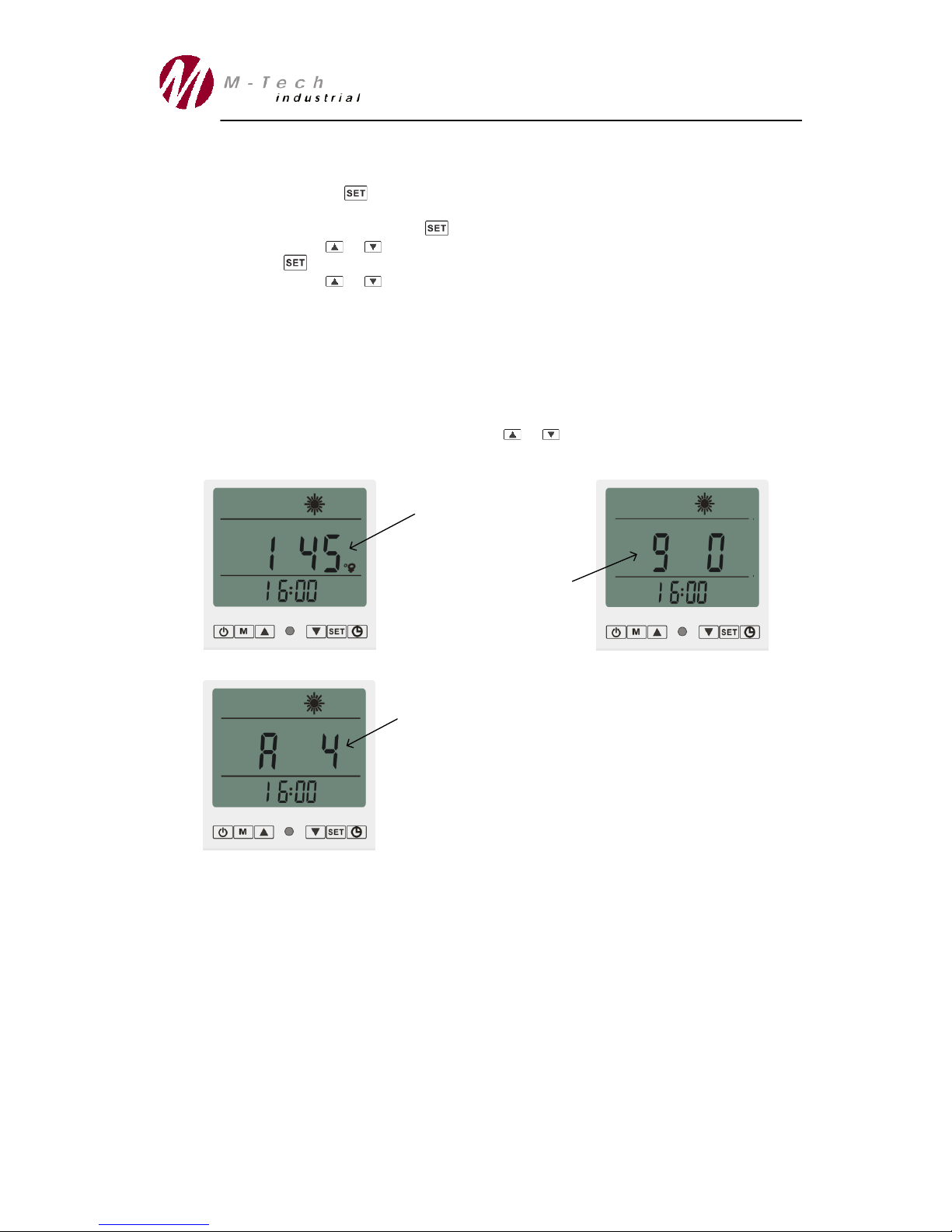
To access and change these parameters follow the steps below:
1. Press and hold the button for a few seconds when the unit is in standby mode (i.e. not
busy heating the water). Parameter 0 will flicker.
2. To change this value, press the button once.
3. Make use of the or button to change the value accordingly.
4. Press the button to confirm the setting.
5. Make use of the or button to select between the different operating parameters.
6. To change the values of these parameters, repeat steps 2 to 4.
7. Wait 5 seconds to exit this mode automatically.
Note:
The water temperature measured near the bottom of the water vessel is displayed on the
LCD screen continuously. The temperature displayed will drop as water is consumed and
cold water fills the vessel from the bottom.
If the target temperature needs to be changed, parameter 1 can be modified as explained
above or else the user can simply press the or button.
Target Water Temperature
Micro Circulation Function
0 = function off; 1 = function on
Temperature Difference between Target Temperature and
Measured Temperature before Heat Pump Start:
1°C = Heat Pump Starts More Frequently
5°C = Heat Pump Starts Less Frequently
Page 8 of 13
www.mtechindustrial.com
CONFIDENTIAL
Proprietary Class 2
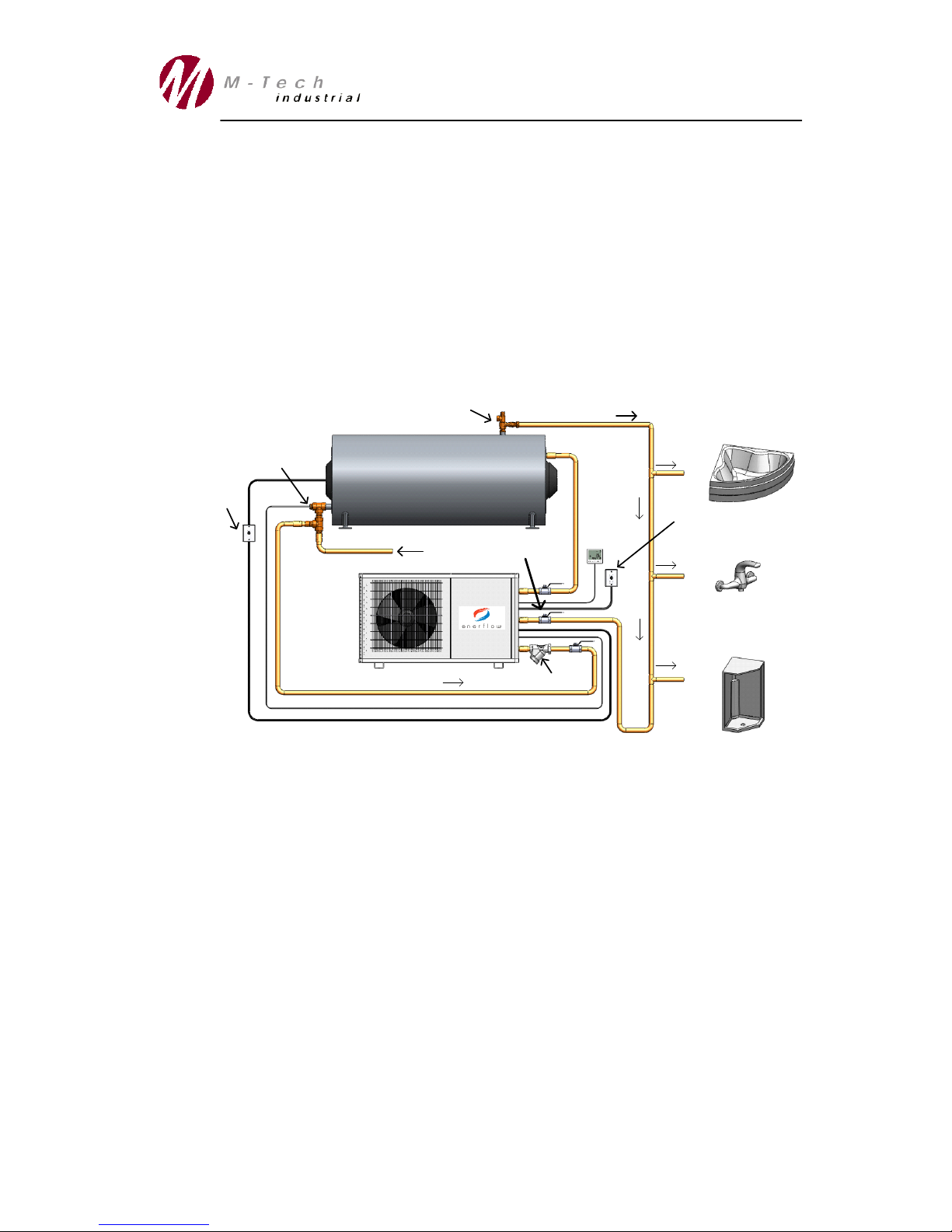
Micro Circulation function:
Note: All plumbing installations must comply with local standards and regulations. Refer to SANS
10254. The drawings below do not show additional components such as pressure control valves,
vacuum breakers and draincocks.
Your Enerflow heat pump has the functionality of heating a central, ring-main water distribution pipe
line. This function is used to ensure that hot water is supplied throughout the residence as an
instant hot-water-on-tap solution. The installer will ensure that the commissioning valve on the
return line is set on 10% bypass. Activate the micro circulation function by changing Parameter 9
to the value of 1 (as described in the previous section) on the intelligent controller. With this
function enabled, the water pump will run for 40 seconds during the period set in Parameter B
(adjustable between 1 and 60 minutes).
Hot Water Outlet
Safety Valve
Cold Water Inlet
Heat Pump
Temperature Probe
Main Power Supply
to Field Isolator
Field Isolator
Strainer
Flow direction
Commissioning Valve

Page 9 of 13
www.mtechindustrial.com
CONFIDENTIAL
Proprietary Class 2
3. Troubleshooting
Note: Please make use of the following table to do troubleshooting if an error or fault occurs. If the
problem persists shut down the system and switch off the main power supply and contact your
installer for assistance.
FAULT/ERROR
POSSIBLE CAUSES
CORRECTION/REMARK
Heat pump does not start
1. Main power supply off
2. Circuit breaker off
3. Heat pump protection imposed
(error message as below)
4. Loose electrical connections
5. Unit failure
1. Check power supply.
2. - Test for a electric leak/short-circuit
- Reset the circuit breakers
- Check that all electric components
have been installed correctly.
(Note: Do not work on electrical
components if you are not qualified.)
3. Identify the protection type and
correct the fault.
4. Check wiring connections and tighten
the terminal screws.
Fan does not work
1. No power supply
2. Fan motor fault
3. Loose connection
4. Obstruction
1. Check power supply.
2. Check if the fan rotates freely and
that no restrictions are present.
Replace if broken.
Heat pump works with
insufficient heating
1. Finned coil is dirty
2. Obstacle blocks air inlet/outlet
3. Insufficient refrigerant in heat
pump gas cycle
1. Clean the finned coil.
2. Remove the obstacle.
3. Add refrigerant (By Technician).
PP1
1. Water inlet temperature sensor
failure
1. Contact installer to check
connections and replace sensor if
required.
PP2
1. Discharge gas temperature sensor
failure
1. Contact installer to check
connections and replace sensor if
required.
.PP3
1. Coil temperature failure
1. Contact installer to check
connections and replace sensor if
required.
PP5
1. Room temperature failure
1. Contact installer to check
connections and replace sensor if
required.
PP6
1. Electricity leakage protection
1. Switch off main power supply to the
heat pump, wait 30 seconds and switch
on again. If the problem persists, please
contact your installer.
PP7
1. Anti-frosting protection in winter
1. Ambient temperature too low .

Page 10 of 13
www.mtechindustrial.com
CONFIDENTIAL
Proprietary Class 2
EE1
1. High or Low pressure protection
2. Possible airlock in the water pump
3. Insufficient water supply
1. Switch off main power supply to the
heat pump, wait 30 seconds and switch
on again. If the problem persists, please
contact your installer.
2. Clean strainer and open a hot water
tap to flush/prime the water lines
3. Ensure that the fan is not restricted
by dirt or leafs.
4. Check main water supply pressure
EE2
1. Over current protection
1. Switch off main power supply to the
heat pump, wait 30 seconds and switch
on again. If the problem persists, please
contact your local installer.
EE3
1. Water switch failure
1. Switch off main power supply to the
heat pump, wait 30 seconds and switch
on again. If the problem persists, please
contact your local installer.
EE8
1. Communication failure
1. Reconnect LCD display unit.
2. Switch off main power supply to the
heat pump, wait 30 seconds and switch
on again. If the problem persists, please
contact your local installer.
Defrosting Sign Indicating
1. Defrosting failure
1. Defrosting sign will show
permanently on LCD screen.
2. Switch off main power supply to the
heat pump, wait 30 seconds and switch
on again. If the problem persists, please
contact your local installer.
Please note the following:
1. Outdoor temperature, water inlet temperature and parameter settings may affect the
performance and power consumption of the heat pump unit.
2. Make sure that the heat pump air duct is not blocked
3. If the ambient temperature is too high, the fan may stop in order to protect the system. The
heat pump will however still provide hot water to the geyser tank. If the temperature
decreases the fan will restart again.
4. If the unit goes into the defrosting mode the fan may stop. Once the coil temperature is
high enough the fan will restart.
5. Make sure that the unit is well ventilated and that no cold air is redirected back into the
evaporator (i.e. do not install the heat pump in small enclosed room where it may re-
circulate the cold air given of).
6. Make sure that all the isolation valves are open before the heat pump is started

Page 11 of 13
www.mtechindustrial.com
CONFIDENTIAL
Proprietary Class 2
4. Service and Maintenance
Service and maintenance operations should be carried out by
qualified personnel who are well trained within the refrigeration
engineering field.
Although your Enerflow heat pump is a self contained and reliable means
of providing eco-friendly hot water, some maintenance and service
needs to be performed. The following items should be checked:
The airway of the fan and the evaporator needs to be cleaned six monthly to ensure effective
airflow and heat transfer. Remove items such as cobwebs, leafs and the like. Do not use a
high pressure water hose to spray down the unit, the heat exchanger fins may be damaged.
The strainer should be checked regularly, especially two days after initial installation. This is
done by removing the bonnet of the strainer with a spanner and removing the strainer element
(sieve). The strainer element can be flushed under running water before reinserting it and
closing the bonnet again.
Bonnet
Strainer Element
Ensure that the water supply is sufficient at all times.
No maintenance needs to be performed on the internal components of your Enerflow heat
pump.
The unit is designed with a close loop gas cycle that does not need short term maintenance or
service under normal operation.
Ensure that the system is drained completely of water if it is not going to be used in the winter
in order to avoid a pipe burst/damage due to freezing.

Page 12 of 13
www.mtechindustrial.com
CONFIDENTIAL
Proprietary Class 2
5. Performance Specifications
Unit may be improved or technical data may be modified without prior notice. For
specific technical parameters, please check the plate on the side of the unit.
5.1 Model ERHP-SU14
ITEM
UNIT
VALUE
Model range
ERHP-SU14
Refrigerant
R407C
Mass of Refrigerant
g
1100
Power Supply –Voltage
V
230/1ph
Power Supply –Frequency
Hz
50
Heat Pump Rated Current
A
6.2
Heat Pump Rated Power Supply
kW
1.4
Coefficient of Performance (COP)
W/W
3.5 *
Electric Heater Rated Current
A
9
Electric Heater Rated Power Output
kW
2 **
Water Temperature Setting Range
°C
30 ~ 55 ~ 75 ***
Maximum Water Temperature
°C
75
Highest Ambient Temperature
°C
43
Lowest Ambient Temperature
°C
-5
Water Tank Allowable
L
100 –500
Maximum Water Pressure
MPa
0.7
Discharge Pressure
MPa
2.8
Suction Pressure
MPa
0.5
Inlet and Outlet Water Pipe Diameter
Inch
1/2"
Protection against water class
IPX4
Noise Level
dBA
60 ***
Net Weight
kg
65
Net Dimension
w x d x h
953 x 360 x 555
Packing Dimension
w x d x h
1013 x 380 x 575
Note:
* Testing condition: Ambient Temperature DB 20°C / WB15°C.
Water outlet temperature 55°C.
** Size the electric heater by considering the volume of the water tank.
*** Water temperature can reach 55°C by the heat pump alone. However if the water
temperature needs to reach 75°C the electric heater will be activated.
*** Noise level was tested in ARI Standard Acoustic Room.

Page 13 of 13
www.mtechindustrial.com
CONFIDENTIAL
Proprietary Class 2
6. Installation Handover
Once the installation is complete and the system tested, make sure that the
client understands the operation and safety requirements of the heat pump.
All repair and service work that needs to be performed to this product must be
done by a qualified person.
Ensure that the details of the certificate below are completed by both the client
and the installer to ensure the warranty on the heat pump unit is valid.
Please keep this certificate safe for warranty purposes.
Residential Heat Pump - Installation Certificate
Date: Heat Pump Serial Number:
Installer Detail
Company Name: Reference Number:
Surname: Name:
Tel:
Signature:
Client Details
Surname: Name:
Address:
Suburb:
City:
Tel:
I (the undersigned) acknowledge that the installation was completed and tested. I confirm
that the installer has shown me the workings and operation of my Enerflow heat pump. I
also understand the operation and safety requirements for this heat pump unit.
Signature:
Table of contents
Other Enerflow Heat Pump manuals


Popular Heat Pump manuals by other brands


REMKO
REMKO WKF Series Electrical Wiring Manual

Nibe
Nibe S1155 Installer manual
 Service manual")
Gree
Gree GUD24W2/D-D(U) Service manual

STIEBEL ELTRON
STIEBEL ELTRON WPL 33 HT S Operation and installation

Johnson Controls Unitary Products
Johnson Controls Unitary Products BHZ024-060 installation manual

Mitsubishi Electric
Mitsubishi Electric PUZ-HWM140HA Series installation manual

Ariston
Ariston NIMBUS M NET user manual

Heat Controller
Heat Controller VMH C Series Service manual

Regulus
Regulus CSE2 MIX F W 1F Installation and operation manual

Rheem
Rheem RKNA SERIES installation instructions

GeoSmart
GeoSmart ECO-Y installation manual

Carrier
Carrier 38AH044 38AH044-134 Installation and service instructions