Installation methods
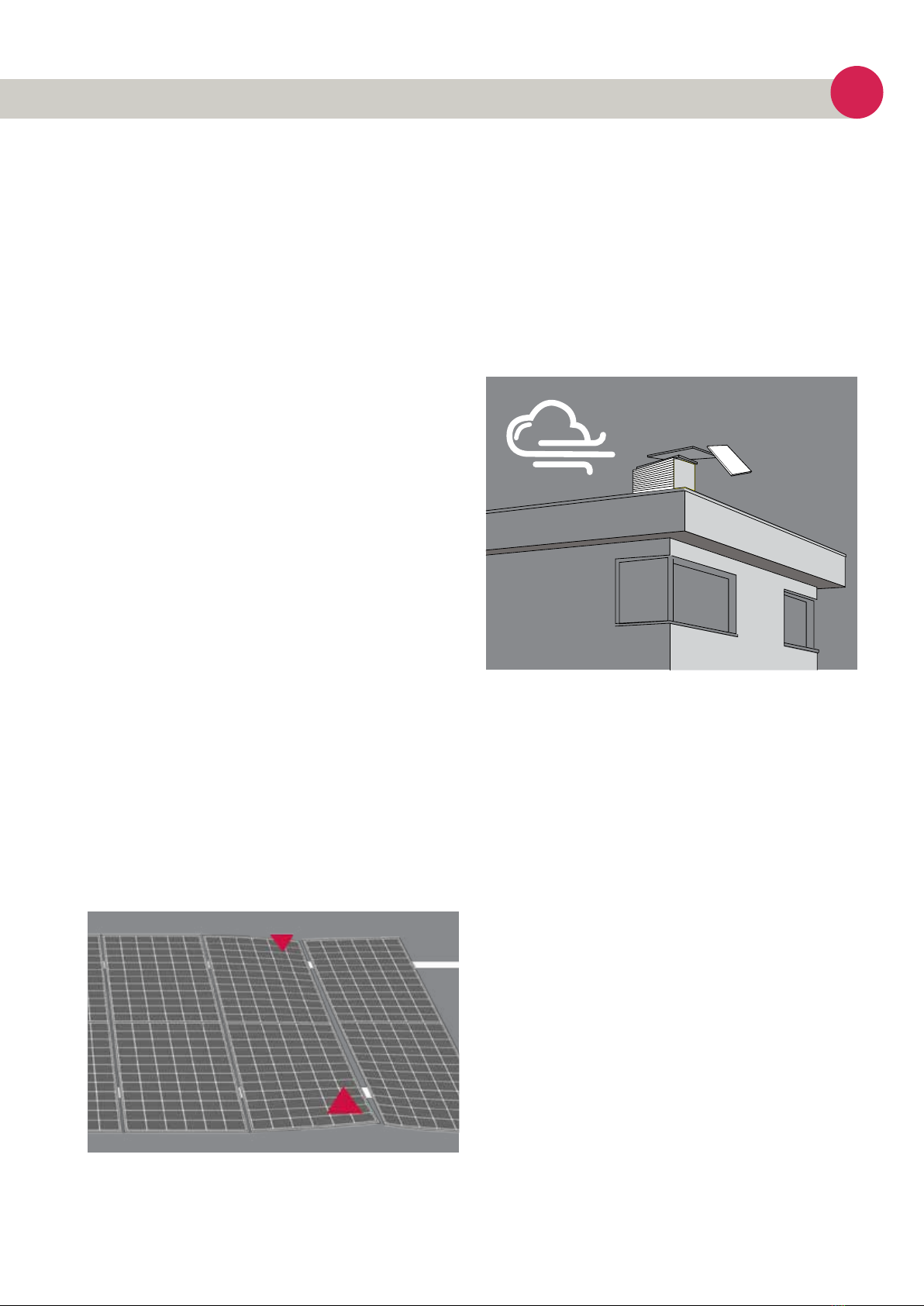
Free from shading
Optimal solar radiation leads to maximum energy yields:
» Set up modules so that they face the sun.
» Avoid shading (e.g. from buildings, chimneys, trees).
» Avoid partial shading (e.g. from overhead lines, dirt,
snow).
» Energetica solar modules can be used up to an altitude of
4000 m.
INSTALLATION METHODS
General information
» To maximize sun exposure, choose an appropriate orien
tation.
» The module must be stored so that the glass faces up.
At the same time, a suitable, water-repellent cover on the
back prevents moisture from penetrating the connector
and creating a security risk.
» To avoid damage, never drop objects on the modules.
Also, never step on the modules, do not subject them
to mechanical stress or deform them through mechanical
stress.
» A suitable distance must be maintained between the
frame of the solar modules and the respective under-
ground, such as roof or floor, in order to avoid damage to
the cabling and to allow air to circulate behind the solar
module. The recommended minimum distance is 100mm.
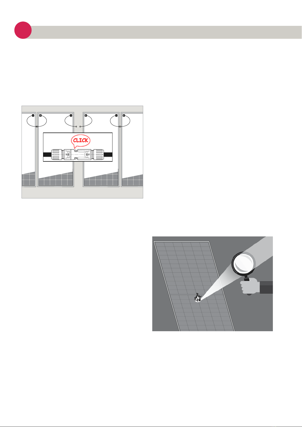
» Modules must never be mounted upside down. Cables
and plugs must always point downwards.
» When installing PV modules in snowy areas, Energetica
Industries recommends taking appropriate measures to
prevent damage to the backside of the frame from sliding
snow. We recommend using corrosion-resistant materials
for such additional structures.
» Each module should be securely fastened at at least four
points on two opposite sides.
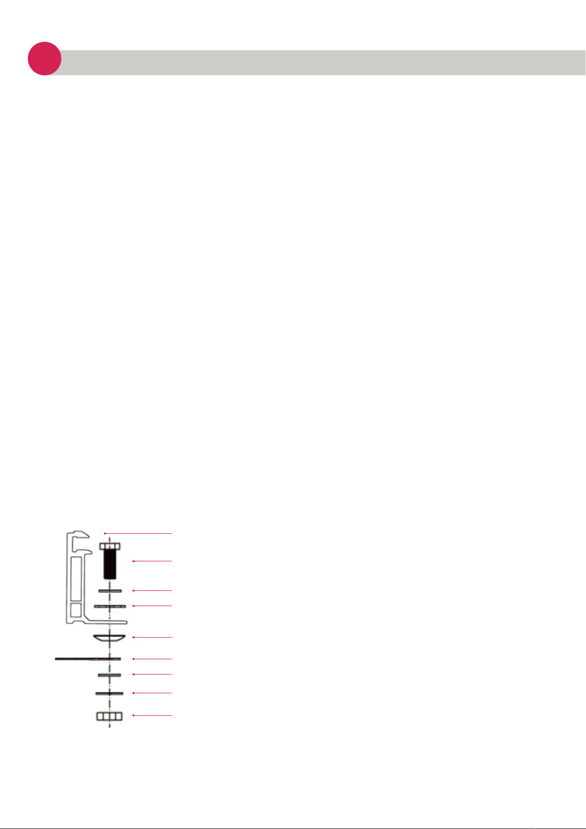
» Only use corrosion-resistant parts as installation rails and
fastening material. Use suitable screw or clamp con-
nections as required in the manufacturer's instructions.
» After installation, there must be no electrical parts (such
as cables) between the laminate and the substructure.
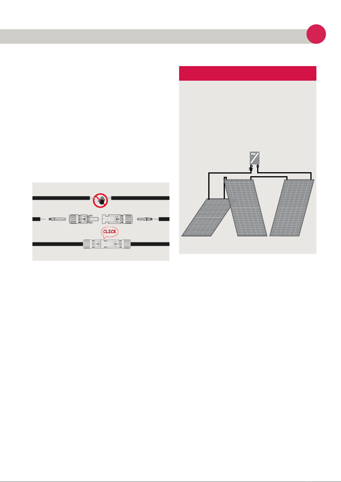
» Make sure that the plug connections are never in the
water.
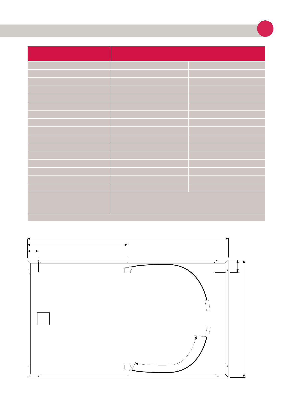
» Detailed information on the dimensions of the solar
modules and the position of the installation holes can be
found in the “Product Specifications” section.
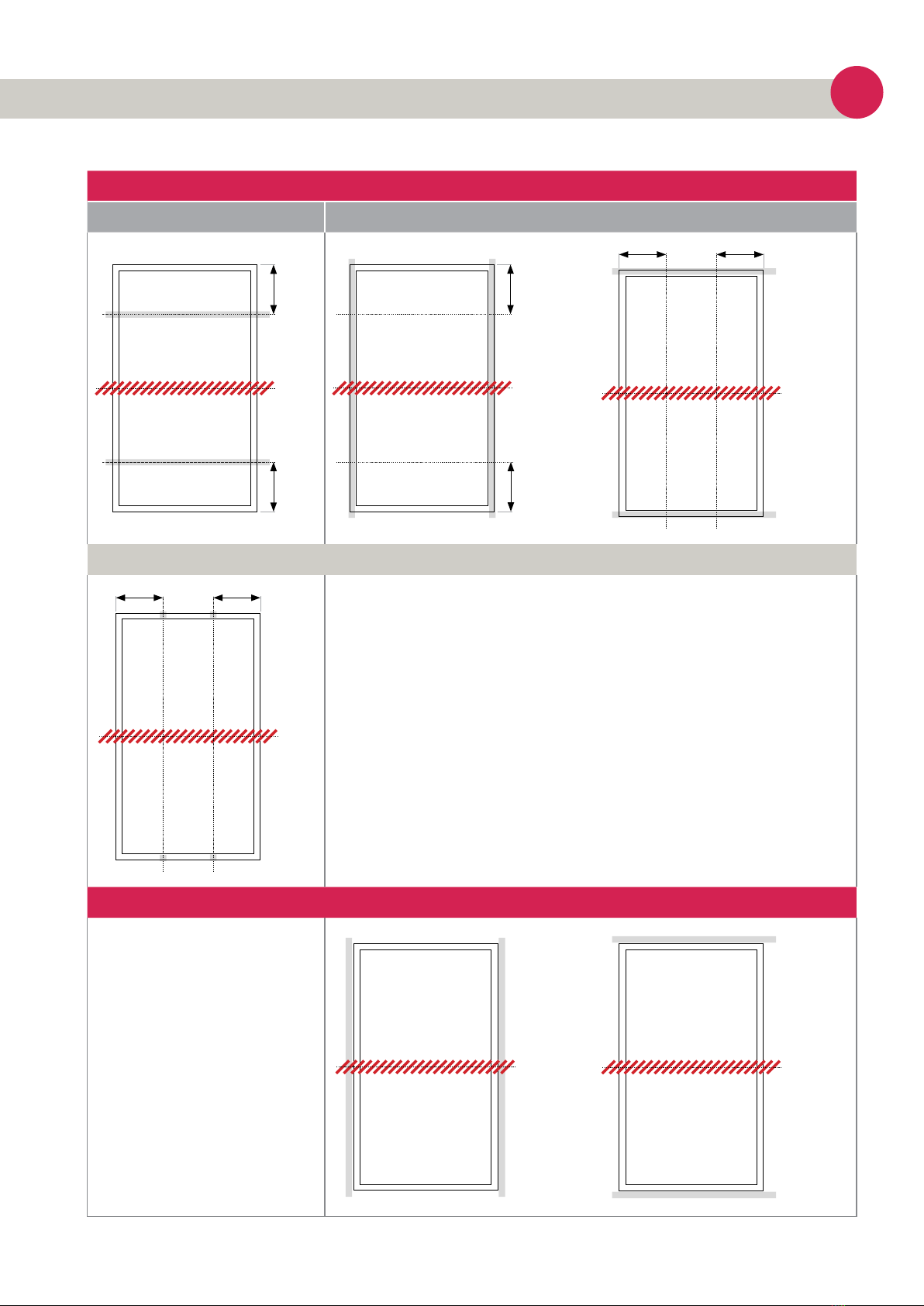
Installation with clamps
» The module can be attached to the substructure on both
the long and the short edge using clamps.
» You can find detailed information about the positioning
of the clamps in the installation options on page 11.
» If you use a special clamp, it must be tested for
compatibility by Energetica Industries.
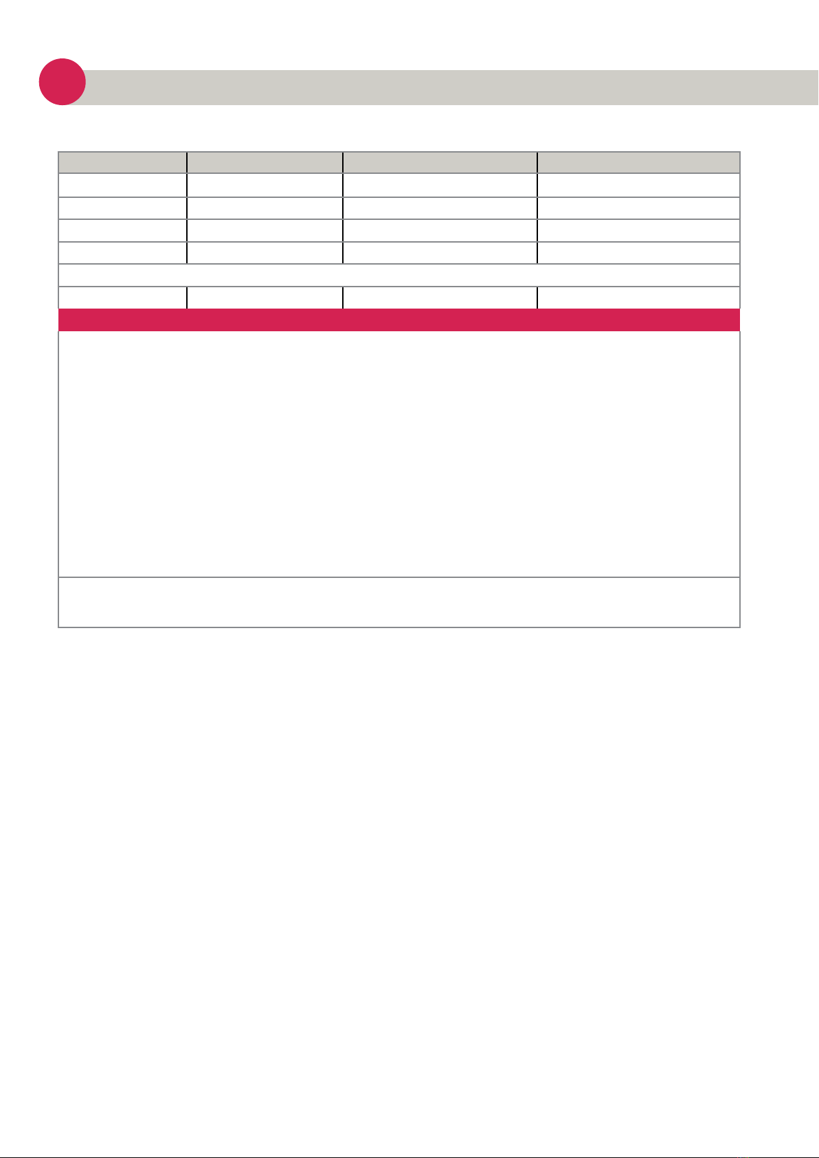
Planning
Check whether the maximum snow loads of the modules
are suitable for the relevant snow load zone. For zones with
a correspondingly high snow load, we recommend our
e.Prime series with higher mechanical stability.
» Adding additional installation holes can damage the solar
module and affect the stability of the frame.
» We recommend leaving a gap of 10 mm between the
module frames in order to prevent tension due to
thermal expansion.
Disclaimer of liability
» The installer must read and fully understand this
installation manual before beginning the installation
process.
» If you have any questions about the manual or any
concerns, the installer should contact Energetica
Industries and express them.
Recycling
Do not decommission module yourself, but hire a specialist
company. Dispose of the modules in accordance with the
local disposal regulations.
The original foil of the pallet packaging from Energetica
Industries consists of biodegradable and recyclable plastic
and was made from renewable raw materials (corn starch).
Please dispose of the packaging in accordance with the
country-specific disposal regulations.
Page 9
e