ENERGOPOMIAR ELEKTRYKA TKP-1 Parts list manual

VACUUM CHAMBERS TESTING DEVICE
Type TKP-1
TECHNICAL DESCRIPTION AND OPERATION MANUAL
And I don't
have one yet
I'm happy
because I have a
perfect Polish
product.

VACUUM CHAMBERS TESTING DEVICE TKP-1 Type Page 2
MANUFACTURER: Zakład Pomiarowo-Badawczy Energetyki
ENERGOPOMIAR-ELEKTRYKA Spółka z o.o.
ADDRESS: ul. Świętokrzyska 2
44-101 Gliwice
Postbox 71"A"
PHONE: Head Quarters (32) 237-66-15
FAX: (32) 231-08-70
PRODUCTION: Tel. (32) 237-66-70
INTERNET: www.elektryka.com.pl
E-MAIL: [email protected]
Chief Inspectorate for Environmental Protection: E0022500W
Energopomiar-Elektryka sp. z o.o. reserves the right to make changes to its products in order to
improve their technical features. The changes may not always be included in the documentation as they
appear.
Brand and product names in this operation manual are trademarks or registered trademarks that
belong to their respective owners.
This product consists of different materials –some of them are recyclable, others require disposal –
which means you need to obtain information on the recycling or disposal systems for this kind of
products in your local regulations, or return the product to the seller/manufacturer.
Note: Some parts of this device may contain substances that are contaminating or hazardous for the
environment. It is not allowed to dispose of this product along with other domestic waste (as shown by
the symbol below), as it may cause major harm to the environment and human health.
It is required to perform a "selective collection" for the purpose of disposal as specified in the Act
as of 11/Sept/2015 on Used Electrical and Electronic Equipment ( Polish Journal of Laws Dz.U.z 2015r,
poz. 1688).
This document may be copied and disseminated only as a whole.
Copying some part of it is possible only with the written consent of Energopomiar - Elektryka sp. z o.o.

VACUUM CHAMBERS TESTING DEVICE TKP-1 Type Page 3
CONTENTS
1
1.
. P
PR
RO
OD
DU
UC
CT
T
U
US
SE
E
.
..
..
..
..
..
..
..
..
..
..
..
..
..
..
..
..
..
..
..
..
..
..
..
..
..
..
..
..
..
..
..
..
..
..
..
..
..
..
..
..
..
..
..
..
..
..
..
..
..
..
..
..
..
..
..
..
..
..
..
..
..
..
..
..
..
..
..
..
..
..
..
..
..
..
..
..
..
..
..
..
..
..
..
..
..
..
..
..
..
..
..
..
..
..
..
..
..
..
..
..
..
..
..
..
..
..
..
..
..
..
..
..
..
..
..
..
..
..
..
..
..
..
..
..
..
..
..
.
4
4
2
2.
. T
TE
EC
CH
HN
NI
IC
CA
AL
L
D
DA
AT
TA
A
.
..
..
..
..
..
..
..
..
..
..
..
..
..
..
..
..
..
..
..
..
..
..
..
..
..
..
..
..
..
..
..
..
..
..
..
..
..
..
..
..
..
..
..
..
..
..
..
..
..
..
..
..
..
..
..
..
..
..
..
..
..
..
..
..
..
..
..
..
..
..
..
..
..
..
..
..
..
..
..
..
..
..
..
..
..
..
..
..
..
..
..
..
..
..
..
..
..
..
..
..
..
..
..
..
..
..
..
..
..
..
..
..
..
..
..
..
..
..
..
..
..
..
.
4
4
3
3.
. S
ST
TR
RU
UC
CT
TU
UR
RA
AL
L
D
DE
ES
SC
CR
RI
IP
PT
TI
IO
ON
N
.
..
..
..
..
..
..
..
..
..
..
..
..
..
..
..
..
..
..
..
..
..
..
..
..
..
..
..
..
..
..
..
..
..
..
..
..
..
..
..
..
..
..
..
..
..
..
..
..
..
..
..
..
..
..
..
..
..
..
..
..
..
..
..
..
..
..
..
..
..
..
..
..
..
..
..
..
..
..
..
..
..
..
..
..
..
..
..
..
..
..
..
..
..
..
..
..
..
..
..
..
..
..
..
..
..
..
.
5
5
P
Po
ow
we
er
r
s
su
up
pp
pl
ly
y
.
..
..
..
..
..
..
..
..
..
..
..
..
..
..
..
..
..
..
..
..
..
..
..
..
..
..
..
..
..
..
..
..
..
..
..
..
..
..
..
..
..
..
..
..
..
..
..
..
..
..
..
..
..
..
..
..
..
..
..
..
..
..
..
..
..
..
..
..
..
..
..
..
..
..
..
..
..
..
..
..
..
..
..
..
..
..
..
..
..
..
..
..
..
..
..
..
..
..
..
..
..
..
..
..
..
..
..
..
..
..
..
..
..
..
..
..
..
..
.
5
5
O
Ou
ut
tp
pu
ut
t
c
ci
ir
rc
cu
ui
it
t
.
..
..
..
..
..
..
..
..
..
..
..
..
..
..
..
..
..
..
..
..
..
..
..
..
..
..
..
..
..
..
..
..
..
..
..
..
..
..
..
..
..
..
..
..
..
..
..
..
..
..
..
..
..
..
..
..
..
..
..
..
..
..
..
..
..
..
..
..
..
..
..
..
..
..
..
..
..
..
..
..
..
..
..
..
..
..
..
..
..
..
..
..
..
..
..
..
..
..
..
..
..
..
..
..
..
..
..
..
..
..
..
..
..
..
..
..
..
..
.
6
6
C
Co
on
nt
tr
ro
ol
l
k
ke
ey
yb
bo
oa
ar
rd
d
.
..
..
..
..
..
..
..
..
..
..
..
..
..
..
..
..
..
..
..
..
..
..
..
..
..
..
..
..
..
..
..
..
..
..
..
..
..
..
..
..
..
..
..
..
..
..
..
..
..
..
..
..
..
..
..
..
..
..
..
..
..
..
..
..
..
..
..
..
..
..
..
..
..
..
..
..
..
..
..
..
..
..
..
..
..
..
..
..
..
..
..
..
..
..
..
..
..
..
..
..
..
..
..
..
..
..
..
..
..
..
..
..
.
6
6
C
Co
on
nt
tr
ro
ol
l
b
bu
ut
tt
to
on
ns
s
a
an
nd
d
c
co
on
nt
tr
ro
ol
l
l
li
ig
gh
ht
ts
s
.
..
..
..
..
..
..
..
..
..
..
..
..
..
..
..
..
..
..
..
..
..
..
..
..
..
..
..
..
..
..
..
..
..
..
..
..
..
..
..
..
..
..
..
..
..
..
..
..
..
..
..
..
..
..
..
..
..
..
..
..
..
..
..
..
..
..
..
..
..
..
..
..
..
..
..
..
..
..
..
..
..
..
..
..
..
.
6
6
M
ME
EN
NU
U
o
op
pt
ti
io
on
ns
s.
..
..
..
..
..
..
..
..
..
..
..
..
..
..
..
..
..
..
..
..
..
..
..
..
..
..
..
..
..
..
..
..
..
..
..
..
..
..
..
..
..
..
..
..
..
..
..
..
..
..
..
..
..
..
..
..
..
..
..
..
..
..
..
..
..
..
..
..
..
..
..
..
..
..
..
..
..
..
..
..
..
..
..
..
..
..
..
..
..
..
..
..
..
..
..
..
..
..
..
..
..
..
..
..
..
..
..
..
..
..
..
..
..
..
..
..
..
.
7
7
4
4.
. T
TE
ES
ST
TE
ER
R
O
OP
PE
ER
RA
AT
TI
IO
ON
N
.
..
..
..
..
..
..
..
..
..
..
..
..
..
..
..
..
..
..
..
..
..
..
..
..
..
..
..
..
..
..
..
..
..
..
..
..
..
..
..
..
..
..
..
..
..
..
..
..
..
..
..
..
..
..
..
..
..
..
..
..
..
..
..
..
..
..
..
..
..
..
..
..
..
..
..
..
..
..
..
..
..
..
..
..
..
..
..
..
..
..
..
..
..
..
..
..
..
..
..
..
..
..
..
..
..
..
..
..
..
..
..
..
..
..
..
..
..
..
.
7
7
5
5.
. T
TK
KP
P-
-1
1
T
TE
ES
ST
TE
ER
R
S
SA
AF
FE
E
O
OP
PE
ER
RA
AT
TI
IN
NG
G
C
CO
ON
ND
DI
IT
TI
IO
ON
NS
S
.
..
..
..
..
..
..
..
..
..
..
..
..
..
..
..
..
..
..
..
..
..
..
..
..
..
..
..
..
..
..
..
..
..
..
..
..
..
..
..
..
..
..
..
..
..
..
..
..
..
..
..
..
..
..
..
..
..
..
..
..
..
..
..
..
..
..
..
..
..
..
..
..
..
..
..
..
..
.
9
9
C
CH
HE
EC
CK
K
L
LI
IS
ST
T
.
..
..
..
..
..
..
..
..
..
..
..
..
..
..
..
..
..
..
..
..
..
..
..
..
..
..
..
..
..
..
..
..
..
..
..
..
..
..
..
..
..
..
..
..
..
..
..
..
..
..
..
..
..
..
..
..
..
..
..
..
..
..
..
..
..
..
..
..
..
..
..
..
..
..
..
..
..
..
..
..
..
..
..
..
..
..
..
..
..
..
..
..
..
..
..
..
..
..
..
..
..
..
..
..
..
..
..
..
..
..
..
..
..
..
..
..
..
..
..
..
..
..
..
..
..
..
..
..
..
..
..
..
..
..
..
..
..
.
1
10
0
W
WA
AR
RR
RA
AN
NT
TY
Y
C
CA
AR
RD
D
.
..
..
..
..
..
..
..
..
..
..
..
..
..
..
..
..
..
..
..
..
..
..
..
..
..
..
..
..
..
..
..
..
..
..
..
..
..
..
..
..
..
..
..
..
..
..
..
..
..
..
..
..
..
..
..
..
..
..
..
..
..
..
..
..
..
..
..
..
..
..
..
..
..
..
..
..
..
..
..
..
..
..
..
..
..
..
..
..
..
..
..
..
..
..
..
..
..
..
..
..
..
..
..
..
..
..
..
..
..
..
..
..
..
..
..
..
..
..
..
..
..
..
..
..
..
..
.
1
11
1

VACUUM CHAMBERS TESTING DEVICE TKP-1 Type Page 4
1. PRODUCT USE
TKP-1 Vacuum Chambers Tester is a portable microprocessor device used for testing
vacuum chambers of switches. The testing involves the analysis of leakage current rate as the DC
voltage is generated.
2. TECHNICAL DATA
Rated voltage of device power supply: 230V , 50Hz
Max. power consumption: approx. 400VA
Adjustment range of output voltage: (10 ÷ 80)kV DC (every 1kV)
Detection current: (0.1 ÷ 0.5)mA
Permissible basic error of voltage measurement: ± 1kV
Permissible basic error of current measurement: ± 2A
Operating temperature: -5C ÷ +40C
Humidity: up to 80 %
Dimensions: 486392192mm
Mass: approx. 12kg
VACUUM CHAMBERS TESTING DEVICE TKP-1 Type Page 5
3. STRUCTURAL DESCRIPTION
Vacuum Chambers Tester Type TKP-1 is placed in the suitcase made of a highly mechanical
resistant material.
Power supply
This device is supplied from 230V, 50Hz zero-phase network. Internal, measuring and control
circuits are secured with a 2A fuse. The device is powered up using the power supply switch on the
side edge. In emergency, use the safety switch to power down and stop the operation of the
device. The switch is released by rotating the dial clockwise.
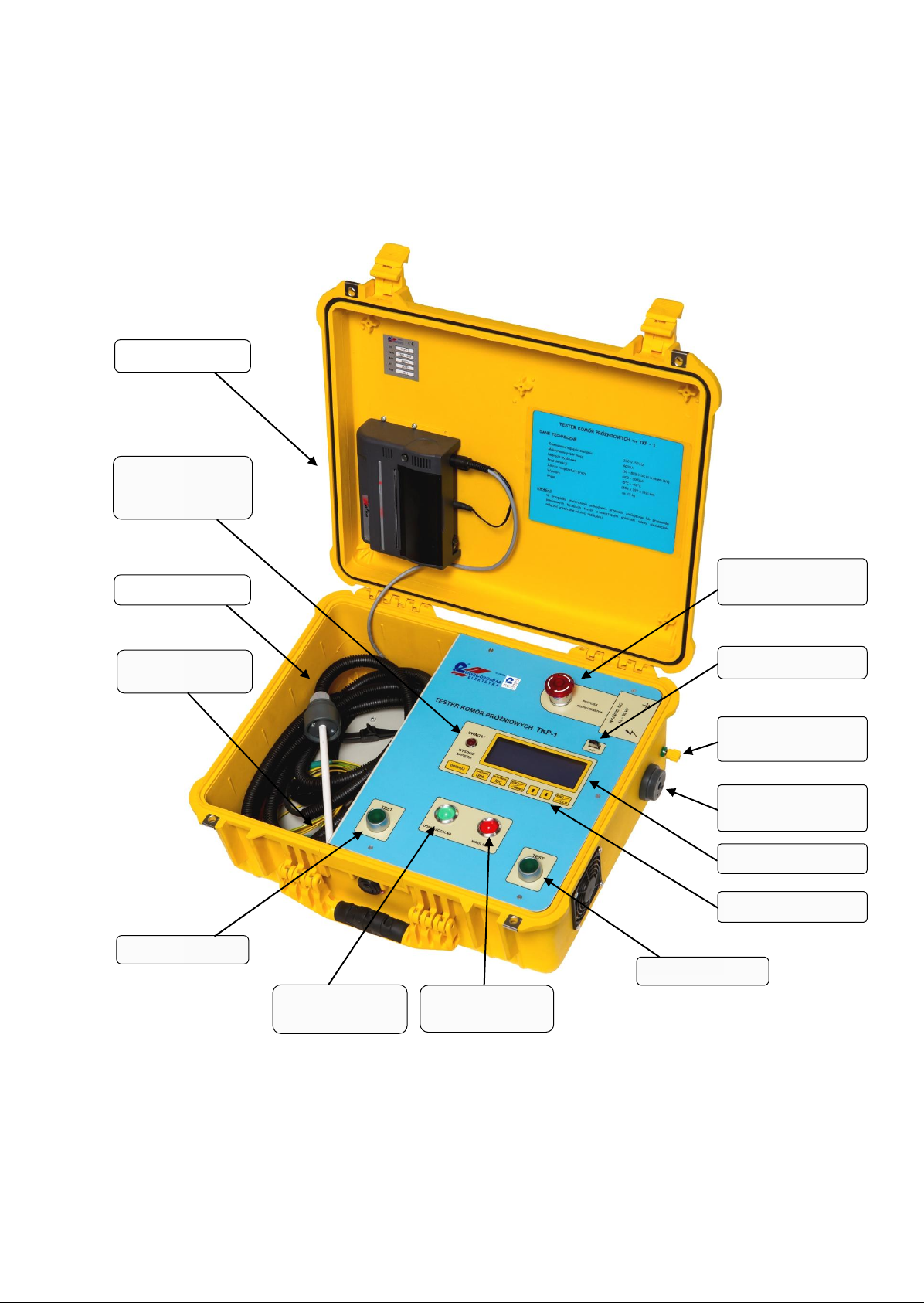
W
Wa
ar
rn
ni
in
ng
g
L
LE
ED
D
A
AT
TT
TE
EN
NT
TI
IO
ON
N
!
!
H
HI
IG
GH
H
V
VO
OL
LT
TA
AG
GE
E
H
HV
V
c
ca
ab
bl
le
e
c
co
on
nn
ne
ec
ct
ti
io
on
n
s
so
oc
ck
ke
et
t
T
TE
ES
ST
T
b
bu
ut
tt
to
on
n
D
De
ev
vi
ic
ce
e
p
po
ow
we
er
r
s
su
up
pp
pl
ly
y
s
sw
wi
it
tc
ch
h
R
Re
ed
d
c
co
on
nt
tr
ro
ol
l
l
li
ig
gh
ht
t
L
LC
CD
D
d
di
is
sp
pl
la
ay
y
G
Gr
re
ee
en
n
c
co
on
nt
tr
ro
ol
l
l
li
ig
gh
ht
t
T
Th
he
er
rm
ma
al
l
p
pr
ri
in
nt
te
er
r
C
Co
on
nt
tr
ro
ol
l
k
ke
ey
yb
bo
oa
ar
rd
d
H
HV
V
c
ca
ab
bl
le
e
S
Sa
af
fe
et
ty
y
e
em
me
er
rg
ge
en
nc
cy
y
s
sw
wi
it
tc
ch
h
G
Gr
ro
ou
un
nd
di
in
ng
g
c
cl
la
am
mp
p
–
–
s
se
ec
co
on
nd
d
D
DC
C
v
vo
ol
lt
ta
ag
ge
e
p
po
ol
le
e
T
TE
ES
ST
T
b
bu
ut
tt
to
on
n
U
US
SB
B
s
so
oc
ck
ke
et
t

VACUUM CHAMBERS TESTING DEVICE TKP-1 Type Page 6
Output circuit
The device enables generation of the DC voltage adjustable between 10kV and 80kV with a
step every 1kV. This output features the detection of exceeded adjustable threshold of load current
within the range (0.1 ÷ 0.5)mA with a step every 0.01mA. When this threshold is exceeded, the
output voltage drops and the corresponding control light is lit.
To connect the HV cable and the neutral wire that come as a standard equipment of the
device, use the socket and clamp on the right side of casing.
Control keyboard
Button functions are as follows:
–to enter the MENU or confirm your selection,
–to leave the MENU or cancel your choice and to clear the red light
DEFECTIVE WADLIWA,
–to navigate through the MENU or change the value while setting
the date and time,
–to navigate the cursor to the left while setting the date and time,
–to navigate the cursor to the right while setting the date and time,
–to decrease the set output voltage,
–to increase the set output voltage,
–to decrease the set current detection,
–to increase the set current detection,
–to print the current memory record,
The buttons are active only when a test with the generation of output DC voltage is
currently not running.
Control buttons and control lights
To switch on the DC output voltage use the two green monostable buttons described as
TEST . The generation of output voltage is possible only when both buttons are pressed at the same
time. To switch on the output circuit the TKP-1 cannot be in the process of setting output
parameters or viewing the MENU.
E
EN
NT
T
M
ME
EN
NU
U
D
DR
RU
UK
KU
UJ
J
P
PR
RI
IN
NT
T
N
NA
AS
ST
TA
AW
WA
A
U
UD
DC
C
S
SE
ET
TT
TI
IN
NG
G
N
NA
AS
ST
TA
AW
WA
A
I
ID
DC
C
S
SE
ET
TT
TI
IN
NG
G
+
+
N
NA
AS
ST
TA
AW
WA
A
U
UD
DC
C
S
SE
ET
TT
TI
IN
NG
G
+
+
,
,
N
NA
AS
ST
TA
AW
WA
A
I
ID
DC
C
S
SE
ET
TT
TI
IN
NG
G
+
+
+
+
E
ES
SC
C
C
CL
LR
R
N
NA
AS
ST
TA
AW
WA
A
U
UD
DC
C
S
SE
ET
TT
TI
IN
NG
G
N
NA
AS
ST
TA
AW
WA
A
I
ID
DC
C
S
SE
ET
TT
TI
IN
NG
G

VACUUM CHAMBERS TESTING DEVICE TKP-1 Type Page 7
When the output DC voltage is switched on the LED ATTENTION UWAGA!f
fl
la
as
sh
he
es
sHIGH
VOLTAGE WYSOKIE NAPIĘCIE .
Once the test is finished and while viewing the memory records using the red or green
control light, the test result is shown. If the load current does not exceed the set detection
threshold during the test, then once the test is finished the green control lightPERMISSIBLE
DOPUSZCZALNA is lit, and if the detection threshold is exceeded the red lightDEFECTIVE WADLIWA
is lit. For the red light to be lit the ESC/CLRbutton must be pressed.
MENU options
If the TKP-1 is not in the process of generating output voltage, pressing the ENT/MENU
button the control unit switches to viewing mode of the MENU. Using the buttons ,,
ENT/MENU, ESC/CLR and PRINT DRUKUJ enables you to view the memory records, print the
current record with the thermal printer, clear the memory, set the date and time as well as transfer
the memory records to FLASH (pen drive). Editable files as ddggmmss.txt (where dd –day of month,
gg –hour, mm –minute, ss –second of the tester memory record) are saved in the catalogue
TKPxxxxx (where xxxxx is the factory number of the TKP-1 tester, from which the memory was
transferred). If there are two files with the same name, the old one will be overwritten by the
new file.
To leave the viewing of the menu press ESC/CLR.
4. TESTER OPERATION
NOTE!
Due to the OSH regulations the tester must be first connected to the tested vacuum chamber that
is disconnected from the power supply voltage and opened. To connect use the delivered HV
cable and neutral wire.
The tester must be connected to 230V, 50 Hz mains socket with zero resetting-system. After
the tester is powered up with the power supply switch, the output voltage and the detection
threshold of load current must be set, unless you change these to values different from those
tested before. Current values are shown on the LCD display.
If you want to change the output voltage, you must press and hold the SETTING NASTAWA
UDC button clicking the buttons or , changes will be displayed.
If you want to change the threshold of load current detection, you must press and hold the
SETTING NASTAWA IDC button clicking the buttons or , changes will be displayed.
While setting the output voltage or detection current, when you press the or button the
parameter being set is quickly changed.
The set values can be changed only when the tester control unit is in the MENU viewing
mode and is not in the process of voltage generation.

VACUUM CHAMBERS TESTING DEVICE TKP-1 Type Page 8
Once both TEST buttons are pressed the output DC voltage with parameters that correspond
to the set values. As the voltage is being generated, the LCD displays the set values and actual
voltages, currents and the test duration.
The voltage is generated as long as the TEST buttons are pressed and held, or when the load
current exceeds the set value. After the test is finished, the results are automatically saved in the
memory and are shown on the display. If the green light is lit, the chamber is acceptable, whereas
the red means the chamber is defect –it is then necessary to clear this signal with ESC button.
Please note that in the TKP-1 tester the criterion for the defect vacuum chamber is the
exceed of the load current of output voltage.
To check the correctness of the result it is advisable to repeat the test on the same chamber
but after changing the DC voltage polarity. To do this, change the places of connecting the HV cable
and neutral wire to the tested chamber with one another.
The output voltage drops within a couple of seconds after the voltage generation is finished.
For the user's safety, before disconnecting the HV cable and neutral wire from the contacts of the
tested chamber, it is required to touch both of the poles with an unloading rod connected to the
station grounding system.
Once the test is finished you can view the memory records, print a test report using the
thermal printer and perform other operations described in this manual (see Section 3. Structural
description –MENU options).
For safety reasons the device is equipped with emergency switch.
When using the TKP-1 device it is absolutely necessary to follow the generally applicable
electrical equipment safe operation regulations and the specific instructions on HV measurements.

VACUUM CHAMBERS TESTING DEVICE TKP-1 Type Page 9
5. TKP-1 TESTER SAFE OPERATING CONDITIONS
1. Before use please read the Technical Description and TKP-1 Tester Operation Manual.
2. The device meets the I class protection requirements. The protection against electric
shock, apart from basic insulation, uses an additional protective connection between
the metal casings and the power supply network protective wire.
3. Check the power supply cable, especially the 230V,50Hz network for zero-resetting. NOTE!
If the power supply cable or the measuring cables that connect the tester with the
external object are damaged, the device must be immediately disconnected from the
power supply network.
4. The device generates the signals that are dangerous for human life, therefore, it is
necessary to strictly follow the safety operation instructions.
5. While measuring follow the Safe Operation Instructions specified for a given type of
measurements.
6. The output clamp and the HV socket must be clean and in a good technical condition.
7. Use only the wires with appropriate voltage insulation.
8. The replaced fuse must be of appropriate type and rated current.
NOTE !!!
The device can be used only by trained and competent persons.
Before using the tester, warnings and instructions as regards operation safety must be read
and understood.
The warnings and instructions must be observed when operating the tester.

VACUUM CHAMBERS TESTING DEVICE TKP-1 Type Page 10
CHECK LIST OF
VACUUM CHAMBERS TESTER
Type TKP-1
Factory No . . . . . . . . . . . . . . . . . Manufacture date . . . . . . . . . . . .
Checked and acceptanced by . . . . . . . . . . . . . . . . . . . . . .
Based on the conducted tests and measurements it has been confirmed
that the Vacuum Chambers Tester Type TKP-1 Factory No . . . . . . . . . . . . meets the requirements
specified in the device technical data.
Zakład Pomiarowo - Badawczy Energetyki ENERGOPOMIAR - ELEKTRYKA
Spółka z o.o. grants for the Vacuum Chambers Tester Type TKP-1 a warranty compliant with the
Warranty Card.
Approved by . . . . . . . . . . . . . . . . . . . Date . . . . . . . . . . . . .

VACUUM CHAMBERS TESTING DEVICE TKP-1 Type Page 11
WARRANTY CARD
Name and type of device:
…………….............................................................................................................
……………………………......................................................................................
Factory Number:……….........................................................................................
Date of sale:…………….....................................................................................
Manufacturer/ Seller: (Seller's Seal)
Seller's Signature:……….....................................................................................
WARRANTY CONDITIONS
These warranty conditions shall apply as additional and do not in any way limit the rights of purchaser
arising out of law.
ZPBE ENERGOPOMIAR-ELEKTRYKA Sp. z o.o. 44-101 Gliwice, ul. Świętokrzyska 2 guarantees
that the device specified in the warranty, hereinafter the "Product", is operational in compliance
with the technical conditions of operation described in the manual.
Please make sure that the factory number of the Product is the same as that provided in the Warranty
Card.
1. This warranty covers the malfunctions of the Product caused by defective parts or production
defects.
2. Warranty repairs do not include periodical maintenance and inspections of the Product, especially
cleaning, adjustments, operation check, correction of operation or parameters programming errors of
the user and other actions that are required of the user. The warranty does not cover natural wear and
tear of the Product parts such as battery packs, batteries, connecting wires and cables, laboratory
clamps, ….……………………………………………………………, and other parts with a
specific period of use, etc.
3. In order to be able to use the rights arising out of this warranty upon applying for warranty service,
the Buyer / User must inclusively present the following:
a. correctly filled out warranty card, (factory number, device type, date of purchase identical
with the date of sale on the invoice, seller’s seal),
b. defective Product.
4. The warranty ensures the repair with spare parts available free of charge and labour, in compliance
with the conditions specified in this warranty, within 24 months after the sale of the Product.
5. Delivering the Product to Manufacturer (except for the Products permanently installed in electrical
power systems), especially sending it by means of third parties, the Buyer / User is obliged to
provide it with an appropriate packaging. The Buyer / User shall be exclusively liable for any
damage or destruction of the Product due to its improper packaging.
6. Malfunction reported within the warranty period specified in Section 4 shall be removed within 14
days. The period begins with the first working day that follows that on which the Product is
delivered to the Manufacturer as specified in Section 3 and 5. The period of removing the
Vacuum Chambers Tester Type TKP-1

VACUUM CHAMBERS TESTING DEVICE TKP-1 Type Page 12
malfunction may be prolonged when it is necessary to obtain the parts required for the repair from
abroad.
7. The Buyer / User has the right to replace the Product with a new one if:
a. within the warranty period specified in Section 4, the Manufacturer performs five warranty
repairs and the Product shows defects that prevent it from being used for its designed purpose,
b. the defect cannot be removed.
8. The warranty does not cover Products with mechanical or electrical damage not resulting from the
reasons that the Manufacturer is liable for, as specified in Section 1, especiallyProducts:
a. with damage caused during the transport and reloading,
b. with damage due to improper usage or use of the Product not in compliance with the operation
manual or safety regulations,
c. damaged as a result of fire, flood, lightning, or other natural disasters, war or social unrest,
unexpected incidents, liquid intrusion, over-voltages in the electrical energy and/or
telecommunications network, connecting the electrical energy network not as specified in the
operation manual,
d. which are modified, changed, attuned or repaired by persons other than the Manufacturer so
that the warranty seal is compromised or there is any other intervention into the Product,
e. whose Warranty Card or serial numbers are changed, blurred or erased in any way,
f. damaged in effect of conducting operation tests at the site.
9. The Manufacturer shall not be liable as specified in this (Warranty Service) Agreement if the required
repairs cannot be made due to import / export restrictions on spare parts or other legal regulations,
unexpected circumstances that make the repairs impossible or negative effects of force majeure.
10. Any defective products or parts that are replaced as part of the warranty shall be the property of the
Manufacturer.
11. The Manufacturer is not liable towards the Buyer / User for any loss, damage or destruction of the
Product that result from reasons other than the defects within the Product, as well as for damage due
to the Product defects.
12. The warranty rights do not include the Buyer / User's right to seek the reimbursement of lost profits
due to the Product failure.
13. The warranty for the Product sold shall not exclude, limit or suspend the Buyer / User's rights towards
the Manufacturer arising out of the fact that the goods does not correspond to the Agreement.
ZPBE ENERGOPOMIAR-ELEKTRYKA Sp. z o.o.
44-101 Gliwice, ul Świętokrzyska 2
Tel. +48 32 237 66 15 Fax.: +48 32 231 08 70
e-mail: sek[email protected].pl www.elektryka.com.pl
Table of contents


