Bms Bulut Makina DIGIROCK-RMC User manual

DIGIROCK-RMC
Digital Rockwell Hardness Tester
BMS Bulut Makina Sanayi ve Ticaret Ltd. Şti.
Kocaeli KOBİ Organize Sanayi Bölgesi
Köseler Mahallesi, 6.Cadde No: 20/2 Dilovası / KOCAELİ / TURKEY
Phone: +90 262 502 97 73-76 / +90 262 503 06 51
Web: www.bulutmak.com e-mail: bms@bulutmak.com
OPERATION MANUAL

1
1Main Description..........................................................................................................................................................2
2The Technical Specifications of the Hardness Tester....................................................................................................2
2.1 The Installation of the Hardness Tester............................................................................................................3
2.2 The Unpacking of the Tester............................................................................................................................3
2.3 The Installation of the Tester (Fig.2) ...............................................................................................................3
3Operator panel and menu description...........................................................................................................................5
3.1 Information input.............................................................................................................................................5
3.2 Input Operator and Sample..............................................................................................................................5
3.3 Input Tolerance and Dwell time.......................................................................................................................5
3.4 Choose hardness scale .....................................................................................................................................6
3.5 Conversion.......................................................................................................................................................6
4Usage of the hardness tester .........................................................................................................................................6
5Maintenance and Precautions .......................................................................................................................................7

2
1Main Description
DIGIROCK-RMC Rockwell Hardness Tester is equipped with the large screen touch screen display, the operation panel adopts the menu
structure, which has good reliability, operability and intuitive.
Here are the major functions:
The selection of Rockwell Hardness Scales: HRA、HRB、HRC、HRD、HRE、HRF、HRG、HRH、HRK、HRL、HRM、HRR、
HRP、HRS、HRV
The selection of plastic Rockwell hardness scale (the special requirements will be met according to the supply contract);
The change and substitution among various hardness systems;
Auto-correction of high, medium and low scales of Rockwell hardness blocks according to standard blocks to make hardness value fit the
hardness value better; More sample and testing info; Save data on u-disk as excel format which is convenient for processing.
Operative norm: BSEN 6508, ISO 6508, ASTM E18, GB/T230
2The Technical Specifications of the Hardness Tester
The initial test force: 98.07N (10Kg); Tolerance: ±2.0%
The total test force: 588.4N (60Kg), 980.7N (100Kg), 1471N (150Kg), Tolerance: 1.0%
The power source and the Voltage: AC220V ±5%, 50-60HZ
Time delayed control: 1-60seconds
The Max. Height of the Specimen: 220mm
The Distance from the Indenter Central Point to the Instrument Body: 160mm
The External Dimension of the Tester: 500×220×760(mm)(length ×width× height).
The Total Weight of the Tester: 60Kg (Approx)
The Scales, Indenters, Test Force and Application Fields of the Rockwell Hardness Tester (Table 1)
The Tolerances of Display Value (The Commonly-Used Scale for the Rockwell Hardness Tester are scales A, B, C) (Table 2)
Scale
Indenter
Initial test force
Total test force(N)
Applications
HRA
Diamond
588.4(60Kg)
Hard alloy, carbide surface quenched steel, carburized steel
plate(sheet)
indenter
HRD
980.7(100Kg)
Steel sheet, surface quenched steel
HRC
1471(150.Kg)
Quenched steel tempered steel hard cast iron
HRF
Ball indenter1.5875mm
588.4(60Kg)
Cast iron aluminum magnesium alloy bearing alloy annealed copper
alloy mild steel sheet
HRB
(1/16 inch)
980.7(100Kg)
Mild steel aluminum alloy copper alloy malleable cast iron annealed
steel
HRG
1471(150.Kg)
Phosphoresced bronze beryllium bronze malleable cast iron
HRH
Ball indenter
588.4(60Kg)
Aluminum zinc lead etc.
HRE
3.175mm(1/8inch)
98.07N
980.7(100Kg)
Bearing alloy tin hard plastics and other soft materials
HRK
(10Kg)
1471(150.Kg)
HRL
Ball indenter
60kgf(588.4N)
Hard plastics hard rubber、Aluminum、surname、copper、Mild
steel、plastic resin, fricative materials
HRM
6.35mm(1/4inch
100kgf(980.7N)
HRP
150kgf(1471N)
HRR
Ball indenter
60kgf(588.4N)
HRS
12.7mm(1/2inch
100kgf(980.7N)
HRV
150kgf(1471N)
(Table 2)

3
Scales
Hardness range of the Standard blocks
Max. tolerance of displaying value
HRA
(20~75)HRA
±2HRA
(>75~88)HRA
±1.5HRA
HRB
(20~45)HRB
±4HRB
(>45~80)HRB
±3HRB
(>80~100)HRB
±2HRB
HRC
(20~70)HRC
±1.5HRC
HRD
(40~70)HRD
±2HRD
(58~69)HRE
±2..2HRE
HRE
(>70~94)HRE
±2HRE
(>90~100)HRE
±2HRE
HRF
(60~90)HRF
±3HRF
(>90~100)HRF
±2HRF
HRG
(30~50)HRG
±6HRG
(>50~75)HRG
±4.5HRG
(>75~94)HRG
±3HRG
HRH
(80~100)HRH
±2HRH
HRK
(40~60)HRK
±4HRK
(>60~80)HRK
±3HRK
(>80~100)HRK
±2HRK
HRL
(100~120)HRL
±1.2HRL
HRM
(85~110)HRM
±1.5HRM
HRR
(114~125)HRR
±1.2HRR
2.1 The Installation of the Hardness Tester
The working condition of the tester
Under the ambient temperature, i.e., between 10~30℃;
The relative humidity in the test room shall not be over 65%;
In an environment free from vibration and without corrosive in surroundings.
2.2 The Unpacking of the Tester
Remove the outer box, left and move the box and take out the accessories kit.
Lift the bottom plate; unscrew the two (2) M10 bolts under the bottom plate with a spanner, to separate the hardness tester from the bottom
plate, take out the hardness tester (be careful).
After unpacking, the tester shall be placed on a stable bench with horizontal deviation less than 1mm/m. A hole shall be drilled at an
appropriate location on the bench (see Fig.1) to enable the up and down moving shaft to operate properly.
(Fig. 1)
2.3 The Installation of the Tester (Fig.2)
After the hardness tester is properly placed, open the upper cover (1) and the back cover (2). Untie all the white gauzes fixed on moving parts
and then recover the upper cover.

4
(Fig. 2)
1 The upper cover 2 The back cover 3 The dial 4 The fastening screw for the indenter 5 The indenter 6 The working table 7 Upper and down
moving shaft 8 The rotating wheel 9 The load change hand wheel 10 The printer 11 RS-232 interface 12 The power socket 13 Regulating
Screw
The Installation of the Weight Group (Fig.3)
During installation of weights, the instrument should be in the state without and test force.
Take the weight group out of the accessories kit and clean them thoroughly. Rotate the load-changing hand wheel (9) to the place number 60,
and then take the hanging rod (13) from the back cover (2), which should be threaded in the ear of the weight 1 (17), fasten two M10 bolts
(18) of the rear of the hanging rod (13) and hook the hanger (13) into the hole of the rear of the lever (12). Then place the weight 2 (16) and
weight 3 (15) separately on the tray (19). At this point, rotate the load-changing hand wheel (9) clockwise for a whole cycle and observe the
round pegs on both sides of the weight and see if they are properly placed in the groove of the fork-shaped frame (14). When the weights
hang in the air, they must not touch the fork-shaped frame (14) and the inside of the instrument body.
(Fig. 3)
12. Lever 13. Hanger 14. Resting Fork 15. Weight 16. Weight 17. Weight 18. Nuts 19. Tray
The test force selected in correspondence with the weight (Table 3)
8
13
11
1
2
4
5
6
7
9
10
12
3

5
Table 3
Scale
Test Force(N)
Graduated Value on the
Load-Changing Wheel
Force on the Weight (weight code)
HRA
588.4(60kg)
588
Weight A
HRB
980.7(100kg)
980
Weight A +Weight B
HRC
1471(150kg)
1471
Weight A +Weight B + Weight C
3Operator panel and menu description
Connect the power cord and turn on the power switch (9), then plug in U disk, Operation interface open(fig.3).
Note: When the power is turn on, the instrument will initialize, the instrument cannot be operated, after that the instrument can be
used properly.
Fig.3
Information can be put in the text boxes. Single point will enter into the corresponding input interface.
3.1 Information input
3.2 Input Operator and Sample
Click the textbox to the right of “Operator “and” Sample”.Then turns out a keyboard in the screen. Input the
name of Operator and Sample and click “OK”. If don’t want to change the name that already exists on the screen, click “ESC”. As shown in
fig.4.
Fig.4
3.3 Input Tolerance and Dwell time
Click the textbox to the right of “Tolerance” and”Dwell time”.Then input the number as shown in figure 5. And click “OK”.
If want to cancel, click “ESC”.

6
(Fig 5)
3.4 Choose hardness scale
Click Hardness type choose the one you need such as” HRC”(Fig.6),then touch screen back to main interface.
Fig.6
3.5 Conversion
Click “Conversion”and choose the scale. If don’t need to modify, click Return. as shown in figure 7
Fig.7
Notice: Calibrate electric shock dislocation of the touchscreen. To be in the boot state. Complete the following steps.
1)Quickly click on the touch screen 20 times in 4 seconds. (Except the textbox)
2) Buzzer blow for 1 seconds. Stop click when buzzer blow.
3) Enter the calibration mode, according to the cross line click the location on the touch screen to calibrate touch screen.
4)Calibration over, back to operation page.
4Usage of the hardness tester
Preparatory work
The surface of the specimen must be clean. There can’t be dirty, oxide skin, pits or significant processing trace, must ensure that the test
force is applied perpendicular to the specimen.
The minimum thickness of the specimen shall be more than10 times the depth of the indentation. There can’t be visual deformation traces on
the back of specimen after testing.

7
Test pieces shall be stably placed on the test table, during testing cannot move the specimen, and to ensure that the test force is applied
vertically on the specimen.
According to the specimen shape and size to select the appropriate test Table. Irregularly shape Specimens can manufacture special fixture
according to their own specific shapes to make hardness test shows correct value.
If test piece is cylindrical, you must use the "V" type test table. When testing HRC/HRA hardness and specimen diameter less than 38mm;
HRB hardness test specimen diameter less than 25mm, the test results should be corrected, the correction value is positive. (Table 6).
Operation sequence of hardness tester.
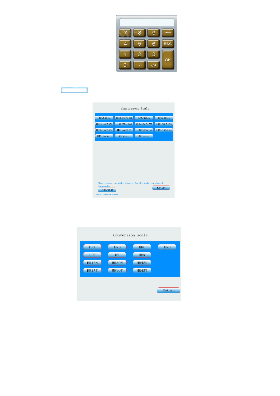
According to the hardness of materials (Table,1) select test scale (follow tips choose indenter)
For example: test the hardness of HRC:
Push the diamond indenter (5) towards the spindle hole, snapping the bearing surface, the flat face of the indenter towards indenter screws
(4), slightly tightened.
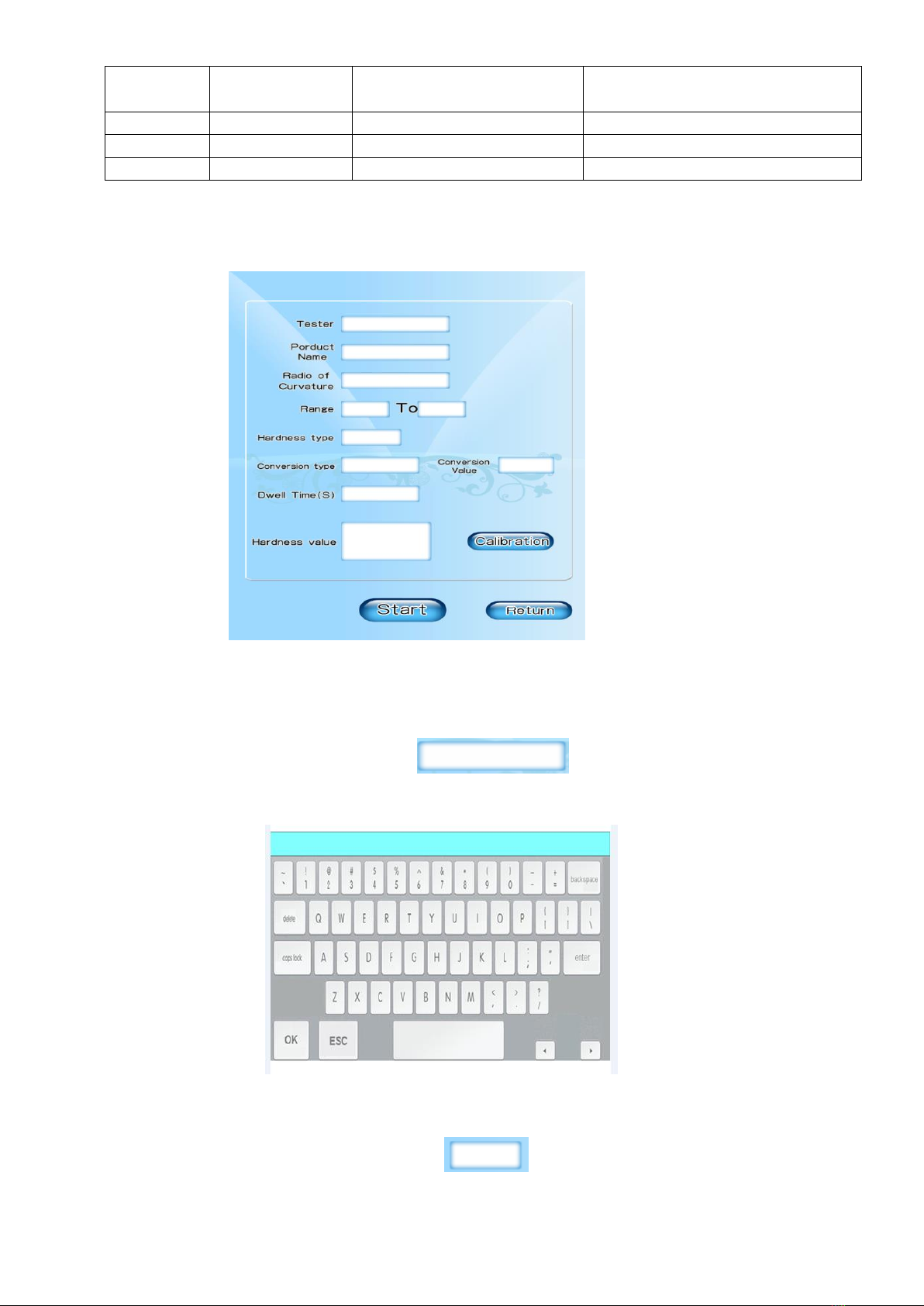
Turn on the power switch, the screen reach to operating interface.
Click on the “hardness type”, select HRC; if you need to change hardness type please click “conversion type”.
Click “dwell time”, select 5s. turn the rotating wheel (8) clockwise, lift up the working table (6). The specimen slowly touches the indenter
without any shock until the tester displays 580~610; at this time, the working table (6) stops lifting up, the hardness tester load test force
automatically. (When the working table moves up too fast and the screen display a value over610, the buzzer produces a long sound,
showing the operation is not correct. At this point, the buzzer sounds, it means the operation is wrong. The working table (6) should be
lowered and the position be changed for another test.
Load the test force automatically and the dwell time is 5s. At this time, 5s to 0s counts down, the dwell time is over, then the machine works
and unload the test force automatically. When the buzzer sounds, read out the hardness value displayed on the screen.
Note: During the loading and unloading of the test force, it prohibited turning the load change hand wheel (9), otherwise you would damage
the gears, and cause the disorder to the test force.
According to qualification requirements, the first measurement should not be documented. Document hardness value starting from second
point and 3-5 points are necessary and use the average.
5Maintenance and Precautions
Before ex-factory this instrument is up to the state standards through overall test for delivery, but due to the causes of assembly and
disassembly, transportation or voltage, it may cause some changes in the instrument data. Generally, it can be handled as follows:
Without loading indenter, apply 29420N test force to press several times in each starting of the instrument, so as to eliminate mechanical
deformation amount, make electric components in normal operation and decrease test errors.
Loading and unloading signal of each level test force is feedback by the sensor, and the output signal of the sensor is very sensitive. So, we
equip the anti-interference assembly in the circuit. But in order to ensure the instrument normal work and avoid unnecessary damage, the
instrument should avoid using around strong current interference source.
The test force must be perpendicular to the surface of the test piece at the time of loading, so the device cannot test the parts with surface of
inclined plane.
The instrument power source should be reliably grounded and have a voltage stabilizing device.
The instrument will issue some noise in the process of loading and unloading; it is a normal phenomenon that the loading device is
automatically adjusting.
The active surface of such as the lifting screw (5) should be periodically lubricated with grease.
Turn off the power source after the test is completed.
The instrument should be kept clean and covered with dust shield after finishing the test. The hardness blocks and the ball indenter should be
coated with antirust oil to prevent rusting.
The instrument should do periodic inspection, at least once a year to ensure the accuracy of the hardness tester.
(Table 5)
Phenomenon
Possible causes
Troubleshooting
Boot, screen do not react
1 Power do not supply
2 Blown fuse
1 check power supply
2 replace fuse (the spare)
Boot Key failure
The instrument is in a state of non-working
Boot and wait a moment
Lifting screw stuck
the gap between the lifting screw is small, fine
thread or dirt may cause stuck
Take off the protective cover of the lifting screw with a clean
cloth to wipe thread Hold the rotary wheel with both hands, lift
up and down the screw (Disable sandpaper friction screw)
The deviation of hardness
is large.
1 Indenter damage
2 Place the instrument is not level
3Total test force or indenter selection error
1Replace the diamond indenter or ball indenter
2Horizontal calibration Hardness Tester
3selection of test force and indenter follow table.1
Table of contents
Other Bms Bulut Makina Test Equipment manuals

Bms Bulut Makina
Bms Bulut Makina HTP 1600 User manual

Bms Bulut Makina
Bms Bulut Makina HARTIP-4100 Quick start guide

Bms Bulut Makina
Bms Bulut Makina 3000-OBPC Quick start guide

Bms Bulut Makina
Bms Bulut Makina BMS 200-RBOV Quick start guide

Bms Bulut Makina
Bms Bulut Makina BMS 3000-OBLC Quick start guide

Bms Bulut Makina
Bms Bulut Makina DIGIROCK-RB Quick start guide

Bms Bulut Makina
Bms Bulut Makina JB-300S Quick start guide

Bms Bulut Makina
Bms Bulut Makina 3000-OBPC User manual

Bms Bulut Makina
Bms Bulut Makina Hartip-3210 User manual

Bms Bulut Makina
Bms Bulut Makina HARTIP 3000+ User manual