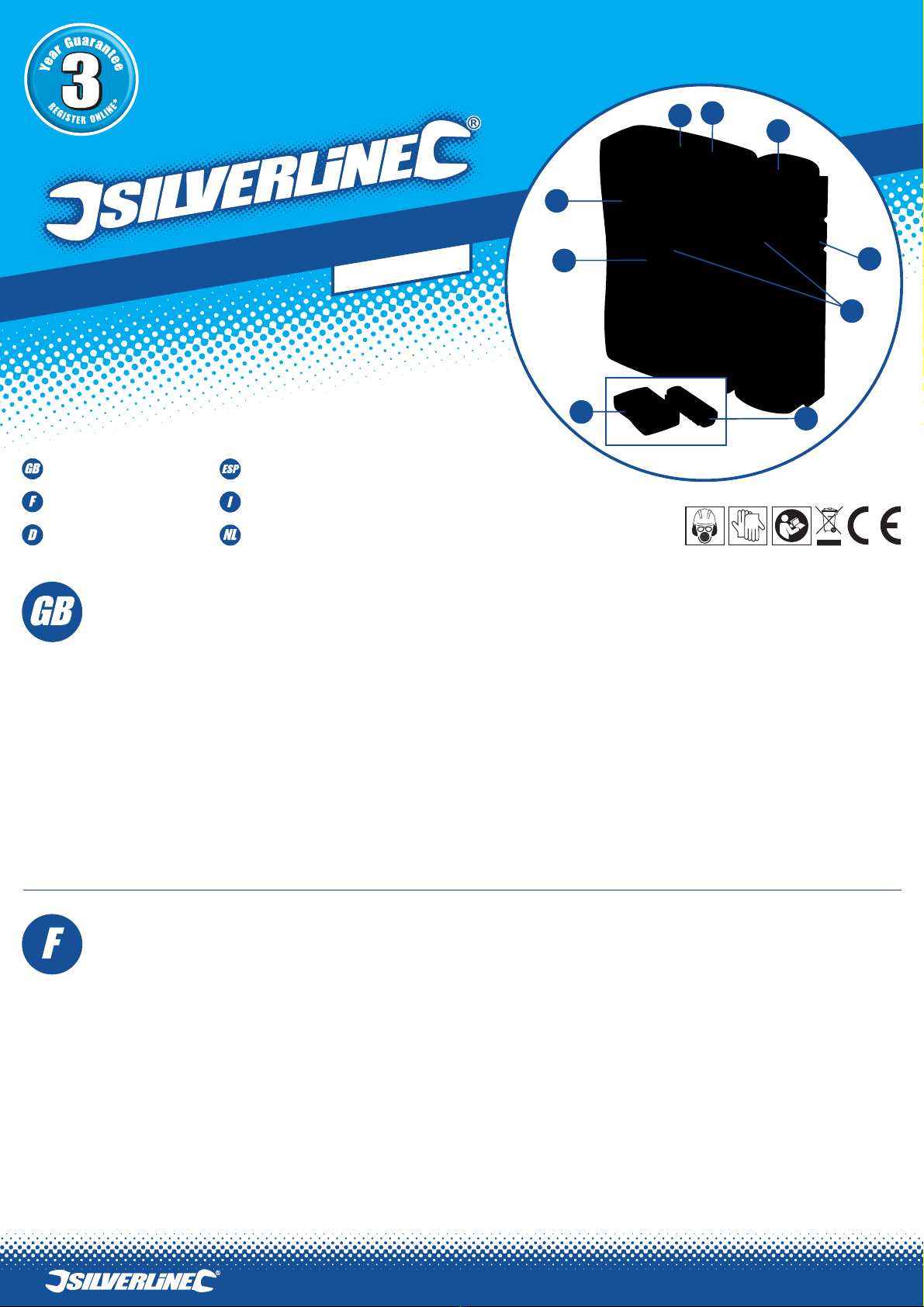
1) Sender („MASTER”)
2) 6P6C-Buchse am Sender
3) 8P8C-Buchse am Sender
4) 8P8C-Buchse am Empfänger
5) Abnehmbarer
Empfänger („REMOTE“)
6) 6P6C-Buchse am Empfänger
7) Ein-/Ausschalter
8) Betriebsanzeige
9) LED-Verbindungsanzeiger
• „ON“ – Standardgeschwindigkeit: Betriebsanzeige (8) blinkt schnell.
• „S” – Niedrige Geschwindigkeit: Betriebsanzeige (8) blinkt langsam und die Testergebnisse
werden zur leichteren Ablesbarkeit in langsamerer Abfolge angezeigt.
Betrieb
• Wechseln Sie die Batterie, falls die Anzeigelampen nicht mehr hell leuchten.
Kabel prüfen
WICHTIGER HINWEIS: Bitte beachten Sie, dass die „G“-Verbindung nur bei der Überprüfung von
Kabeln mit Schirmanschluss (Anschlussstecker mit leitender Oberfläche und Kabel mit geflochtener
oder Folienummantelung um den innenliegenden Drähten) angezeigt wird.
1. Stecken Sie ein Kabelende in die entsprechende Buchse am Sender (1) und das andere Ende in
die jeweilige Buchse am Empfänger (5).
2. Stellen Sie den Ein-/Ausschalter (7) auf „ON” (bzw. „S”).
3. Die LED-Verbindungsanzeiger (9) leuchten nun gemäß der nachfolgenden Beschreibung auf.
4. Falls keine Leuchtdiode aufleuchtet, vergewissern Sie sich, dass die Kabel ordnungsgemäß
angeschlossen sind und überprüfen Sie die Batterie.
Keine störung
• RJ45-Kabel: Die LED-Verbindungsanzeiger (9) an Sender und Empfänger leuchten der Reihe nach
von 1 bis G auf.
• RJ11-Kabel: Der Reihe nach von 1 bis G am Sender und 2, 3, 4, 5 am Empfänger.
Offener stromkreis
(Ader nicht angeschlossen)
• Wenn ein Kabel, z.B. Ader 3, an einem offenen Stromkreis anliegt, leuchten die LEDs für Ader 3 an
Sender und Empfänger nicht auf.
• Wenn mehrere Kabel an einem offenen Stromkreis anliegen, leuchten die entsprechenden LEDs
nicht auf.
• Wenn weniger als zwei Adern angeschlossen sind, leuchten ebenfalls keine LEDs auf.
Kurzschluss
(Ader falsch angeschlossen)
• Bei einem falsch angeschlossenen Kabelpaar, z.B.Ader 2 und Ader 4, leuchten die folgenden
LEDs auf:
Aufgrund der fortlaufenden Weiterentwicklung unserer Produkte können sich die technischen Daten
von Silverline-Produkten ohne vorherige Ankündigung ändern.
Bestimmungsgemäße Verwendung
Dieser Netzwerktester ist mit 8P8C- und 6P6C-Buchsen zur Überprüfung von RJ11- und RJ45-Kabeln
und -Netzwerkanschlüssen ausgestattet. Das Gerät kann fehlerhafte Anschlüsse, Kurzschlüsse und
Unterbrechungen anzeigen.
Vor Inbetriebnahme
Anschließen der batterie
Für den Betrieb dieses Gerätes wird eine 9-V-Blockbatterie (nicht im Lieferumfang enthalten) benötigt.
1. Schieben Sie zum Öffnen des Batteriefachs die Abdeckung auf der Rückseite des Senders
(1) ab.
2. Schließen Sie die Batterie an, indem Sie die Batteriepole und die Anschlüsse fest verbinden und
dabei auf die Polung achten.
3. Legen Sie die Batterie in das Fach ein und schieben Sie die Abdeckung wieder zurück, um das
Fach zu schließen.
Betriebsgeschwindigkeit
• Das Gerät verfügt über zwei Betriebsgeschwindigkeiten, die sich über den Ein-/Ausschalter (7)
wählen lassen:
Sender: 1-2-3-4-5-6-7-8-G
Empfänger: 1-4-3-2-5-6-7-8-G
• Zwei falsch angeschlossene Kabelpaare:
Die entsprechenden LEDs leuchten am Empfänger nicht auf, der Sender bleibt aber unverändert.
• Mehr als zwei Kabelpaare:
Die entsprechenden LEDs leuchten weder am Sender noch am Empfänger auf.
Netzwerk prüfen
WICHTIGER HINWEIS: „G” wird nur angezeigt, wenn die verwendeten Kabel und die
Netzwerkbuchsen über eine Masseverbindung verfügen.
Überprüfung der Verbindung zweier direkt miteinander verbundener Buchsen an Position A und
Position B:
1. Nehmen Sie alle Kabel von zusätzlich ans Netzwerk angeschlossenen Buchsen.
2. Schieben Sie den Empfänger (5) vom Sender (1) herunter, so dass die beiden Einheiten
voneinander getrennt sind.
3. Schließen Sie das Kabel des Senders (1) an Position A an die Netzwerkbuchse an.
4. Schließen Sie das Kabel des Empfängers (5) an Position B an die Netzwerkbuchse an.
Der Betrieb erfolgt gemäß „Kabel prüfen“ oben. Hinweis: Prüfen Sie vor der Überprüfung des
Netzwerks die zum Anschluss an das Netzwerk verwendeten Kabel auf Beschädigungen.
Wartung
• Führen Sie keine Wartungsversuche an diesem Gerät durch. Es enthält keine wartbaren Teile.
• Halten Sie die Gerätebuchsen stets frei von Staub.
• Bewahren Sie dieses Gerät zusammen mit der Bedienungsanleitung in der mitgelieferten Hülle auf.
• Nehmen Sie bei Nichtgebrauch über einen längeren Zeitraum die Batterie aus dem Gerät.
Entsorgung
Beachten Sie bei der Entsorgung von defekten und nicht mehr reparablen Elektro- und
Elektronikgeräten die geltenden Vorschriften und Gesetze.
• Elektrische und elektronische Altgeräte nicht über den Hausmüll entsorgen.
• Lassen Sie sich von der zuständigen Behörde bezüglich der ordnungsgemäßen
Entsorgung von Elektro- und Elektronikgeräten beraten.
1) Unidad principal
2) Entrada 6P6C - Unidad principal
3) Entrada 8P8C - Unidad principal
4) Entrada 8P8C - Unidad remota
5) Unidad remota
6) Entrada 6P6C - Unidad remota
7) Interruptor de
encendido/apagado
8) Luz indicadora de encendido
9) Indicadores LED
• S - Velocidad lenta, la luz indicadora de encendido (8) se mueve rápidamente y los resultados son
mostrados a velocidad lenta para leerlos más fácilmente.
Funcionamiento
• Si la luz del comprobador se debilita, proceda a cambiar la pila.
Comprobación de un cable
IMPORTANTE: Tenga en cuenta que la conexión “G” solo funcionará con cables con conexión a tierra
(Enchufes con superficie conductiva y cable trenzado envuelto alrededor del cable interno).
1. Inserte el extremo del cable en el conector adecuado de la unidad principal (1) y el otro extremo
en la unidad remota (5).
2. Deslice el interruptor de encendido/apagado (7) en posición “ON” o “S”.
3. Ahora los indicadores LED (9) se deberían iluminar de acuerdo al ajuste seleccionado.
4. Si los LED no se iluminan, compruebe que los cables estén correctamente colocados y el
estado de la pila.
No hay fallo
• Cables RJ45: Los indicadores LED (9) de la unidad principal (1) y remota (5) se iluminarán desde
número 1 hasta la letra G.
• Cables RJ11: Las luces indicadoras de la unidad principal y remota se iluminarán desde número 1
hasta la letra G en la unidad principal y 2, 3, 4, 5, en la unidad remota.
Circuito abierto
(Cable no conectado en el terminal)
• Si uno de los cables muestra el Nº 3, indicará que hay un circuito abierto. La luz Nº 3 se iluminará
en la unidad principal pero no en la unidad remota.
• Si existen varios cables con circuito abierto, las luces indicadoras no se encenderán.
• Si hay menos de dos cables conectados, las luces no se iluminarán.
Cortocircuito
(Cable conectado en el terminal incorrecto)
• Cuando un par de cables estén conectados de forma incorrecta, por ejemplo Nº 2 y Nº 4, se
iluminarán las siguientes luces:
Unidad principal: 1-2-3-4-5-6-7-8-G
Como parte de nuestra política de desarrollo de productos, los datos técnicos de los productos
Silverline pueden cambiar sin previo aviso.
Aplicaciones
Comprobador de cable LAN con tomas 6P6C y 8P8C para comprobar tomas y cables de red RJ11 y
RJ45. Esta herramienta puede comprobar conexiones incorrectas, cortocircuito y circuitos abiertos.
Antes De Usar
Montaje de la pila
Este producto requiere una pila de 9 V (no incluida)
1. Deslice la tapa situada en la parte posterior de la unidad principal (1) para abrir el
compartimiento dónde se coloca la pila.
2. Coloque la pila - Alinee la pila con los conectores de manera que los bordes de la pila queden
bien ajustados.
3. Inserte la pila en el compartimento y vuelva a cerrar la tapa deslizante.
Velocidad de funcionamiento
• El comprobador dispone de 2 velocidades de funcionamiento las cuales se pueden seleccionar
mediante el interruptor de encendido/apagado (7):
• ENCENDIDO “ON” - Velocidad estándar, la luz indicadora de encendido (8) se mueve rápidamente.
Unidad remota: 1-4-3-2-5-6-7-8-G
• Dos pares de cables conectados incorrectamente:
• Las luces correspondientes no se iluminarán en la unidad remota mientras la unidad principal se
mantendrá sin cambios.
• Más de dos pares de cables:
Las luces correspondientes no se iluminarán en la unidad principal ni en la unidad remota.
Comprobar una red
IMPORTANTE: “G” solo se iluminará cuando se estén utilizando cables con conexión a tierra
conectados a tomas con conexión a tierra.
Para comprobar la conexión entre la toma A la cual está conectada directamente con la toma B:
1. Desconecte cualquiera de los cables que estén conectados en la red.
2. Separe las dos unidades deslizando la unidad principal (1) de la unidad remota (5).
3. Conecte el cable de la unidad principal (1) con la toma de conexión A.
4. Conecte el cable de la unidad remota (5) con la toma de conexión B.
Continúe siguiendo las instrucciones descritas anteriormente en la sección “comprobación del cable”.
Nota: Antes de comprobar la red, asegúrese de que todos los cables estén en buen estado.
Mantenimiento
• No intente reparar esta herramienta usted mismo. No contiene piezas que se puedan reparar.
• Mantenga los conectores limpios y sin polvo.
• Guarde esta herramienta siempre en su bolsa junto al manual de instrucciones.
• Se recomienda retirar las pilas cuando no vaya a utilizar esta herramienta durante un largo
periodo de tiempo.
Reciclaje
Deshágase siempre de los aparatos eléctricos adecuadamente respetando las normas de reciclaje
indicadas en su país.
• No deseche los aparatos eléctricos junto con la basura convencional. Recíclelos siempre en
puntos de reciclaje.
• Póngase en contacto con la autoridad local encargada de la gestión de residuos para obtener más
información sobre cómo reciclar este tipo de aparatos correctamente.
1) Unità master
2) Ingresso 6P6C - Unità master
3) Ingresso 8P8C - Unità master
4) Ingresso 8P8C -Unità remota
5) Unità remota
6) Ingresso 6P6C - Unità Remota
7) Interruttore On / Off
8) Spia luminosa
9) Indicatori LED di collegamento
Funzionamento
• Se le luci appaiono fioca, montare una nuova batteria
Testando un cavo
IMPORTANTE: Si prega di notare il collegamento ‘G’ indica solo i cavi se si testa con un collegamento
a massa (spine di collegamento con una superficie conduttiva e cavo con treccia o manicotto di
stagnola avvolto ai cavi interni).
1. Inserire un’estremità del cavo nella presa appropriata sull’unità master (1), l’altra estremità
nella presa appropriata nell’unità remota (5)
2. Far scorrere l’interruttore On / Off (7) su ON (o S)
3. Gli indicatori a LED (9) devono illuminare conformemente alle indicazioni qui di seguito
4. Se nessuna luce si illumina, controllare che i cavi siano collegati correttamente e controllare
la batteria
Nessun guasto
• I cavi RJ45: Gli indicatori a LED (9) sull’unità principale e unità remota si accendono in sequenza
da 1 a G
• RJ11 cavi: 1 a G sull’unità principale, 2, 3, 4, 5 sull’unità remota
Circuito aperto
(Cavo non collegato al terminale)
• Se un filo, diciamo No. 3, ha un circuito aperto, la luce No.3 sull’unità principale e remota non
si accenderà
• Se alcuni cavi hanno un circuito aperto, le luci rispettive non si accendono
• Se meno di due cavi sono collegati, neanche una luce si accende
Cortocircuito
(Filo collegato al terminale sbagliato)
• Una coppia collegate correttamente, per esempio n ° 2 e n ° 4, le luci seguenti si accendono:
Unità master: 1-2-3-4-5-6-7-8-G
Unità remota: 1-4-3-2-5-6-7-8-G
• Doppia coppia collegata in modo sbagliato:
Le luci corrispondenti non si accenderanno su l’unità remota mentre l’unità master rimarà
Come parte del nostro continuo sviluppo dei prodotti, le specifiche dei prodotti Silverline possono
essere modificati senza preavviso.
Uso Previsto
Questo Tester LAN ha 8P8C e 6P6C prese per i test RJ11 e cavi RJ45 e connessioni di rete. Il tester
può indicare collegamenti errati, cortocircuiti e circuiti aperti.
Prima Dell’uso
Collegamento della batteria
Questo prodotto richiede una batteria da 9V (non in dotazione)
1. Far scorrere il pannello di copertura dal retro dell’unità master (1) per aprire il vano batteria
2. Collegare la batteria - Allineare la batteria con il connettore in modo che i terminali della
batteria e il connettore ad attacco- snap si incastrano in modo sicuro.
3. Inserire la batteria nel vano, e far scorrere il pannello posteriore in posizione
Velocità operative
• L’unità dispone di due velocità di funzionamento, selezionabili tramite l’interruttore On / Off (7):
• ON - Velocità standard, indicatore luminoso di alimentazione (8) lampeggia rapidamente
• S - a bassa velocità, indicatore luminoso di alimentazione (8) lampeggia lentamente ed i risultati
del test vengono visualizzati in una progressione più lenta per facilitarne la lettura
• Più di due coppie:
Le luci corrispondenti non si accenderanno sul master o unità remota
Verifica di una rete
IMPORTANTE: ‘G’ indica solo se i cavi utilizzati hanno un collegamento a massa e le prese di rete
hanno un collegamento a massa / messa a terra.
Per verificare la connessione tra la presa di posizione in A, che è direttamente collegata alla presa
nella posizione B
1. Scollegare tutti i cavi con prese di corrente supplementari collegati in rete
2. Far scorrere l’unità remota (5) spegnere l’unità master (1) in modo che le due unità sono separate
3. Collegare il cavo dall’unità master (1) alla presa di rete presso la sede A
4. Collegare il cavo da unità remota (5) alla presa di rete nella posizione B
Funzionamento come per ‘Testando un cavo’ come sopra. Nota: Controllare l’integrità dei cavi che si
utilizza per collegarsi alla rete prima di testare la rete.
Manutenzione
• Non tentare di riparare questo prodotto. Non contiene parti riparabili
• Tenere le prese su questo prodotto libera di polvere
• Conservare il prodotto nel sacchetto fornito, insieme al foglietto illustrativo
• Se il prodotto non verrà utilizzato per un lungo periodo di tempo, si consiglia di rimuovere la batteria
Smaltimento
Rispettare sempre le normative nazionali per lo smaltimento di apparecchiature elettriche ed
elettroniche (RAEE), che non è funzionale e non sono vitali per la riparazione.
• Non gettare utensili elettrici, o altri rifiuti di apparecchiature elettriche ed elettroniche (RAEE), con
i rifiuti domestici
• Contattare l’autorità locale di smaltimento rifiuti per informazioni sul modo corretto di smaltire
apparecchiature elettriche ed elettroniche (RAEE)
1) Hoofdkastje
2) 6P6C ingang - hoofdkastje
3) 8P8C ingang - hoofdkastje
4) 8P8C uitgang - bedienkastje
5) Bedienkastje
6) 6P6C ingang - bedienkastje
7) Aan-/uitschakelaar
8) Stroom indicatorlichtje
9) LED aansluiting indicators
www.silverlinetools.com
Technische daten
Batterie: 1 Stck. 9-V-Blockbatterie (PP3)
LED-Anzeigen: 2 x 9 Stck.
Anschlüsse: 2 x 6P6C, 2 x 8P8C
Abmessungen
(H x B x T): 105 x 100 x 28 mm
Gewicht: 125 g
Características
técnicas
Pila: 1 pila (PP3) de 9 V
Indicadores LED: 2 x 9 indicadores
Conectores: 2 x 6P6C y 2 x 8P8C
Dimensiones
(A x An x P): 105 x 100 x 28 mm
Peso: 125 g
Specifiche tecniche
Batteria: 1 x 9V (PP3)
Indicatori a LED: 2 x 9
Connettori: 2 x 6P6C, 2 x 8P8C
Dimensioni
(H x L x P): 105 x 100 x 28mm
Peso: 125g
Specificaties
Accu: 1 x 9 V (PPE3)
LED indicators: 2 x 9
Aansluitingen: 2 x 6P6C, 2 x 8P8C
Afmetingen
(H x B x L): 105 x 100 x 28 mm
Gewicht: 125 g
• ON - standaard snelheid, waarbij het indicatorlichtje (8) snel knippert
• S - langzame snelheid, waarbij het indicatorlichtje (8) langzaam knippert en de resultaten in een
langzaam verloop worden weergegeven voor een gemakkelijkere aflezing
Gebruik
Wanneer het indicatorlichtje zwak wordt, vervangt u de batterij
Het testen van een kabel
WAARSCHUWING: De ‘G’ aansluiting werkt enkel bij het testen van kabels met een aardeverbinding
(stekkers met een geleidend oppervlak en kabel met gevlochten of met folie bedekte mouw op
de binnenkabels)
1. Steek het ene einde van de kabel in de geschikte ingang van het hoofdkastje (1) en het andere
einde in de geschikte ingang van het bedienkastje
2. Schuif de aan-/uitschakelaar (7) op ‘ON’ (of ‘S’)
3. LED aansluiting indicators (9) dienen nu te ontbranden
4. Wanneer het lichtje niet ontbrand controleert u de aansluiting van de kabel en de batterij
Geen fout
• RJ45 kabels: de LED aansluiting indicators (9) op het hoofd- en het bedienkastje zullen sequentieel
van 1 tot G ontbranden
• RJ11 kabels: 1 tot G op het hoofdkastje en 2, 3, 4, 5, op het bedienkastje
Open stroomkringen
(Draad niet op de ingang aangesloten)
• Wanneer één draad, zeg nr. 3, een open stroomring heeft zullen de nr. 3 lichtjes op het hoofdkastje
en het bedienkastje ontbranden
• Wanneer een aantal draden een open stroomkring hebben zullen de lichtjes niet ontbranden
• Wanneer minder dan twee draden aangesloten zijn, branden er geen lichtjes
Open stroomkring
(Draad aangesloten op de verkeerde ingang)
• Bij een verkeerde aansluiting van een paar draden, bijvoorbeeld nr. 2 en 4, ontbranden de
volgende lichtjes:
Met het oog op onze aanhoudende productontwikkeling kunnen de specificaties van Silverline-
producten zonder voorafgaande kennisgeving worden gewijzigd.
Gebruiksdoel
De tester is voorzien van 8P8C en 6P6C aansluitingen voor het testen van RJ11 en RJ45 kabels en
netwerkaansluitingen. De tester geeft onjuiste aansluitingen, kortsluitingen en open
stroomkringen aan.
Voor Gebruik
Het aansluiten van de batterij
De LAN tester vereist een 9 V batterij (niet inbegrepen)
1. Schuif het dek paneel van de achterzijde van het hoofdkastje (1) voor het openen van het
batterijcompartiment
2. Sluit de batterij aan - lijn de batterij met de aansluitingen uit en klik deze samen
3. Plaats de batterij in het compartiment en sluit het dek paneel
Werksnelheid
• De eenheid heeft twee werksnelheden welke geselecteerd kunnen worden via de aan-/en
uitschakelaar (7)
Hoofdkastje: 1-2-3-4-5-6-7-8-G
Bedienkastje: 1-4-3-2-5-6-7-8-G
• Twee paar onjuist aangesloten:
De lichtjes zullen niet ontbranden op het bedienkastje, terwijl het hoofdkastje ongeladen blijft
• Meer dan twee paar:
De lichtjes zullen zowel op het hoofd- als het bedienkastje uit blijven
Het testen van een netwerk
WAARSCHUWING: ‘G’ geeft enkel aan of de gebruikte kabels en netwerkaansluitingen voorzien zijn
van een aardeaansluiting
Het testen van de aansluiting tussen een stopcontact op locatie A, welke direct is verbonden aan een
stopcontact op locatie B
1. Ontkoppel kabels van stopcontacten aangesloten op het netwerk
2. Schuif het bedienkastje (5) van het hoofdkastje (1) zodat deze gescheiden zijn
3. Sluit de kabel van het hoofdkastje (1) op de netwerkingang op locatie A aan
4. Sluit de kabel van het bedienkastje (5) op de netwerkingang op locatie B aan
Gebruik als ‘Het testen van een kabel’ hier boven. LET OP: Controleer de volledigheid van de kabels
voordat u het netwerk controleert
Onderhoud
• Probeer de tester niet te repareren. Het bevat niet repareerbare delen
• Houd de ingangen van de tester stofvrij
• Berg de tester in de buidel samen met de instructies op
• Wanneer de tester voor langere tijd niet gebruikt wordt verwijderd u de batterij
Verwijdering
Bij de verwijdering van elektrisch apparatuur neemt u de nationale voorschriften in acht.
• Elektrische en elektronische apparaten en accu’s mogen niet met uw huishoudelijk afval
worden weggegooid
• Neem contact op met uw gemeente voor informatie betreffende de verwijdering van
elektrisch apparatuur
539465_Z1PKGSAF1.indd 2 02/04/2014 11:47