ProT Ar-Ge FADOS7F1 User manual

1
Endüstriyel Proje Tasarım Ar-Ge Ltd. Şti.
Industrial Project Design R&D Co. Ltd.
FADOS7F1 (10V3)
FAULT DETECTOR AND PC OSCILLOSCOPE
USER MANUAL

2
PRODUCT DESCRIPTION
FADOS7F1 Fault Detector and PC Oscilloscope is basically computer-based VI
(Voltage-Current) test equipment. It connects to PC via USB port and works 5V
voltage by taking energy from USB port. FADOS7F1 works by applying sinusoidal
voltage through a serial resistor point of touched on circuit and voltage-current graph
is displayed on the computer screen. In addition to this feature, computer software
by analyzing voltage-current graph to displays equivalent circuit diagram and values
of electronic components. Equivalent circuit diagram and measurement of electronic
components values features make successful analyze, but sometimes software
makes possibility of faulty analysis so that it does not used for measurement on the
circuit, these features used for convenience to user in giving an information for
finding faulty easily.
Feature of Dual Channel VI test, solid and faulty electronic cards comparable with
touch of same points at the same time and using this method, faulty points out of
tolerance can be detected.
Using feature of recording reference values to memory and comparing data from
memory, it can test easily electronic cards.
In addition to the basic features, FADOS7F1 VI Tester can also be used dual-channel
oscilloscope, square wave generator and analogue voltage output.

3
SECURITY
1- FADOS7F1 is produced by using lead-free solder and designed in accordance
CE regulations; users must use the following usage rules.
2- Chassis must be isolated and grounded. Connect the chassis ground
connection point of the probe is the same as your computer, careful to avoid
the potential difference.
3- Feature of oscilloscope, if probe key is set to 1X, it measures ±5
Voltage, probe key is set to 10X, it measures ±50 Voltage. Do not use
above these limits of voltage.
4- It tests electronic cards without giving to energy. Before test, electronic card
and the devices must be made high-voltage capacitor discharges.
5- The users of this equipment must have knowledge and experience to repair of
electronic cards. Thus, during using FADOS7F1, do not this mistakes such as
touch chassis to high-voltage, non-isolated ground, test high-voltage capacitor
discharges. Without enough knowledge and experience in this subject, keep
away high voltages such as mains voltage which can damage the system and
themselves.
6- Giving high-voltage from probes, series resistors which contained in the device
damaged and makes the circuit an open circuit. In this case, the computer
port which is connected device via USB port damaged but observed in other
parts of the computer is not damaged.

4
TECHNICAL FEATURES
A- FAULT DETECTION FEATURE:
Output Voltage : ±1V, ±2V, ±5V, ±10V
Output Resistance : Current Level: Low : 47 KΩ
Medium : 2,7 KΩ
High : 550 Ohm
Short Circuit Current : Low Current : 212 μA (10V)
Medium Current : 3.7 mA (10V)
High Current : 18 mA (10V)
Test Frequency : Very Low Frequency : 2 Hz
Low2 Frequency : 3.4 Hz
Low1 Frequency : 10.3 Hz
Test Frequency : 27.3 Hz
High Frequency : 780 Hz
Other Feature :1: Automatic selection steps of voltage, current, frequency.
2: Equivalent circuit diagram.
3: Resistor, capacitors, diodes etc measurement.
4: Recording data and comparing with recorded data.
5: 3 graphs at different adjustments can be screened
simultaneously.
B- PC OSCILLOSCOPE FEATURES:
Sampling Rate : 400 K/S
Input Voltage : Probe 1X: ±5 V Probe10X: ±50 V
Channel / ADC : 2 Channel / 12 Bit
Sensivity : 2.5 mV
Image Rate : 0.02 mS/div….100 mS/div
Instant Memory : 64 Kbyte
C- DIGITAL AND ANALOG OUTPUT:
Output : Channel 2
Output Voltage : -5V….+5V (Adjustable)
Frequency (Digital): From 0.2KHz to 25KHz
Table 1: FADOS 7F1 Technical Features

5
Product Content Physical Features (Without Accessories)
1 FADOS7F1 Product Dimensions : 75 mm Width
2 Oscilloscope Probes : 40 mm Height
1 USB Cable : 20 mm Deep
1 Software CD Weights : 450 gram with all accessories
1 Hand Bag for FADOS7F1
Picture 1: FADOS 7F1, USB Cable, Probes

6
CONTENTS
Page
PRODUCT DESCRIPTION .............................................................................. 2
SECURITY...................................................................................................... 3
TECHNICAL FEATURES .................................................................................. 4
PRODUCT CONTENT ............................................................................................... 5
PHYSICAL FEATURES (WITHOUT ACCESSORIES)............................................................. 5
FADOS 7F1 FAULT DETECTOR AND PC OSCILLOSCOPE................................ 7
USAGE AREAS ...................................................................................................... 7
UNIQUE FEATURES ................................................................................................ 7
INSTALLATION .....................................................................................................10
DRIVER INSTALLATION ..........................................................................................10
GENERAL USAGE INFORMATION ................................................................ 11
VI TEST –PROGRAM FEATURES OF FAULT DETECTON PART..................... 13
PASSIVE COMPONENTS R, L, C (RESISTOR, INDUCTOR, CAPACITOR)
CURRENT –VOLTAGE VI GRAPHS............................................................... 15
RESISTOR VI GRAPH.............................................................................................15
CAPACITOR VI GRAPH ..........................................................................................17
CAPACITOR QUALITY TEST AND RC CIRCUIT ...............................................................17
INDUCTOR VI GRAPH ............................................................................................19
SEMI CUNDOCTORS .................................................................................... 20
DIODE,ZENER DIODE VI GRAPH..............................................................................20
TRANSISTOR –TRIAC –THYRISTOR –FET –IGBT VI GRAPH ..........................................22
TESTING INTEGRATED (IC - SMD INTEGRATES)........................................ 23
ELECTRONIC CIRCUIT REGISTRATION MEMORY AND COMPARISION WITH
MEMORY...................................................................................................... 25
COMPARISION TESTING COMPONENTS OF ELECTRONIC CIRCUIT .......... 26
3G –3 DIFFERENT GRAPH DISPLAY........................................................... 32
OSCILLOSCOPE –PROGRAM FEATURES..................................................... 33
RECOMMENDATIONS .................................................................................. 34
WARRANTY AND CONDITIONS................................................................... 35

7
FADOS 7F1 FAULT DETECTOR AND PC OSCILLOSCOPE
Fault Detector and PC Oscilloscope have been especially developed to determine
faults at all type electronic cards by ProT Ar-Ge Industrial Project Design R&D Ltd.
Co. The main purpose, make it easier to find fault of electronic cards. It is included
oscilloscope, signal source, multimeter etc.
Usage Areas
ECU Automotive electronic cards, servo-step motor drivers, cards of medical devices,
military electronic cards, computer and monitor cards, television-audio-radio cards,
cards of textile machines, mobile phone electronic cards etc. (all type electronic
cards.)
Unique Features
Equivalent circuit diagram and measuring values of all components features are
unique in the World. As an example; if resistor connected parallel to capacitor, it
shows circuit diagram and value of them at the same time.
Picture 2: FADOS 7F1

8
FADOS 7F1 includes 7 important functions:
1. Double - Channel Fault Detection (VI Graph)
Comparing solid and faulty card without giving energy.
2. Equivalent Circuit Diagram
Composing R, C, or Diode Circuit Diagram according to the point touched.
3. Measuring of Resistor, Capacitor, and Diode
Feature of measuring the value of touched point.
4. Fault Detection by Comparison from Memory
By recording solid card to memory, comparing faulty card from memory.
5. Double –Channel Digital PC Oscilloscope
As occasion may require, device can be used as oscilloscope.
6. Square Wave Signal Output
Ch.1 is used as oscilloscope and Ch.2 is used as signal generator.
7. Analogue Voltage Output
Ch.1 is used as oscilloscope and Ch.2 gives analog voltage output.

9
Picture 3: FADOS 7F1 Fault Detector –VI Tester Screen
Picture 4: FADOS 7F1 Oscilloscope –Analog Output Screen

10
INSTALLATION
1- Connect FADOS7F1 to PC via USB. Install drivers in CD.
2- Click FADOS7F1 SETUP.exe and install program.
3- Run FADOS7F1.exe
DRIVER INSTALLATION
1- Connect FADOS7F1 to PC via USB. Windows XP 'New Hardware Found' with
warning direct you to install the driver. Insert the CD into the CD rom and
install the driver.
2- Windows Vista and Windows 7 open Device Manager.
On the desktop right-click on My computer and click Properties of open
the Control Panel and double-click the System icon.
In the System Properties window click the Hardware tab.
In the Hardware tab click the Device Manager Button.
Or
Click Start
Click Settings
Click Control Panel
In the Control Panel double-click the Systems icon.
In the System Properties window click the Hardware tab.
In the Hardware tab click the Device Manager Button.
3- Find “Prot Ar-Ge FADOS7F1 Fault Detector” inside Universal Serial Bus
Controllers and click right then, select “update software driver”.
4- Select (Search for the best driver location) and click browse, find FADOS7F1
Driver’s folder.
5- Click OK and install driver.

11
Note: Each product has different calibration settings, so that please do not lost
program CD.
GENERAL USAGE INFORMATION
1. Product Oscilloscope –Analog Output screen pop-up and if you click Fault
Detector –VI Tester button, input screen Fault Detect.
2. Oscilloscope 1,8 V offset voltage is transmitted output through the internal
resistance of 1 MΩ. If you select 10X probes, this resistance is 10 MΩ. In this
case, the touched point, usually does not make any effect.
3. Open circuit’s graph is in the middle and horizontal position at Test-Fault
Detect screen. Current –Voltage Graph (VI) makes angle according to the
value of resistance, capacitor is like circle and ellipse, short circuit is vertical
position.
4. Middle current step if resistance values are high and VI graph is horizontal
axis, you can see more clearly high resistance value at low current step. If VI
graph is more closer to vertical axis, it means resistance value is low and
values can be read more clearly at high current step.
5. Usually, test capacitor at high frequency mode. If capacitor value is low, test
at low current step and if capacitor value is high, test high current step. If
capacitor value is like slim ellipse at high current step and vertical axis, you
can see value of capacitor by reducing frequency of the frequency step.
6. Solid integrated pin (without pin of supply and ground) is usually like double
reverse diode. Resistor or capacitor effects even as graph, observed double
reverse diode. Some integrated output can be observed one diode. But, if you
see pin of integrated like resistor, it means integrated is faulty.
7. Capacity test especially determines quality of electrolytic capacitor. If this
curve is horizontal, capacitor is quality. Low quality capacitor curve according

12
to horizontal makes an angle. If angle is more, capacitor is faulty. Due to
current this test may be misleading, while testing a capacitor at circuit.
Therefore considering this situation to test. For capacitor quality, the best
measurement in this product is done by looking at the Capacity Resistance
curve.
8. At fault detection important thing is graph display and interpret. First, try to
find fault with compare. In a short time you will learn difference between solid
and faulty card. The equivalent circuit and values are auxiliary elements. If
you always look equivalent circuit and values, it can take more times to detect
fault. This product interprets VI graph. The computer program composes
equivalent circuit diagram and shows values of components by interpreting
graph.

13
VI TEST –PROGRAM FEATURES OF FAULT DETECTON PART
FADOS 7F1 was developed by ProT Ar-Ge Industrial Project Design R&D Ltd. Co. for
finding fault of electronic cards.
While testing with V/I graph, do not apply power to card. Generally, probe chassis is
connected to card chassis and a signal is applied to touch point by the device. V/I
graph of this signal is seen at the screen. Signals scans from negative voltage to
positive voltage and when open circuit, it appears horizontally in the middle of the
screen.
It can test Mosfet, Thyristor, IGBT, Transistor, SCR and Triac etc. all electronic
components and integrated. All control buttons are placed to the left of the panel
used in fault detection.
Picture 5: Fault Detector –VI Tester Screen
14
Channel: Used to select channel.
Auto: When Auto is selected, according to feature of touched point, the most
appropriate values of voltage, frequency, and current steps are determined.
Voltage Step: FADOS 7F1 has various voltage steps ±1V, ±2V, ±5V, ±10V.
simultaneously.
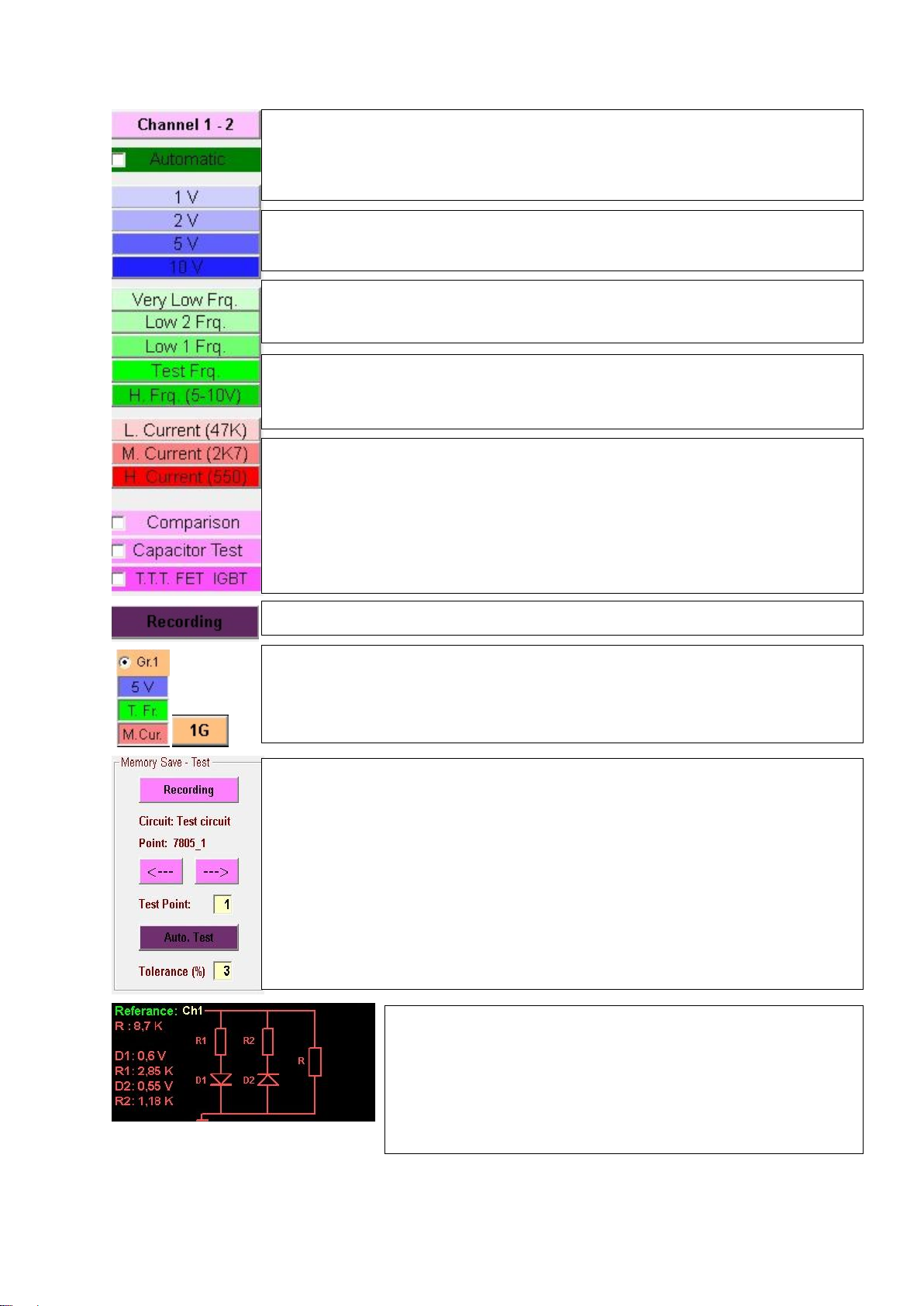
Reference: Channel1 indicates solid circuit, Channel2 indicates
faulty circuit or circuit to be tested. When saved at memory,
Reference=Channel1 is saved. Values of circuits composed of
resistance, capacitor, and diode are displayed; and circuit.
diagram is displayed
Grf: For 3 different steps, 3 different graphs are generated and fast passage is
possible at any time.
1G, 2G, 3G: 1, 2 or 3 graphs at different adjustments can be screened.
simultaneously.
Frequency Step: FADOS 7F1 has various frequency steps Very Low Freq., Low 2
Freq., Low 1 Freq., Test Freq., and High Freq.
Current Step: FADOS 7F1 has various current steps Low Current, Middle Current,
High Current.
Compare: If this option is selected, solid and faulty cards are compared by
touching probes to the same points of both cards.
Capacity Test: Capacity test determines quality of electrolytic capacitor.
TTT FET IGBT: If this option is selected, determines TTT, FET, IGBT etc. Type of
semi –conductors.
Recording: Opens file form and records; or opens recorded file.
Recording: Opens file form and records; or opens recorded file.
Circuit: Indicates name or code of point to be tested. Folder name in the system.
Point: Name or code of test point. Recorded as file name in the system.
: Goes to previous test point.
: Goes to next test point.
Test Point: Serial number of test point.
Auto Test: If tolerance of test point is lower than or equal to tolerance mentioned
below, it goes to next test point automatically.

15
PASSIVE COMPONENTS R, L, C (RESISTOR, INDUCTOR, CAPACITOR)
CURRENT –VOLTAGE VI GRAPHS
Resistor VI Graph
Resistor current –voltage (V/I) graph appears with a specific angle to horizon; and
resistor symbol and value are seen at the bottom of the graph. While resistors at
high values appear with angle close to horizontal axis, resistors at low values are
seen at screen with an angle close to vertical axis. Picture 6 and 7 display resistors
typical signals and values for the equivalent circuit.
High resistor generates a line close to horizontal line. So that, for testing high
resistance selects low current step. Low resistor generates a line close to vertical
line. So that, for testing low resistance selects high current step.
Picture 6: 33 kΩ and 470kΩ Resistors VI Graph, The Equivalent Circuit Diagram and
Value Measurement (Channel 1 Red - Channel 2 Blue)

16
Picture 7: Resistor VI Graph, The Equivalent Circuit Diagram and Value Measurement
Picture 8: Short Circuit and Resistor VI Graph

17
Capacitor VI Graph
Due to their energy storage characteristics, reactive components produce a phase
shift between voltage and current flow. This is displayed as a circular or elliptical
signature. Capacitor symbol and value are seen at the bottom. Picture 9 displays
capacitor typical signals and values for the equivalent circuit. High capacitor
generates vertical ellipse. For testing high capacitor select high current and low
frequency. Low capacitor generates horizontal ellipse. For testing low capacitor
(lower than 10 nF) select low current and high frequency.
Picture 9: Capacitor VI Graph, The Equivalent Circuit diagram and Value
Measurement
Capacitor Quality Test and RC Circuit
When “Capacitor Test” is selected, an additional curve displaying the quality of
capacitor appears. If this curve is at horizontal axis or close to it, quality is high; and
quality is low as much as the angle degree is high. High quality capacitor generates a
horizontal line.

18
Picture 10: High Quality Capacitor
Picture 11: Low Quality Capacitor

19
Picture 12: Capacitor and RC Circuit
If capacitor and resistor are parallel, elliptical shape makes an angle to horizon.
Inductor VI Graph
The diagram below shows the signature of a ferrite transformer primary winding with
the test voltage range set Low and test frequency set High. This demonstrates the
effect of a significant value of resistance causing the inductive ellipse to be tilted.

20
Picture 13: Inductor VI Graph, The Equivalent Circuit Diagram
SEMI CONDUCTORS
Diode –Zener Diode VI Graph
Diodes start to transmit current after high transmission voltage. For this reason,
diodes are seen horizontally at one part of the graph, and are seen vertically at the
other part. If cathode of diode is connected to chassis, a curve appears at horizontal
axis at negative voltage and before transmits voltage; and the curve appears at
vertical axis at transmit voltage. If anode of diode is at chassis, a curve appears to
down at negative voltage.
A Zener diode exhibits the same signature as a conventional diode for voltages below
the Zener voltage. When the reverse bias exceeds the Zener voltage, a low
resistance signature is displayed.
If diode and resistor are serial on circuit, after transmission, graph makes an angle to
horizon.
Table of contents


