Energx Dyna TF6000E User manual

OWNERS MANUAL
60707-023
EA8EL)fiw
-
-
-
-
-
-
-
-
-
-----
--
---
-
--
-
--
---
-
---
-
CORPORATION

READ AND UNDERSTANDALL INSTRUCTIONSIN
THE MANUAL BEFORE STARTING AND OPERATING
THE GENERATOR SET.
USING THIS MANUAL
Congratulations on your choice of an ENERGX gener-
ator set. You have selected
a
high-quality, precision-
engineered generator set designed and tested to give
you years of satisfactory portable service.
To get the best performance from your new engine
generator set, it is important that you carefully read and
follow the operating instruction in this manual.
Should you experience a problem please follow the
"Things To Check" near the end of this manual. The
warranty inthe back of this manualdescribes what you
can expect from ENERGX should you need service
assistance in the future.
PROPER USE AND INSTALLATION
You must be sure your new engine generator set is:
*
Properly serviced before starting
Operated in a well ventilated area
*
Exhaust gases are dispersed safely
Wired by a qualified electrician
Operated only for its designed purposes
*
Used only by operators who understand its
operation
Properly maintained
TABLE
OF CONTENTS
PAGE
INTRO
......................................
I
GUIDE TO PRODUCT SAFETY
................
A1
BASIC INFORMATION
.......................
B1
Specifications..
.........................
B1
Intended Uses
...........................
B1
Restricted Uses
.........................
B1
Unit Capabilities.
........................
B1
Where is Everything Located
..............
82
PREPARING THE UNIT
......................
C1
Unpacking the unit
......................
C1
Oil Requirements
........................
C2
Fuel Requirements.
......................
C2
Battery Installation.
......................
C3
BASIC OPERATION
.........................
Dl
Operating Procedure
.....................
Dl
Connecting the Loads..
..................
D3
Conserver operation
.....................
D3
Low Oil Shutdown Operation
..............
D3
INSTALLATION
.............................
El
Wiring
.................................
El
OPERATOR MAINTENANCE
..................
F1
Engine Care
............................
F1
Generator Care
..........................
F1
Unit Cleaning
...........................
F1
Things to Check before you call for Service
.
F2
.......................
ENERGX WARRANTY
COPY YOUR MODEL AND SERIAL
NUMBER HERE
Noother ENERGX generator has the same serial num-
ber as yours. It is important that you recordthe number
and other vital information here, if you should ever need
to contact us on this unit it will help us to respond to
your needs faster.
MODEL
................
SERIAL NUMBER..
......
DATE PURCHASED
......
DEALER.
...............

GUIDE
TO
PRODUCT SAFETY
This engine generator set has been designed and
manufactured to insure your personal safety. Improper
use can result in potential deadly hazards; from elec-
trical shock, exhaust gas asphyxiation, or fire. Please
read all safety instructionscarefully before installation
or use. Keep these instructions handy for future refer-
ence. Take special note and follow all warnings on the
unit and in the manuals.
CAUTION:
Possible Damage to Equip-
ment.CAUTION notes indicate any con-
[-]
dition or practice, which if not strictly
observed or remedied, could result in
damage or destruction of the equip-
ment.
WARNING:
Personal Danger. WARN-
ING notes indicate any condition or
practice, which
if
not strictly observed,
could result in personal injuryor possi-
ble loss of life.
a
ELECTRIC SHOCK
-
The output voltage pres-
ent in this equipment can cause a fatal electric
shock. This equipment must be operated by a
responsible person.
A. Do not allow anyone to operate the genera-
tor without proper instruction.
B. Guard against electric shock.
C. Avoid contact with live terminals or receptacles.
D. Useextreme care
if
operating this unit inrain or
snow.
E.
Use only three-pronggrounded receptacles and
extension cords.
F. Be sure the unit is properly grounded to an ex-
ternal ground rod driven into the earth.
2.
FIREHAZARD
-
Gasolineandother fuels always pre-
sent a hazard of possible explosion andlor fire.
A. Do not refuel when the engine is running or hot.
Allow the engine to cool at least two minutes
before refueling.
B. Keep fuel containers out of reach of children.
C. Do not smoke or use open flame near the
generator set or fuel tank.
D. Keep afire extinguisher nearbyand know its pro-
per use. Fire extinguishers rated ABC by NFPA
are appropriate.
E. Store fuel only inan approved container, andon-
ly in a well-ventilated area.
3.
DEADLY EXHAUST GAS
-
Exhaust fumes from any
gasoline engine contain carbon monoxide, an odor-
less and deadly gas that must be mixed with fresh
air.
A. Operate only in well ventilated areas.
B
.
Never operate indoors.
C.Never operate the unit in such a way as to allow
exhaust gasesto seep back into closed rooms(i.e.
through windows, walls or floors).
4.
NOISE HAZARD
-
Excessive noiseis not only tir-
ing, but continual exposure can lead to loss of
hearing.
.
A.Use hearing protection equipment when working
around this equipment for long periods of time.
B.Keep your neighbors in mind when permanently
installing this equipment.
5.
CLEANLINESS
-
Keep the generator and surrounding
area clean.
A.Remove all grease, ice,s.now or materials that
create slippery conditions around the unit.
B.Remove any rags or other material that could
create potential fire hazards.
C.Carefully wipe up any gas or oil spills before start-
ing the unit.
D.Never allow leaves or other flammable materialto
build up around the engine exhaust area.
6.
SERVICING EQUIPMENT
-
All service, including the
installation or replacement of service parts, should
be performed only by a qualified technician.
A.Use only factory approved repair parts.
B.Do not work on this equipment when fatigued.
C.Never remove the protective guards, cover or
receptacle panels while the engine is running.
D.Use extreme caution when working on electrical
components. Highoutput voltagesfrom this equip-
ment can cause serious injury or death.
E.When servicing this unit alwaysavoid hot mufflers,
exhaust manifolds,and engine parts.They all can
cause severe burns instantly.
F.Installingand wiring a home-standbygenerator is
not a "do it yourself" project.Consult a qualified,
licensed electricianor contractor. The installation
must comply with all national, state, and local
codes.

SPEClFlCATIONS
*Rating based on gasoline. For LP derate 1O0/0 for
natural gas derate 20%.
**CrankingPerformance at 80 Degree F. 190 CCA.
MODEL
Generator
Continuous Watts'
Volts
AMPs
Receptacles
NEMA 5-15 (120V)
NEMA 5-50 (120V)
N
EMA 6-30 (240V)
Engine
Size
Model
TYpe
Fuel Capacity
Fuel Consumption
Full Load gas
LP
NG
Starting System
Stop System
Low Oil Shutdown
Muffler
Complete Unit
Weight (dry)
Dimensions LxWxH
Dolly Wheels
Owner Must
Provide
Fuel
Oil Type
Oil Capacity
Battery Size
INTENDED USES
1.
These engine generator sets have been designed
primarily for portable use. Receptaclesare provided
inthe control panel on the generator for you to plug
inyour loads (portable appliances and tools). These
generatorsare designedwith full powercapabilities.
See unit capabilities for further explanation.
2. These units require large quantities of fresh air for
coolingof boththe engine and the generator. Fresh
air isdrawn from both the engine end and the gen-
eratorend and isexhaustedat the centerof the unit.
For safety, long life and adequate performance,
these units should never be run in small compart-
ments without positive fresh air flow.
TF4500E TF6000E
4000 5500
1201240 1201240
33.3116.7 45.8122.9
4
4
1 1
1 1
8HP 11HP
195437 254427
See Engine Shroud Above
Recoil For Type
----.--em--m-
41/* GAL
------------.
.87glhr 1.09glhr
6.'/#lhr 7.7#lhr
110CuFtlhr 155CuFtlhr
---------
RecoillElectric---------
--------------
Panel Switch
--------------
-----------------
Standard
-----------------
Super Low Tone with Spark
Arrestor
160 LBS 199 LBS
29x19~24 29x19x24
.----------.----.
Optional
-----------------
Unleaded Gas or LP or NG
10W-30 for Service SF, SE,
SD, SC. See engine manual
for additional info
23/4 Pints
3
Pints
Ul*' Ul*'
RESTRICTED USES
1.
DO NOT removefrom the cradle assembly. Remov-
al of the generator from the cradle assembly may
causeexcessivevibration and damagetothe engine
generator set.
2. DO NOT install and operate these portable genera-
tors in small compartment. (i.e. generator compart-
ment of vehicles, motor homes, or travel trailers)
Thesecompartments will not allow enough free flow
fresh air to reachthe engine generator set for cool-
-
ingandwill allowthe unit tooverheat damagingboth
the engine and the generator. Small compartments
will also develop hot spots where there isvery little
air flow and may cause a fire.
3.
DO
NOT attempt to operate this unit at 50 cycles.
These units are designed and are governedto oper-
ateat 60 Cycles only. Special units are available for
50 cycle operation.
UNIT CAPABILITIES
1. Generator Connections
-
These generators are
equipped with a patented full power feature. This
feature is designed to give the owner full rated
generator output from a SINGLE 120 volt outlet or
a SINGLE 240 volt outlet without the necessity of
having to carefully balance this 120volt load. Con-
ventional generators require splitting the 120 volt
loads and balancing them on two separate power
leads inorder to fully utilize the rated output of the
conventional generator.
FullPowerwindings use extra heavywire sothat
itcan safely carry the entire loadon a single 120volt
circuit. This eliminates the needto split and balance
the 120 volt load to avoid damaging the armature.
The operator usingthis generatorhasthe entire out-
put availablefrom asingle 120volt circuit or a single
240 volt circuit or a combination of 1201240volts cir-
cuits as long as the total load does not exceed the
engine power.
j
,j.
240
VOLTS
!
B!
)
1-
v
v
POWER
WINDING
G3
Fig. B-1
Typical Full Power generator
The followingcurrents(measuredinamps) are pro-
duced at 120volts and 240 volts for Models shown.
AMPS
@
120 VOLT 240 VOLTS
RECEPTACLE ID
MODEL
TF4500E
TF6000E 45.8 22.9
Table B-1
B1

SPECIFICATIONS
(continued)
2.
Starting Electric Motors
-
Electric motors require
much more current (amps)to start them than to run
them. Some moJors,particularly low cost split-phase
motors are very-hardtostart and require5to 7times
as much current to start them as to run them. Ca-
pacitor motors are easierto start and usually require
2to 4times as muchcurrent to start them as to run
them. Repulsion Inductionmotorsare the easiest to
start and usually require 1% to 2% times as much
to start them as to run them.
Most fractional horsepowermotors take about the
same amount of current to run them whether they
are of Repulsion-Induction (RI),Capacitor (Cap), or
Split-Phase(SP) type. The chart below shows the ap-
proximate current required to start and run various
types of sizes of 120 volt 60 cycle electric motors
under average load conditions.
RUNNING Sf
ARTlNG AMPS
HP AMPS SP CAP R
I
116 3.2 16 TO 22 6 TO 13 5 TO 8
114 4.5 22TO32 9TO18 7TO12
113 5.2 26TO35 10TO21 8TO17
112 7.2 NOT MADE 14 TO 29 11 TO 18
1 13.0 NOT MADE 26 TO 52 20 TO 33
and no harm is done. Under these conditions the
motor may revolvea few times when it isfirst turned
on, and then stop.
On the other hand,suppose an electric motor that
requiresjust a little moreoutput than the generator
can produce is connectedto it. It will run but will not
reach a high enough speed for the centrifugal switch
to disconnect the starting winding. The generator
output voltage, instead of being 120, maydrop to 70
or 80 volts. RUNNING THE GENERATOR UNDER
THESE CONDITIONS MAY RESULT IN BURNING
OUT THE GENERATOR ARMATURE AS WELL AS
THE MOTOR WINDINGS.
Because the heavy surge of current required for
starting motors is required for only an instant, the
generator will not be damaged
if
it can bring the
motor up to speed in a few seconds of time. If dif-
ficulty is experienced in starting motors, turn all
other electrical loads off and if possible reduce the
load on the electric motor.
3.
Motor Starting Capacity
-
listed below you will find
the motor starting capability of your engine genera-
tor set.
The figures givenabove are for average loadsuch
as a blower or fan. If the electric motor isconnected
to a hard starting load such as an air compressor,
itwill requiremore starting current. If it isconnected Trying to start a larger motor or a higher code (ie
to a light load, or no load such as a power saw, it
J
or
K)
motor may result indamage to both the gen-
will require less starting current. The exact require- erator and the electric motor, especially 120 volt
ment will also vary with the brand or design of the motors.
motor.
For 240 volt motor, the "running" current is half WHERE IS EVERYTHING LOCATED
as much as shown for the 120 volt motors of the
same size. Some dual voltage 1201240 volt motors
are difficult to start on 240 volts when driven by en-
ginelgeneratorsand can be started more easily when
connectedtooperateon 120volts. This isparticularly
true of "capacitor start-induction run" motors.
Sometimesa 240 volt motor which cannot be started
on the 240 volt circuit of a 1201240volt generatorcan
be started on a 120 volt circuit and then quickly
switched to the 240 volt circuit after it is started.This
can be done in applications where the motor is man-
ually controlled and is started under "no load" con-
ditions.
A self-excited generator responds differently to
severe overloading than atransformer connected to
a power line. To illustrate, suppose that a 240 volt
5
H.P.
"capacitor start-Induction Run" motor iscon-
nectedto a small transformer that would not be able
tosupply enough power to bring the motor up to op-
erating speed. It would be very severely overloaded
and probably would burn out in a short time. The
motor might also be damaged. When this motor is
connected to a self-excited4000 watt generator, its
output voltage drops to practically zero. Thus, there
is virtually no load on the generator or the engine,
1. Starter
2. Battery Positive Connection
3. Battery Negative Connection
4. Fuel Mixture Valve
5.
Vapor Fuel Connection Point
6. Demand Regulator
7. Start Switch

SPEClFlCATlONS
(continued)
PREPARATION INSTRUCTIONS
Gasoline FilllGauge
Muffler
Air Cleaner
Start Switch
Rewind Start Grip
Demand Regulator
Choke
Oil Drain Plug
Oil fill (behind panel)
Control panel
Equipment Damage.
THIS UNIT HAS BEEN SHIPPEDWITH-
-1
OUT OIL. Failure to maintainthe engine
oil at the proper level will result in
serious engine damage.
UNPACKING
-
When you unpack your new ENGINE
GENERATOR be sure to remove all the information
sheets and manualsfrom the carton. Also be sure that
any accessories (suchas battery rack) ordered with the
generators have also been received.
1. This power plant was in good order when shipped.
Inspect the power plant promptly after receiving it.
If damage is noted, notify the transportation company
immediately; request proper procedures for filing a
"concealed damage" claim. Title to the equipment
and responsibility for filing claim rests with you when
a generator is sent F.O.B. shipping point. Only you
the customer, can legally file a claim.
2.
Before proceeding with the preparation of your new
engine generator set for operation, take a few min-
utes to insure that the unit you have received is the
correct model and review the specification pages in
this manual to insure that this unit meets your job
requirements.
3.
After removing the engine generator from the car-
ton locate and remove the shipping strap attached
tothe generator shock mount. See the tag attached
for removal instructions. Fig. C-1showsthe location
of the tag and the shipping strap.
CRADLE
SHIPPING GENERATOR
STRAP MOUNTING
BRACKET
Fig.
C-1

PREPARATION INSTRUCTIONS
(continued)
UNIT PREPARATION
-
Before your engine generator
was shipped from our factory it was fully checked for
performance.The generator was load tested to its full
capacity, and the voltage and frequency were careful-
ly checked and adjusted.
t
1.
Lubrication
-
Beforestarting theengine,fill thecrank-
case to the proper level with a good quality oil. The
recommended grade of oil and quantity of oil re-
,
quired is listed inboththe engine operators manual
and in the specifications section (page B1) of this
manual.
The importance of usingthecorrect oil, and keep-
ing the crankcase full cannot be overemphasized.
Engine failures resulting from inadequate or im-
proper lubricant are considered abuse and are not
covered by Energx or the engine manufacturer's
warranty.
2. Gasoline
fuel
-
When usi,nggasoline always use a
good grade of unleaded fuel. Leaded gasoline may
beuseif unleadedisnot available. Gasolinecontain-
ing alcohol, such as gasohol is not recommended.
Howeverif gasolinewith alcohol isused, it must not
contain more than 10 percent Ethanol and must be
removed from the engine during storage. DO NOT
use gasoline' containing methanol. Always insure
that the fuel is clean and free of all impurities.
FIRE DANGER
Gasoline and its fumes are VERY ex-
plosive when proper precautions are
not taken.
a
Never usegasoline that has been stored for an ex-
tended period of time as the fuel will lose it volatile
properties and you will be left with only the varnish
residue.This varnish likesubstance will clog the car-
buretor and will not burn properly.The useof a fuel
additive, such as STA-BIL,or anequivalent, will mini-
mizethe formation of fuel gumdeposits. If a unit has
beenout of operation for an extended periodof time
itsbest to drain old fuel from the engineand replace
with fresh fuel before attempting to start.
3.
LPlNG
Fuel
-
The information in this section is of-
fered toassist you in providing the propervapor fuel
supply for your engine.This information isonly pro-
vided toadviseyou of the engine's requirementsand
the decisionsyou must make. In no case should this
informationbe interpreted to conflict with any local,
stateor nationalcode. If in doubt, alwaysfollow local
codes.
I
A
Fire Hazard. All fuel lines must be in-
stalled by qualified fuel supplier.
A. LOCATION
The engine-generator models covered in this
manual were designed for portable use. The
manufacturer does not recommend installing or
operatingthis generatorindoors.The unit should
be stored inadry location.Duringa poweroutage
movethe unit outdoors toa flat dry location such
as adriveway, concrete pad or sidewalk for use.
Recommend installing the optiorial dolly kit or
equivalent for ease of handling.
The fuel source' should be close as possible
totheoutdooroperating location.Thiswill reduce
the installation cost of fuel runs. Connect the fuel
supply line to the inlet of the fuel demand regu-
lator on the unit using a locally approved flexi-
blefuel line(seetablefor recommendedlinesize).
The pressuresuppliedtothedemand regulator
MUST BE FOUR TO SIX OUNCES or 7 to 11 IN-
CHESW.C. (watercolumn).The primary regulator
at the fuel supply must be capable of delivering
the proper volume of fuel at this pressure. (See
specification on age A1 for fuel requirements.)
Haveyour local fuel supplier install a protected
fuel connection at the outsideoperating location.
He should also install a lockable fuel shutoff
valve at the connection point.
Have your fuel supplier permanently install a
flexible fuel line to the demand regulator on the
engine generator set.
B. INSTALLINGTHE FUEL LINE
A
PERSONALDANGER. Units that are in-
tended to be run unattended MUST
have an electric fuel solenoid installed.
This solenoid MUST be wired to auto-
matically turn off the fuel anytime the
enginestops. Request instruction sheet
60714-009 from your dealer for addi-
tional information.
Unit location will determinethe size of fuel line
that is required to supply the engine with a con-
stant fuel pressure. Refer to the tables below for
fuel linesize, fuel consumption and recommended
tank size. For distances of 100 feet and over, a
two regulatorfuel systemconsisting of a primary
10-15#regulatorat the tank and a
6
ounce secon-
dary regulator installed close to the engine-gen-
erator set. When a two (2)stage regulator system
is used, a fuel line size of 318 inch is generally
adequate for distances up to 300 feet. The line
size from the table below applies to the distance
from the second regulator to the demand regu-
lator. A positive fuel shut-off device must be in-
stalled in the fuel line close to the engine
generatorset. This may be either a lockableman-
ual shut-off valve available from your local fuel
installer, or a 12volt DC fuel solenoid valve. This
optional 12volt DCvalve isavailablethroughyour
local Energx dealer as part number 42942-000.
A
PERSONAL DANGER. Do not use gal-
vanized pipe in fuel line runs. The gal-
vanized coating will become erroded
and flake off,causing possibleobstruc-
tion in the regulator or fuel valve. The
results could rangefrom an inoperative
I
engine to hazardous fuel leaks.
i

PREPARATION INSTRUCTIONS
(continued)
Size of pipe requiredfor generatorsoperatingon natural
gaslLP gas
I
UD
to
25
feet*
25-100
feet* over
100
feet*
I
I
3h"
pipe
1"
pipe not recommended-
use a two regulator
I
system-
I
*
allow an additional
3
feet for each standardelbow. Do
not use 'street ells' (restrictive)*
Be careful when sealing gas joints. Ex-
cessivesealina compound can bedrawn
into the solenoid, regulatoror carburetor
causing an engine malfunction.
C. FUEL PRESSURE
Correct fuel pressure cannot be stressed
enough.The most common cause for inoperative
systems is an inadequate or incorrect fuel pres-
sure. Power and performanceof the engine is in
direct relation to the correctness of the fuel sys-
tem. Shown below is a block diagram of a typical
L.P. or N.G. installation.
1%
PRl REG
H
2nl
REG
H
SOLENOID
M
REGULATOR
OEMANO
H
GENERATORENGINE.SET
1
2
3
4
5
Two Regulator Fuel System
Single Regulator Fuel System
FIGURE C-1
Reference numbers
1
through
4
inthe blockdia-
grams above are fuel lines supplied by customer.
Referencenumber
5
isalready installedonyour
engine generator set.
Rememberthat whichever fuel delivery system
or typeof vapor fuel used, the fuel pressureat the
demand regulator installed on the engine gener-
ator must be between
4
and
6
oz
(7-11
inches of
water column). Any lower pressure and the unit
will starve for fuel under load. Any higherand the
unit will 'flood' when attempting to start.
TANK SIZING
Once above the minimum acceptable size, the
size of L.P. tank used will generally depend on
how longyou want the unit to runwithout refilling.
The tank sizes shown below are the smallest
recommended tank sizes based on the outside
temperature. Keep in mind the colder it gets the
slower L.P. will vaporize. This is the reason for
the largertanks at low temperature. Minimumsiz-
ing is not based on running time.
7
Tank Size
40
Gal.
50
Gal.
125
Gal.
350
Gal.
Tank
60
F.
32
F.
0
F.
-
20
F.
Temp.
16C. OC.
-18C.
-29C.
See Specification section of the fuel consumption
data on each unit.
E. FLEXIBLE FUEL LINE CONNECTION
The fuel line used to connect the supply line,
previouslyinstalled,to the demand regulator must
be a locally approved flexible fuel line. Products
used will vary in different parts of the country
dependingon localcodes.Consult with your local
fuel supplier for proper compliance.
1.
Remove the pipe from the demand regulator.
2.
Connect the flex fuel line to the demand regu-
lator
4.
Battery InstallationandCare -Allelectric start engine
generatorsets are shipped with abattery rack kit for
customer installation. This kit consists of a battery
rack, batterytie down, battery cables and instruction
sheet for installation.After installing the battery rack,
file the instruction sheet in the back of this manual
for future reference.
If you intendto usethe power plant's electric start
system, you will need to purchase and install a bat-
tery to operate it. Unitsequipped with a recoilor rope
start will operate satisfactorily without a battery. A
twelve volt battery group
U1
rated at
190
CCA or
larger is recommended for this electric start engine
generator set. Follow the battery manufacturers rec-
ommendationsfor servicing and charging prior to use.
Connectthe battery to the electric start systems us-
ing the cables provided.
start engines are NEGATIVEGROUND.
-1
Use extreme caution when connecting
the battery to connect the NEGATIVE
Foryour safety always connect the positive bat-
tery terminal tothe "bat
+
"
terminal first. Then con-
nectthe negativebatteryterminal to the "bat
-"
ter-
minal. Make sure all connections are clean and
tight. Reverse the sequence when disconnecting,
disconnect the negative cable first. These engines
produce enough direct current to keep batteries
charged under normal operating conditions, but
they are not intended to be usedas battery charger.
A
PERSONAL DANGER. Lead acid bat-
teries produce explosive hydrogen gas
when charging. Keep sparks, flames,
and burning cigarettes away from the
battery. Ventilate the area when charg-
ingor using the battery inan enclosed
space. Lead acid batteries contain
sulfuric acid, which causes severe
burns. If acid contacts eyes, skin or
clothing, flush well with water. For con-
tact with eyes, get immediate medical
attention.

PREPARATION INSTRUCTIONS
(continued)
Generators, when installedfor standby purposes,
must be run periodically (at least once a month)for
a minimumof
30
minutesto keepthe batterycharged.
A trickle charger can also be used to keep the bat-
tery fully charged. The trickle charger should be a
taper charger (usually
2
amps max).With a taper style
charge as the battery reaches its maximum charge
capacity, the chargercurrent tapersto nearzero and
maintains the battery in a fully charged condition.
Manual type charges with fixed or constant charg-
-
ing ratesare not recommended, since the batterywill
be overcharged,permanently damaging the battery.
5.
Optional Dolly Kit
-
An optional dolly kit is available
for this engine generator set. The dolly kit comeswith
instructions and parts list. After installing the dolly
kit, file the instructions and parts list in the back of
this manual for future reference.
BASIC OPERATION
INITIALSTART UP
-
Usethe following checklist toverify
the correct preparation of your enginegenerator before
starting.
On All Units Check:
A.
Engine oil, fill as required with correct grade and
quantity.
B. Visually check unit for loose parts.
C.Battery connections clean and tight on the electric
start units.
D.Proper battery voltage and amperage hour ratings.
E.Battery fully charged.
On Gasoline Fueled Units Check:
F.Fuel level and fill as required with clean fresh fuel.
On LPlNG Fueled Units Check:
M.Proper fuel pressure and line size.
N.Fuel line protected.
0
.Shut off valve installed.
P.Automatic fuel shutoff installed on units operated
unattended.
BASIC OPERATING CONTROLS
-
Now that you have
completed the initial start up checklist, you are ready
to start and operate your new engine generator set.
Before starting read through the next section which
details whats on the control panel.
FRONT PANEL CONTROLS
STOP
SWITCH
1
NEMA 5-50 NEMA 6-30
120v
-
50 amp40
8
c'-
240v
-
30 amp
d
NEMA 5-15
DUPLEX
120v
-
15
amp
STARTING AND STOPPING
-
The throttle control on
these generators is preset and locked to operate at
3600
RPM (nominal)with no loadspeed set at
3690
RPM. Only
a trained servicetechnician should be allowed to adjust
this speed setting. See "Operating Speed" section for
additional information. Vapor fuel may be hard to start
manually. Recommend using electric start.
1.
Manualstarting
-
Refer to the engine manual for addi-
tional starting, operating, and stopping instructions.
A. Turn on the fuel supply.
B. Move the choke to the full on position. A warm
engine will require lesschokingthan acold engine.
C. Grasp starter grip and pull slowly until starter
engages, then pull cord rapidly to overcome com-
pression, prevent kickback and start the engine.
Repeat if necessary.
D. When the engine starts, open the chokegradually.
E.
The engine should promptly come up to operating
speed.
2.Electric Starting
-
If engine is cold and stiff or if bat-
tery is not fully charged,starting can be made easier
by slowly handcranking the engine throughthe com-
pressionstroke before pushingthe starter button.This
permits the starter to gain momentum before the
heavy loadof the compressionstroke occurs, minimiz-
ing drain on the battery and ensuring starting under
such adverse conditions. Keep the battery fully
charged, especially during cold weather operation
A. Turn on the fuel supply.
B
.Movethe choketo the full on position. A warm en-
gine will require less choking than a cold engine.
Normallychoking is not requiredwith LPlNG vapor
fuel.
C.Depressthe starter switch. The best starter life is
provided by using short starting cycles of several
seconds. Do not operate the starter more than
15
seconds each minute.
D.When the engine starts, open the choke gradually.
E.The engine should promptly come up to operating
speed.
3.
Starting Hints
A. Cold weather
1.
Be sure to usethe proper oil for the temperature
expected.
2
.A warm battery has much more starting capaci-
ty than a cold battery.

BASIC OPERATION
(continued)
3. Use fresh winter grade fuel. Winter grade
gasoline has higher volatility to improve
starting. Do not use gasoline left over from
summer.
4.
A slightly richer fuel mixturewill usually im-
prove cold starting.
B. Hot weather
1. Besureto usethe proper oil for the temper-
ature expected.
2. Use only summer blended gasoline. Using
gasoline left over from winter may cause the
unit to vapor lock, because of the higher
volatility of the winter fuel.
3. Do not over-choke the unit.
4.
Stopping and Storage
A. For gasoline units depress the stop switch.
B. Close the fuel shui-off valve. Always shut the
fuel off whenever the engine isstopped to pre-
vent fuel leakage from carburetor.
C.
Beforeextended storage (over30 days) certain
precautions must be taken to ensure the fuel
doesn't deteriorate and clog the fuel system.
Note: The use of a fuel additive, such as STA-
BIL, or an equivalent, will minimize the forma-
tion of fuel gum deposits during storage. Such
an additive may be added togasoline inthe fuel
tank of the engine, or to gasoline in a storage
container.
1.
Remove the remaining fuel from the fuel
tank.
2.Start the engine and allow it to run until all
the fuel in the carburetor and the fuel lines
has been used up and the engine stops.
3.While the engine is warm drain oil and refill
with fresh oil.
4.
Remove the spark plug, pour approximately
'/2
ounce(15cc)of engineoil intothe cylinder
and crank slowly to distribute oil. Replace
spark plug.
5.Clean dirt and chaff from cylinder, cylinder
head fins, blower housing, rotating screen
and muffler areas.
6
.Store in a clean and dry area.
5.
Changing
Fuel
Types
These engine generator sets are designed to run
on three different fuels; gasoline, natural gas or LP
vapor. They may be easily changed from one fuel
to another.
'
A. FROM GASOLINE TO LPING
1
.Withthe engine runningturn off the gasoline
fuel valve.
2.Run the engine till it runs out of fud.
3.Remove the pipe plug from the demand
regulator.
4.
Install locally approved flexible fuel line.
5.Connect the LPING vapor fuel line.
6.Turn on the vapor fuel valve.
7
.Start the engine.
8.
Apply the load to the generator.
9.
Adjust the fuel mixture valve to smooth the
engine out.
Note:Operating on LPINGvapor fuel for an extended
period of time without liquid fuel in the carburetor
may damage the carburetor float, and needle and
seat. If you plan to convert back to gasoline, we
recommend the float and needle assembly be re-
moved from the carburetor. (Consult a local engine
supplier for assistance.
B. From LPING to Gasoline
1.
With the engine running turn off the LPING
fuel supply.
2. Run the engine till it runs out of fuel.
3. Remove the flexible fuel line from the de-
mand regulator.
4.
Reinstall the pipe plug inthe regulator. (use
thread sealant sparingly)
5.
Check to be sure the gasoline fuel valve is
off.
6.
Fill the gasoline fuel valve.
7.
Turn on the gasoline fuel valve.
8.
Start the engine.
9.
Adjust the loadjet on the carburetor as re-
quired to smooth the engine out.
OPERATING SPEED
-
The engine-generator must be
run at the correct speed in order to produce the pro-
per electrical voltage and frequency.
The outputvoltage should be checked
to insure the generator is working
A
properly prior toconnecting a load to
the generator. Failure to do so could
result in damage to equipment
plugged into the unit and possible in-
jury to the individual.
1.
All engines have a tendency to slow down when a
load is applied. The governor on the engine is
designed to holdthe speed nearly constant. When
the electrical loadconnected to the generator isin-
creased, the engine ismore heavily loaded, and as
a result the speed drops slightly. This slight
decrease in speed, together with the voltage drop
within the generator itself, results inaslightly lower
voltage when the generator is loaded to its full
capacity than when running no load. The slight
variation inspeed also affectsthe frequency of the
output current. This frequency variation has noap-
preciable effect in the operation of motors, lights
and most appliances. However, electronic equip-
ment and clocks will be affected if correct RPM is
not maintained. (See load vs. Output chart.)
Although individual units and models may vary
slightly, the normal voltage and frequency of the
engine-generators described in this book are ap-
proximately as follows, under varying loads:

BASIC OPERATI0
N
(continued)
LOAD
vs.
OUTPUT
Generator Frequency Generator voltage
Load Speed
(Hz)
120V 240V
Applied* (RPM) Recpt. Recpt.
None
3690 61.5 129V 258V
Half
3600 60.0 120V 240V
Full
3510 58.5 115V 230V
'Portion of plant's rated output current.
2.
The speed of the engine was carefully adjusted at
the factory so that the generator produces the prop-
er voltage and frequency. For normal usage, the
speed setting shouldnot bechanged. If the generator
is being run continuously on a very light load, it is
often advisable to lower the operating speed slight-
ly. Whenever making any speed adjustments check
the unit with a voltmeter or tachometer and be sure
the speed is neither too high or low.
The engine must be run at the specified speed at
all times. Lower voltage may damage both the
generator and any load connecting to it. Runningthe
engine at excessively high speeds results in high
voltage, which may significantly shorten the life of
appliances being used.
3.
Output voltageshould bechecked periodically toen-
sure continued proper operation of the generating
plant and appliances. If the generator is not equip-
ped with a voltmeter, it can be checked with a por-
table meter. Frequency can be checked by using an
electric clock with a sweep second hand. Timed
against a wrist watch or a stop watch the clock
should be correct within
+
1-
2
seconds.
CONNECTING THE LOADS
1
.Applying The Load
-
Allow the engine towarm upfor
two or three minutes before applying any load. This
will allow the engine to reach normaloperatingtemp-
erature and oil to circulatethroughout the engine.A
short warm-up time will permit the engine to work
more efficiently when the load is applied and will
reduce the wear in the engine, extending its life.
A. Receptacles have been provided on the control
panel to connect the loads. The loads should be
applied gradually. If a large motor is beingstarted
or multiple motors are being started, they should
be started individually and the largest should be
started first.
Keep the generatorloadwithin the gen-
rm-]
erator and receptaclenameplaterating.
Overloading may cause damageto the
B.Most electric tools and appliances will have the
voltage and amperage requirements on their in-
dividual nameplates. When in doubt consult the
manufactureror a local electrician. The nameplate
amperage rating for electric motors can be mis-
leading, see Starting Electric Motors insection B.
C.
These engine generator sets are inherently self
regulating based on engine speed. The engine
governor will automatically adjust itself to the
load. No harm to the generator will result if it is
run with no.load connected.
D. Proper utilization of the receptacles located on
the control panelisnecessaryto prevent damage
to either the receptacles or the generator. The
generator is a limitedsource of electrical power,
therefore pay special attention to the receptacle
and generator ratings. The nameplate rating can
be obtainedthrough acombination of receptacles
or a single receptacle as long as the receptacle
amperage rating is not exceeded. Both the
120
and
240
volt receptacles can be utilized at the
same time. See section Bfor proper load separa-
tion.
2.Grounding
-
All units must be grounded.
A. Drivea
314
or
1"
copper pipeor rod into the ground
close to the engine-generatorset. The pipe must
penetrate moist earth. Connect an approved
groundclamp,to the pipe. Run a no.
10
AWG wire
from clamp to the generatorground lug or the bat-
tery negativeterminal. Do not connect to awater
pipe or to a ground used by a radio system.
LOW OIL LEVEL SHUTDOWN SYSTEM
1.
BRIGGS
&
STRAlTON PoweredGenerators
-
These
engine generator sets come equippedstandardwith
the Briggs
&
Stratton OILGARD warning system.
A. This low oil warning system will automatically
stop the engine well beforethe oil level reaches
an operational danger point. This feature is de-
signed to prevent costly repairs and downtime.
B. The OILGARD system uses a float inthe engine
crankcase to sensethe oil level. If a low oil level
condition should occurduring operation, the float
will groundout the magneto impulse, "killing" the
engine. In addition, there is an indicator light
mounted on the engine shroud near the recoil
starter. This light will blink on and off to indicate
a low oil level conditionwhen you are attempting
to start the unit. To get the engine started, you
must add the requiredamount of oil tothe engine
crankcase.
C
.Useof the OILGARD systemon applications that
are subject to shock, bumping or severe angles
of operation (inexcess of
15
degrees)should be
avoided. This isespecially true if an unexpected
shutdown would cause asafety hazardor serious
inconvenience for the operator. To disable the
OILGARD, remove the wire attached to the sen-
sor unit mounted on the engine crankcase. The
wire should be insulated with a connector or
tape.

INSTALLATION
WIRING -Wiringthis unit into a homeor'business elec-
trical system isNOTA SIMPLE DO-IT-YOURSELFJOB.
For your safety all wiring must be done by a qualified
electrician and must conform to the National Electric
Code and comply with all state and local codes and
regulations. Check with local authorities before pro-
ceeding.
A
fully isolated, double pole double
throw manual transfer switch must be
installed any time a generator is being
connected to an existing distribution
The engine-generatormodelscovered inthis manual through a fully isolated manualtransfer switch. The
were designedfor portable use. The manufacturerdoes transfer switch prevents damage to the generator
.
not recommend installing or operating this generator and other circuit components if main line power is
indoors. The unit should be stored in a warm dry loca- restoredwhile the generator isconnected. Installing
tion. Duringa power outage movethe unit outdoors to a transfer switch also permitsthe useof normal fus-
A. These engine generator sets are designed for port-
able use. Thereforethe receptacles on the units are
designed to have the 120 and 240 volt portable ap-
pliance and tools plugged directly intothem. Please
note that the 3 wire 240 volt receptacle(s)on these
unitsare designed to provideonly 240 volts as there
is no neutral connection in the receptacle.Split ser-
vice 1201240volts requires a 4 wire receptacle be in-
stalled. Consult a service center or your dealer for
installation.
To connect one of these units directly to an emer-
gency distribution panel select one of the following
methods:
1. Wire the distribution panel directly to the gener-
ator output brush holders using afine strand(flex-
ible) motor lead wire.
2.Replace the 240 volt receptacle on the unit with
a 1201240 four wire twist-lock receptacle. (Nema
Spec L14-30R)The useof locking receptaclesand
locking plugs will prevent the plug from being ac-
cidentally removed by bumping or vibration, caus-
ing a voltage imbalance or interruption.
.
When installingthe L14-30Rreceptacleinplace
of the current 240 volt receptacle the neutral wire
will have to be routed to the 120 volt receptacle
currently inthe unit. The "hot" leads(GI and G3)
and the ground are already connected to the ex-
isting receptacle.
B. Connect generator to house wiring circuits only
a flat dry location such as a driveway or a sidewalk.
If your home wiring has not been modified and a
manual transfer switch installed (Fig.E-1)you will have
to plugyour appliances such as furnace blower, sump
pump and other items to be powered directly into the
generator receptacles.
Beforebeginning the wiring installation recheckthe
ratingof the generator set. Be certain it can handlethe
intended load and is compatible with the entrance
voltage, phaseand current ratings. These suggestions
are not intended to constitute recommendations or
guarantee of satisfaction or pe,rformance.
To Power L~neMaster Swvlch
Emergency
Power
System
To Range
To
Water
Healer
To Ltghls
TO L~ghls
TO Llghls
-
L-
-
-
-
-
--
J
Figure
E-1
Typical Generator To House Wiring
ing. See figure E-1 for typical wiring examples.
C.Since most homes today are wired with at least a
100 amp service, when operating the generator to
power the homea secondary emergency distribution
panel must be installed. The circuits tobe powered
during the outage are movedto that panel. Keep in
mind that only a limited amount of amperage avail-
able. Some breaks will have to shut off to prevent
an overload on the generator during initial start up
of the unit. See the specification page for the
amperage available on your generator.
EQUIPMENT DAMAGE
Failureto properly limit and balancethe
loadappliedto the generatorwill cause
the generator to produce low voltage
and may damage the engine generator
set. It may also cause severe damage
to the loadsconnectedtothe generator
at that time. Improper loading of the
generator set constitutes abuse and
will not be covered by warranty.

OPERATOR CARE AND MAINTENANCE
ENGINECARE
-
If major engine service.or repair is re-
quired contact an Authorized Engine Service Center.
The manufacturer of these engines hasestablishedan
excellent world-wide engine service organization.
Engine service is very likely available from a nearby
authorizeddealerof distributor. Check the yellow pages
of your local telephone directory under "Engines-
Gasoline" for the closest engine repair center or ask
the dealer from whom you purchased the power plant.
1.
Oil Changes
Changethe oil after the first five hours of operation
and every 50 hoursthereafter under normaloperating
conditions. Changeengine oil every 25 hours of op-
eration if the engine is operated under heavy load,
or in high ambient temperatures.
A. Remove oil drain plug at base of the engine and
drain the oil with the engine warm.
B.
Replace oil drain plug.
C.Remove oilfiller plugand refill with new oil. Refer
to the table in the engine manual for the proper
grade of oil base on your operating temperature.
D.Replace filler plug.
2.Checking the Oil Level. The oil level must always be
checked before the engine is started. Take care to
removeany dirt or debris from around the oilfill plug
before removing. Be sure the oil level ismaintained.
FILLTO POINTOF OVERFLOWING or on units with
the extended oil fill to the "FULL" mark on the
dipstick.
If theengine generatorshould fail to start and run,
check to be sure that the low oil protection system
has not been activated by a low oil condition.
3.
Sewicing Air Cleaners
A.CartridgeAir Cleaner
-
Remove andcleancartridge
yearly or after every 25 hours, whichever occurs
first. Service moreoften if necessary. Cleanbytap-
pinggently on flat surface. If very dirty, replacethe
cartridge usingonly original equipment parts avail-
able at any engine service center.
Do not use petroleum solvents, such as kero-
sene, toattempt toclean the cartridge. They may
cause deterioration of the cartridge. DO NOTOIL
CARTRIDGE, DO NOT USE PRESSURIZEDAIR TO
CLEAN OR DRY CARTRIDGE.
B.Dual Element Air Cleaner
-
Clean and re-oil foam
pre-cleaner at three month intervals or every 25
hours, whichever occurs first. Service more often
under dusty conditions.
1. Remove knob and cover.
2. Remove foam pre-cleaner by sliding it off the
paper cartridge.
3. Wash foam pre-cleanerin keroseneor liquidde-
.
tergent and water
4.
Wrap foam pre-cleanerincloth and squeeze dry.
5.
Saturatefoam pre-cleanerinengineoil. Squeeze
to remove excess oil.
6.
Install foam pre-cleanerover paper cartridge.
Reassemblecover and screw down tight. Re-
placethe cartridgeincludedwith DualElement
Air C1eaner:yearly or every 100 hours. Service
more often if necessary.
4.
Spark Plug
-
Clean and reset gap at .030" every 100
hours of operation. Do not blast clean spark plug.
Cleanby scrapingorwire brushingand washingwith
a commercial solvent. Poor spark will occur if ter-
minal does not fit firmly on spark plug. If this hap-
pens reform the terminal to fit firmly on spark plug
tip.
GENERATOR CARE
-
Propercare and maintenance of
the generatorisnecessaryto insurea longtrouble free
life.
1
.
ExercisingThe Generator
-
The generator should be
operated every three to four weeks. It should be op-
erated for a periodof timesufficient to warm the unit
upandto dry out any moisturethat hasaccumulated
inthe windings. If left this moisturecan cause cor-
rosioninthe winding andon the slip rings. Frequent
operationof the enginegenerator set will also insure
that the set isoperatingproperlyshould it be needed
in an emergency.
2. Generator Maintenance
-
Any major generator ser-
vice including the installation or replacement of
parts should be performed only by a qualified elec-
trical service man. USE ONLY FACTORYAPPROVED
REPAIR PARTS.
A. Bearing
-
The bearing when used in these gener-
ators isa heavy duty double sealed ball bearing.
They require no maintenance or lubrication.
B.
Receptacles
-
Quality receptacles have been util-
ized. If
a
receptacle should become cracked or
otherwisedamaged, replaceit. Usingdamagedor
cracked receptaclescan bedangerous bothtothe
operator and to the equipment.
CLEANING
-
Remove dirt and debris with a cloth or
brush. DO NOTuse high pressurespray tocleaneither
the engine or the generator. This high pressure spray
could contaminate the fuel system and the generator
components.
1. Keep the air inlet screen on both the engine and
generator free of any dirt or debris to insure proper
cooling. At least yearly remove the blower housing
onthe engine andcleanthe chaffand dirt out of the
engine cooling fins and flywheel. Clean more often
if
necessary.Failure to keep these areas clean may
cause overheating and permanent damage to the
unit.
OPERATOR CARE AND MAINTENANCE
(continued)
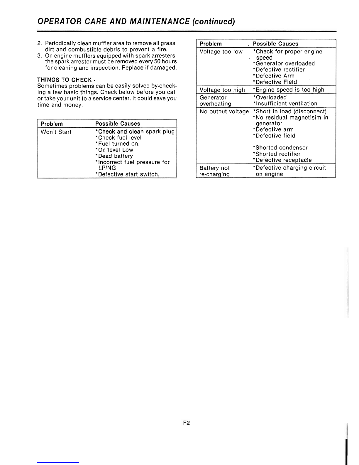
2.
Periodically clean muffler areato removeallgrass,
dirt and combustible debris to prevent a fire.
3.
On engine mufflersequipped with spark arresters,
the spark arrester must beremovedevery 50 hours
for cleaning and inspection. Replace if damaged.
THINGS TO CHECK
-
Sometimes problems can be easily solved by-check-
ing a few basic things. Check below before you call
or take your unit toaservice center. It could save you
time and money.
Problem Possible Causes
Won't Start 'Check and clean spark plug
*Check fuel level
*Fuel turned on.
*Oil'level Low
'Dead battery
*Incorrect fuel pressure for
LPlNG
'Defective start switch.
Problem
.
Possible Causes
Voltage too low 'Check for proper engine
.
speed
*Generator overloaded
*Defective rectifier
'Defective Arm
*Defective Field
.
Voltage too high *Engine speed is too high
Generator Overloaded
overheating *Insufficient ventilation
No output voltage *Short in load (disconnect)
*No residual magnetisim in
generator
'Defective arm
'Defective field
.
.
*Shorted condenser
'Shorted rectifier
'Defective receptacle
Battery not *Defective charging circuit
re-charging on engine

I
Remove
1
EXCITATION
WI.NDING
(STATOR)
FIELD
COILS
(ROTOR)
CAPACITOR
I
EXCITATION
RECTIFIERS
s$
MAIN
STATOR
for
.isolated
AC WINDING
\
CIRCUIT
bb
mC)FAYFC)
I
I.
I
GROUND
TF450016000 SCHEMATIC WIRING DIAGRAM

LIMITED
WARRANTY
r normal use and service.
There isnoother express warranty. To the extent permittedby law,
any andallwarranties, includingthose of merchantabilityandfitness
for a particular purpose, are limited to one year from date of ship-
ment, and liability for incidental or consequential damages or ex-
exclusion or limitationof incidental or consequentialdamages, so
the above limitation or exclusion may not apply to you. This war-
vary from state to state.
ENERGX
does not warrant engines or certain other component parts
of the product since such items are warranted by their manufacturers.
ENERGX
does not warrant
alterations or repairs
which were not
made by the
ENERGX
factory or a factory-authorized service sta-
tion and which affect the stability or reliability of the product.
ENERGX
does not warrant products which have been exposed to
misuse
andlor
negligence
or have been involved in an
accident.
ENERGX
reserves the
right to change or improve
its products
without incurring any obligations to make such changes or im-
provements on products purchased previously.
CAJEDE
W
-
---
----
-----
-----
-
-
-
-
-
-
-
-
-
--
-
---
-
CORPORATION
225
South
Cordova Avenue
Le Center,
MN
56057
(612)357-6821
PRINTED
IN
US.4
3/89
TF4500E/L. TF6000E/L
P/N
60707-023
t
I
This manual suits for next models
1
Popular Inverter manuals by other brands


Delta
Delta RPI M6A Quick installation guide

Go Power
Go Power GP-DC-KIT2 owner's manual

Qcells
Qcells Q.HOME PLUS ESS-G1 3.6 user manual

CanadianSolar
CanadianSolar CSI-50KTL-GS-FLB Installation and operation manual

AlcaPower
AlcaPower IRP3000D-12 user manual

Tripp Lite
Tripp Lite EMS1012UL Features & specifications

KEBCO
KEBCO COMBIVERT F5 instruction manual

Qcells
Qcells Q.PEAK DUO XL-G10 BFG Series Installation and operation manual

KEBCO
KEBCO COMBIVERT F5 INSTALLATION GUIDELINE

OutBack Power
OutBack Power FLEXpower ONE VFX3524 installation manual

MQ Power
MQ Power EGC-500C Specifications

FRONIUS
FRONIUS Primo 3.8-1 208-240 operating instructions