ENERGY KINETICS Smart Solar EWRA1 User manual

Solar Water Heating Appliance
Installation Manual
Pre-Heat Appliance
1, 2, 3 & 4-Collector Pre-heat Appliances
(EWRA1, EWRA2, EWRA3, EWRA4)
1, 2, 3 & 4-Collector Pre-heat Appliances
(EWRA1-DWHX, EWRA2-DWHX, EWRA3-DWHX, EWRA4-DWHX)
Energy Kinetics Inc.
51 Molasses Hill Road
Lebanon, NJ 08833
Tel: (908) 735-2066
Toll-free: 1-800-323-2066
Fax: (908) 735-2068
www.energykinetics.com
EnerWorks Inc
969 Juliana Drive
Woodstock, ON N4V 1C1
Canada
Tel: (519) 268-6500
Fax: (519) 268-6292
www.enerworks.com

EnerWorks Solar Water Heating Appliance
Installation Manual / Energy Kinetics Inc. - Page 2- © 2011 EnerWorks Inc.
Recognize this symbol as an indication of important safety information!
EnerWorks Residential Solar Water Heating Appliances must be installed as
directed by this manual by an EnerWorks authorized dealer or warranty is void.
CALIFORNIA PROPOSITION 65 WARNING: This product contains chemicals known to the
State of California to cause cancer, birth defects or other reproductive harm.

EnerWorks Solar Water Heating Appliance
© 2011 EnerWorks Inc. - Page 3- Energy Kinetics Inc. / Installation Manual
Foreword
Use this installation manual to install EnerWorks Pre-Heat Solar Water Heating Appliances
(product codes EWRA1, EWRA2, EWRA3 and EWRA4). This manual complements installation
training available through EnerWorks or approved distributors. EnerWorks training is mandatory
to become an EnerWorks authorized dealer.
EnerWorks encourages installers of EnerWorks products to always keep workmanship, best
practices and safety in mind. An organized installation will benefit both installer and end-user.
The EnerWorks Solar Collector is one of the highest rated in North America. This assessment
was carried out by third-party testing under the supervision and scrutiny of the Solar Rating and
Certification Corporation (SRCC). The EnerWorks Solar Collector has SRCC OG-100
certification and the EnerWorks Residential Solar Water Heating Appliances are certified to OG-
300 standards. This certification does not imply endorsement or warranty of these products by
SRCC.
The EnerWorks Pre-Heat Appliance is certified by the International Association of Plumbing and
Mechanical Officials (IAPMO) as meeting the standards of the Uniform Solar Energy Code
(USEC®). This certification does not imply endorsement or warranty by IAPMO.
The Pre-Heat Appliance described in this manual, when properly installed and maintained,
meets or exceeds the standards established by the Florida Solar Energy Center (FSEC), in
accordance with Section 377.705, Florida Statutes. This certification does not imply
endorsement or warranty of this product by the Florida Solar Energy Center or the State of
Florida.
The EnerWorks Pre-Heat Appliance is the first system in North America to achieve the
Canadian Standards Association (CSA) certification (CSA F379.1). This certification does not
imply endorsement or warranty by CSA.
EnerWorks Solar Water Heating Appliance
Installation Manual / Energy Kinetics Inc. - Page 4- © 2011 EnerWorks Inc.
Appliance must only be installed by an EnerWorks authorized installer or warranty
is void.
Recognize this symbol as an indication of important safety information!
EnerWorks Residential Solar Water Heating Appliances must be installed as
directed by this manual by an EnerWorks authorized dealer or warranty is void.
Before proceeding with installation of the EnerWorks Solar Water Heating
Appliance, make note of Energy Station and Solar Collector serial numbers on the
Product & Installation Registration Form included with the Owner Manual and in
the Appendices.
EnerWorks Solar Water Heating Appliance Installation Manuals:
Selection, Sizing and Site Evaluation
Collector Installation Manual
Pre-Heat Appliance Installation Manual
Single Tank Appliance Installation Manual (USA only)
Controller and Monitor Programming Guide
CARE, HANDLING & STORAGE
EnerWorks Solar Collectors are manufactured with tempered glass. Though
extremely resistant to impact, tempered glass can break if an edge is subjected to
stress. During storage and installation, protect glass edges. Glass breakage is not
covered by warranty.
Store collectors in a dry place, lying flat with glass up, or leaning on long edge with
glass facing out and connections at top. Protect collector from scratches and
damage by placing it on a soft surface such as a blanket or cardboard. When
hoisting collectors to roof, be very careful not to bang glass edge. Collectors must
not be levered over ladder or eave or they may be damaged. Be very careful of
collector connections as they are soft copper and may be easily damaged. A leak-
proof heat transfer fluid loop can only be achieved if collector connections are not
damaged.
Do not store collectors outside with glass face down. Due to EnerWorks’ patented
stagnation-control device, back of collector is not sealed to atmosphere. Rain may
enter collector if it is stored face down. Any damage due to ingress of rain is not
covered by warranty.
It is best to store both the EnerWorks Solar Collectors and the EnerWorks Energy
Station in a cool, dry place.

EnerWorks Solar Water Heating Appliance
© 2011 EnerWorks Inc. - Page 5- Energy Kinetics Inc. / Installation Manual
Contents
1 – Safety .........................................................................................................................7
2 – EnerWorks Pre-Heat Solar Water Heating Appliance.............................................8
2.1 Appliance description..........................................................................................8
2.2 Appliance schematic ...........................................................................................9
2.3 Appliance selection and sizing.........................................................................10
2.4 Solar storage tank considerations ...................................................................10
3 – Recommended Work Sequence.............................................................................12
4 – Pre-Heat Appliance Installation..............................................................................14
4.1 Energy Station schematic .................................................................................14
4.2 Energy Station installation................................................................................16
4.3 Thermosiphon loop installation........................................................................19
4.4 Water connections – bypass valves.................................................................23
4.5 Water connections – cold mains supply..........................................................25
4.6 Water connections – solar storage hot outlet .................................................26
4.7 Water connection to hot water distribution network ......................................26
4.8 Filling tanks with water......................................................................................27
4.9 Appliance heat transfer fluid line-set connections .........................................27
4.10 Controller connections....................................................................................29
4.11 Appliance control wire connections................................................................31
5 – Charging Appliance ................................................................................................33
5.1 Leak testing with air...........................................................................................33
5.2 Preparation of heat transfer fluid......................................................................34
5.3 Charging Appliance with heat transfer fluid....................................................34
6 – Collector Flashing and Leaf guard Installation.....................................................37
6.1 Side flashing for 1-collector Appliances..........................................................39

EnerWorks Solar Water Heating Appliance
Installation Manual / Energy Kinetics Inc. - Page 6- © 2011 EnerWorks Inc.
6.2 Center-flashing for 2, 3 and 4-collector Appliances........................................39
6.3 Leaf guard installation.......................................................................................40
7 - Appliance Start-Up...................................................................................................41
8 - Final Steps................................................................................................................42
9 - Scheduled Maintenance ..........................................................................................42
10 - Troubleshooting.....................................................................................................43
10.1 Controller..........................................................................................................43
10.2 Thermistor ........................................................................................................43
10.3 Pump .................................................................................................................44
10.4 Noisy pump ......................................................................................................45
10.5 Heat transfer fluid pressure drop ...................................................................45
Exploded Views.........................................................................................................46
Controller operation..................................................................................................49
Product & Installation Registration Form ...............................................................52
Maintenance Log.......................................................................................................53
Residential Site Survey ............................................................................................54
Tool and Supply Checklist .......................................................................................56
EnerWorks Solar Water Heating Appliance
© 2011 EnerWorks Inc. - Page 7- Energy Kinetics Inc. / Installation Manual
1 – Safety
EnerWorks assumes no responsibility for damage, loss or injury related to
installation of this appliance.
Observe any and all regulations relating to installation of solar appliances and to
plumbing to potable water supply. Plumbing and/or building permits may be
necessary. EnerWorks residential Water Heating Appliances utilize a single-wall or
double wall heat exchangers. Single-wall heat exchangers may not be acceptable
in all jurisdictions. Back flow prevention device or assembly may be required on
water supply to home or upstream from solar water heater.
Ensure that power or gas supply and water supply to existing water heater and to
EnerWorks Solar Water Heating Appliance are off during the installation.
Do not modify any electrical connections in the EnerWorks Energy Station.
Cover on Energy Station is designed to protect components from damage, and to
protect users from injury. Do not operate with Energy Station cover removed.
Assemblies and materials used during installation shall meet requirements of
local, regional, state, provincial, and federal regulations and fire codes. Any
penetrations made in drywall or any other firewall must be fixed to maintain
integrity of fire protection.
Use of heat transfer fluid other than a 50/50 mix by volume of Propylene Glycol
USP and distilled or de-mineralized water is not permitted. Use of any heat
transfer fluid other than that specified by appliance manufacturer will void
warranty, and may result in poor performance, equipment damage, and risk to
health and safety.
All persons working on roofs should have successfully completed a fall-safety
course and should be properly equipped with appropriate safety equipment.

EnerWorks Solar Water Heating Appliance
Installation Manual / Energy Kinetics Inc. - Page 8- © 2011 EnerWorks Inc.
2 – EnerWorks Pre-Heat Solar Water Heating Appliance
2.1 Appliance description
The EnerWorks Solar Water Heating Appliance has four main parts (Fig.2.2) – the solar
collectors, the line-set, the Energy Station and the solar storage tank.
The Energy Station uses a pump to circulate a heat transfer fluid through the “collector loop”.
This collector loop includes the solar collectors, the fluid lines or “line-set” and a heat-
exchanger. The collector loop is a “closed loop”, meaning there is no contact of the heat transfer
fluid with your potable water or with the atmosphere. The collector loop contains only a small
volume of heat transfer fluid which is food-grade and freeze-protected. Though freeze-protection
may not be necessary in all areas, the heat transfer fluid also has an elevated boiling point and
so is suitable throughout North America.
When exposed to sunlight, the solar collectors get hot. As the heat transfer fluid passes through
the collectors, it absorbs heat and then travels down the line-set to the Energy Station. The hot
fluid passes through the heat-exchanger and heat is transferred to the potable water. After
giving up its heat to the potable water, the cool heat transfer fluid is pumped back to the solar
collectors to be heated again. Hot potable water is stored in the solar storage tank.
In the Pre-Heat Solar Water Heating Appliance (
Fig.2.2), the solar storage tank is a standard
North American electric hot-water tank. No power is connected to this tank – it only stores solar-
heated water. The solar storage tank is plumbed in series with the original water heater (electric
or fossil fuel). Whenever hot water is used in the home, solar-heated water leaves the solar
storage tank and enters the original water heater. The original water heater now requires much
less energy for water heating.
Thus, the Appliance displaces energy, but it does not replace the original water heater. The
original heater guarantees hot water even under poor solar conditions (at night or when very
cloudy). It also ensures that hot water is stored or supplied at an appropriate temperature to kill
harmful bacteria. The acceptable temperature set point is specified in local plumbing codes. Do
not turn off or bypass the back-up water heater. Even in summer months, additional heat from
the back-up heater may be required.
For more information on Appliance components and function, please see the Owner Manual.
EnerWorks Solar Water Heating Appliance
© 2011 EnerWorks Inc. - Page 9- Energy Kinetics Inc. / Installation Manual
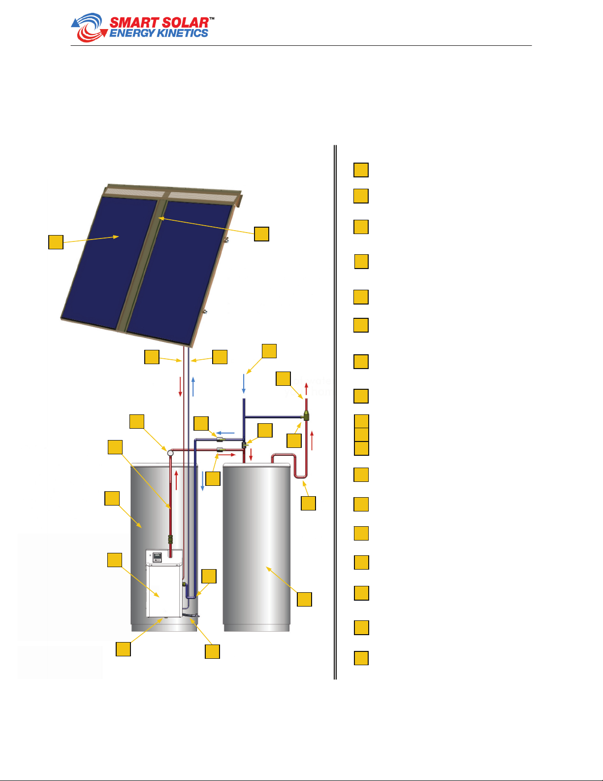
2.2 Appliance schematic
Solar collectors (1 to 4)
Line-set roof-penetration (behind flashing)
Heat transfer fluid line from collectors to
Energy Station (red – carries hot fluid)
Heat transfer fluid line from Energy Station to
collectors (blue – carries cool fluid)
Cold mains water supply (blue)
Hot water supply to home (red)
Thermosiphon loop,
solar-heated water to storage tank (red)
Thermometer
Bypass valves
(to isolate Appliance for service)
Anti-scald valve
(not included, may be required by code)
Solar storage tank
Heat trap (U-bend limits heat loss)
Energy Station
Pre-existing or auxiliary hot water tank or on-
demand heater
Pressure relief valve (inside cover)
Thermosiphon loop feed (from storage)
1
2
3
4
5
6
7
8
12
15
16
17
18
13
9
10
11
14
10
12
11
9
1
2
3 4 5
6
8
7
13
15
14
14
16
18
17
Fig.2.2 – EnerWorks Pre-Heat Solar Water Heating Appliance (with optional leaf-guard).

EnerWorks Solar Water Heating Appliance
Installation Manual / Energy Kinetics Inc. - Page 10 - © 2011 EnerWorks Inc.
2.3 Appliance selection and sizing
To achieve good performance and a good return on investment, Appliance must be sized
correctly and it must be oriented properly. Site evaluation is necessary to determine whether a
site is appropriate and to evaluate complexity of installation. It is also necessary to determine hot
water load, number of individuals in home, number of collectors and size of solar storage tank
(see Site Evaluation, Appliance Selection and Sizing).
A site survey (see Appendix – Residential Site Survey) has been developed to assist installers in
evaluating potential installation locations. This can be removed from Appendices and copied as
needed. Other tools such as the EnerWorks software, SolSimTM, and Solar Pathfinder are
recommended in determining best location and orientation of solar collectors. SolSimTM and its
user guide are available to EnerWorks authorized dealers.
The EnerWorks Pre-Heat Solar Water Heating Appliance is a pre-heat system (often referred to
as a two-tank system). It is installed to pre-heat water that enters existing water heater (electric
or fossil fuel hot-water tank, or on-demand water heater). When hot water is needed in home,
solar-heated water from solar storage tank enters existing water heater. Existing water heater
thus requires less energy. The pre-heat EnerWorks Pre-Heat Solar Water Heating Appliance
provides exceptional performance due to additional hot water storage capacity.
Solar storage tank size does not depend on size of existing water heater but on number of solar
collectors. Number of collectors depends on hot water use and on number of individuals in home.
Solar storage tank must be certified by a nationally recognized standard (e.g. UL or CSA).
2.4 Solar storage tank considerations
2.4.1 Line-set
Line-set carries heat transfer fluid from collectors to Energy Station and back again. Line-set
must be flexible, refrigeration-grade 3/8” soft-copper tube. A proper and dedicated bending tool
must be used for tight bends. Line should be as smooth as possible with no unnecessary fittings
or bends. Site evaluation should include examining location and difficulty of roof and wall
penetrations. Appropriate techniques and materials for sealing penetrations are necessary.
New homes may choose to run line-set prior to closing in walls, or alternatively, running a 3”
chase from attic to mechanical room for later use. A line-set inside building may be shorter and
will lose less heat. Outside line-sets must be covered as insulation is not UV-stable. Line-set may
be covered by a false downspout that matches siding or existing eavestrough, or through
electrical conduit. Installer should consult homeowner regarding aesthetics and complexity of
installation.
2.4.2 Heat trap nipple or gasket must be removed
Some water heater tanks have a heat trap valve, gasket or flapper in hot-outlet nipple. Hot water
is less dense and more buoyant than cold and tends to migrate up and out of storage tanks.
Denser cool water from household pipes tends to sink into storage tanks. Tank manufacturers
install heat trap valve, gasket or flapper to limit this convective flow and associated heat losses
(Fig.2.4.2.1).

EnerWorks Solar Water Heating Appliance
© 2011 EnerWorks Inc. - Page 11 - Energy Kinetics Inc. / Installation
Manual
Heat trap device must be removed to allow solar-heated water to enter hot-
outlet port. If heat trap device is not removed, solar energy cannot be
captured and stored. Not removing heat trap device may lead to degradation
of heat transfer fluid and to damage of Appliance. Damage to heat transfer
fluid or to Appliance due to heat trap device not being removed is not
covered by warranty.
Once heat trap device is removed, a standard 2½” or 3” x ¾” - MNPT brass or di-electric nipple
with appropriate thread sealant must be threaded into hot-outlet.
2.4.3 Tank size
If a home requires hot water regularly throughout the day, the minimum solar storage tank size
(see Selection, Sizing and Site Evaluation guide) is a good solution, providing good value and
taking up a minimum of space.
If a home’s hot water use is concentrated at the beginning and at the end of the day, a solar
storage tank larger than the minimum required size will provide greater storage capacity of hot
water and better performance.
A smaller family may benefit from a larger tank. With less hot-water use, more storage may limit
the occurrence of stagnation and maximize daily energy gain.
2.4.4 Space requirements
Energy Station and solar storage tank will be located in mechanical or utility room. Stairway and
doorway clearance must be examined. Additional floor space is required for solar storage tank
and Energy Station. Consideration must be given to location and complexity of wall and ceiling
penetrations, and to plumbing of Appliance to water distribution network.
Allow sufficient space around solar storage tank for installation and maintenance procedures.
Space may be required for a 2 gal US (7.8 L) expansion tank to be mounted on side of solar
storage tank or on wall (4.9.2 Supplemental expansion tank).
Heat trap nipple in hot-
outlet of water heater tank
must be removed
If not removed, ball would
prevent solar-heated water
from entering tank
Fig.2.4.2.1 – Heat trap nipple or gasket must be removed from solar storage tank.

EnerWorks Solar Water Heating Appliance
Installation Manual / Energy Kinetics Inc. - Page 12 - © 2011 EnerWorks Inc.
Follow tank manufacturer’s instructions and all electrical, building, fire and
plumbing codes regarding placement and installation of hot-water tanks.
2.4.5 AC power required
EnerWorks Energy Station requires 120 VAC and should be installed in proximity to a 120 VAC
electrical outlet. Total draw from Energy Station is approximately 23 W.
Surge protection is recommended as any damage to Energy Station components due to power
surge is not covered by warranty.
A licensed electrician may be required to make electrical connections. Follow all
codes and regulations.
Follow tank manufacturer’s instructions and all electrical, building, fire and
plumbing codes regarding placement and installation of hot-water tanks.
2.4.6 Drain Pan
Tank should be placed in an area that will prevent damage to floors, ceilings, and furniture in the
event of a leak. If this is not possible, a drain pan must be installed under water heater. Pan must
have a pipe to a drain or other outlet for water.
Follow all code requirements regarding drain pans, proximity to drain and draining
procedures.
2.4.7 Minimizing heat loss, maximizing performance
Improved performance and value for homeowner can be achieved by installing a better insulated
tank or a lifetime-warranty tank. A tank wrap or blanket on both solar storage and on pre-existing
water heater tank will minimize heat loss and improve performance.
Rigid foam board insulation placed under water heater tanks can further reduce heat loss. About
two inches of extruded polystyrene (XPS) board is recommended as it resists compression and
does not absorb water.
All piping, hot and cold, should be insulated to limit heat loss and to limit condensation.
3 – Recommended Work Sequence
Power or gas supply to existing water heater is turned off; tank is drained as required.
Solar storage tank is positioned.

EnerWorks Solar Water Heating Appliance
© 2011 EnerWorks Inc. - Page 13 - Energy Kinetics Inc. / Installation
Manual
Energy Station is mounted to solar storage tank and thermosiphon loop connections are
completed.
Mains water connections are completed. Hot outlet and anti-scald valve (if applicable –
highly recommended) connections to home hot-water distribution network are completed.
Source and Storage wires are connected to Controller.
Tanks are filled with water and purged of air. Power or gas supply to pre-existing water
heater may be turned back on.
Collector(s) are installed are per Collectors Installation Manuals.
Line-set is connected to Energy Station. Collector loop is leak tested, charged with heat
transfer fluid and purged of air.
Fittings are insulated and collector flashing is installed.
Controller and Monitor are programmed and Appliance is commissioned.
Installer discusses Appliance operation and maintenance with homeowner and completes
and submits Product & Installation Registration Form included with Owner Manual and in
Appendices.
It may be possible to mount Energy Station to solar storage tank and to complete thermosiphon
loop connections prior to on-site installation. Energy Station may be installed to top-feed or to
bottom-feed storage tank.
Before proceeding with installation of EnerWorks Energy Station, make note of
serial numbers (Fig.3.1) on Product & Installation Registration Form included with
Owner Manual and in Appendices. Serial numbers are required for warranty
service.
Fig.3.1 – Energy Station Label.
Serial number

EnerWorks Solar Water Heating Appliance
Installation Manual / Energy Kinetics Inc. - Page 14 - © 2011 EnerWorks Inc.
4 – Pre-Heat Appliance Installation
4.1 Energy Station schematic
1 Over-temperature control wire 11 Lower manifold (behind pump assembly)
2 Differential Temperature Controller 12 Flexible corrugated water pipe, supply
from storage to Energy Station
3 Pressure gauge (0 – 60 psi) 13 Solar storage tank drain
4 Expansion tank 14 Heat-exchanger
5 Charging port, return from system to
reservoir 15 Heat trap
6 120 VAC, three-prong to grounded,
surge protected outlet 16 Upper manifold with anti-fouling valve
7 Heat transfer fluid pump (positive-
displacement gear pump) 17 Cold heat transfer fluid from heat-
exchanger to collector(s)
8 Pressure relief valve (50psi) 18 Hot heat transfer fluid from collector(s) to
heat-exchanger
9 Charging port, supply to system
from charging pump and reservoir 19 Cold (mains) water inlet
10 Heat transfer fluid filter (in lower
manifold) 20 Thermosiphon loop, hot water to storage
from Energy Station
Fig.4.1.1 – Energy Station mounted to solar storage tank.
2
3
4
7
8
5
9
10
11
12
14
15
17
16
20
19
18
13
1
6
EnerWorks Solar Water Heating Appliance
© 2011 EnerWorks Inc. - Page 15 - Energy Kinetics Inc. / Installation
Manual
Noise is to be anticipated from a pump with moving parts. Pump will operate during
daylight hours. Homeowner must be aware of anticipated noise and be involved in
determining best location for Appliance. Noise is not a manufacturing defect and
does not affect operation of Solar Water Heating Appliance.
Installation of EnerWorks Energy Station requires plumbing to domestic potable
water distribution network. A plumbing permit may be necessary. An anti-scald
valve may be necessary and is highly recommended. It is the responsibility of the
homeowner and of the installer to obtain any necessary permits and to follow all
applicable codes and regulations.
Connections to domestic potable water distribution network may have to be
performed by a licensed plumber. It is the responsibility of the homeowner and of
the installer to follow all applicable codes and regulations.
Electrical connections to Energy Station and to solar storage tank may have to be
done by a licensed electrician. Do not attempt unless fully qualified.
This installation may have to be inspected. Follow all codes and regulations.
EnerWorks assumes no liability for any damage to property or injury or death
resulting from improper installation or from modification of the EnerWorks Solar
Water Heating Appliance.
EnerWorks Appliance includes supplies and fittings specific to Energy Station
connections. Additional materials (copper or PEX and fittings) are required to
connect water mains to appliance and to connect appliance to hot-water
distribution network.
MNPT (Male National Pipe Thread), and FIP (Female Iron Pipe) connections all
require thread sealant or Teflon tape. Do not apply sealant or tape to the first
thread as it may contaminate water and clog taps and appliances. Do not apply
thread sealant or Teflon tape to Energy Station flare connections as it may
contaminate and damage the heat transfer fluid. Degradation of fluid and/or
damage to appliance due to contamination of fluid is not covered by warranty.
A back flow prevention device may need to be installed on water supply to home
and/or upstream of solar storage tank. Follow all codes and regulations.
Before installing the EnerWorks Energy Station, shut down power or gas to
existing hot-water heater and drain tank.

EnerWorks Solar Water Heating Appliance
Installation Manual / Energy Kinetics Inc. - Page 16 - © 2011 EnerWorks Inc.
4.2 Energy Station installation
1. Shut off power or fuel supply to existing water heater. Shut off water supply to existing water
heater. Drain tank as needed for top-feed connections, or drain fully for bottom-feed
connections.
2. Position solar storage tank. A drain pan may be desirable or required by code. Extruded
polystyrene board is recommended to insulate tank from floor. Ensure enough space is left
around tank for proper ventilation and access for maintenance.
If installing Energy Station on BOTTOM-FEED TANK ONLY, Energy Station will
block access to lower thermostat cover – lower thermostat connections must be
completed before Energy Station is mounted (see 4.10.1 Over-temperature control
connection).
3. [BOTTOM-FEED TANK ONLY] Remove lower thermostat cover plate from side of storage
tank. Remove insulation and/or plastic plate covering element/thermostat. Disconnect wires
from heating element – not from thermostat. Connect black wire descending from top to
vacant terminal of thermostat (Fig. 4.10.5). Set lower thermostat setting to 120 °F (50 °C)
(Fig.4.10.5). Carefully stow wires. Re-install insulation and cover plate to hide connections
(see 4.10.1 Over-temperature control connection).
4. [TOP-FEED TANK ONLY] Remove plastic dip tube from cold port (inlet) at top of tank
(optional). If no fitting is in cold port, apply thread sealant or Teflon tape to supplied ¾” MNPT
square-head brass plug. Thread plug into cold port at top of tank and tighten (5/8” open-
ended wrench, ¾” 12-point combination wrench or socket). If a ¾” MNPT nipple is already
installed in cold port, it may be removed or simply capped with supplied ¾” FIP cap. (This
may be used as an air-bleed when tank is filled.)
5. [ALL TANKS] Check hot water port (outlet) at top of storage tank for anti-siphon or
heat trap valve, gasket or flapper. If present – remove it. If anti-siphon or heat trap
valve, gasket or flapper is not removed, solar-heated water will not enter storage and
Appliance will not function as designed. If ¾” MNPT nipple is damaged during
removal, replace with new 2½” x ¾” MNPT nipple.
6. Remove Energy Station from box. Unscrew Phillips screws that hold outer case to Energy
Station. Remove cover and set aside where it will not get damaged. Remove protective cap
from water port at right of lower manifold.
7. With Energy Station lying flat on floor or on work bench, connect and tighten flexible
corrugated copper pipe to water port at right of lower manifold (Fig.4.2.1). Thread sealant or
Teflon tape is not required as gasket ensures water-tight seal. Do not over-tighten or gasket
may be damaged.

EnerWorks Solar Water Heating Appliance
© 2011 EnerWorks Inc. - Page 17 - Energy Kinetics Inc. / Installation
Manual
Hose clamp
Expansion tank
Schrader valve
Pressure gauge
8. Storage tank temperature sensor, or thermistor, is taped to inside of Energy Station housing
at lower right and connected to Controller by two blue wires. Slide hose-clamp over
corrugated copper pipe and fasten thermistor to smooth surface of corrugated pipe, close to
manifold (Figs.4.2.2). Do not over-tighten as thermistor may dent and damage corrugated
pipe.
9. Using an accurate pressure
gauge, check expansion tank air
pressure. Blue cap must be
unscrewed from Schrader valve
before checking pressure
(Fig.4.2.3). Pressure should be 25
psi. Adjust as necessary (with a
bicycle pump or compressor, or
by releasing air from expansion
tank).
Fig.4.2.1 – Flexible pipe connected to Energy Station. Hose clamp ready to attach thermistor.
Thermist
or
Fig.4.2.2 – Thermistor clamped to corrugated
copper pipe close to lower manifold.

EnerWorks Solar Water Heating Appliance
Installation Manual / Energy Kinetics Inc. - Page 18 - © 2011 EnerWorks Inc.
Fig.4.2.3 – Expansion tank Schrader valve and pressure measurement
10. [TOP-FEED TANK ONLY] Remove drain valve from bottom port of tank. Apply thread
sealant or Teflon tape to both ends of supplied 2½” x ¾” MNPT nipple. Thread into bottom
port. Thread middle port of supplied ¾” FIP-FIP-MNPT street-tee onto nipple and tighten
such that MNPT points to front of tank where Energy Station will be mounted (Fig.4.2.4).
11. [TOP-FEED TANK ONLY] Apply thread sealant or Teflon tape to removed drain valve. If
plastic is damaged, a metal replacement is recommended. Thread into remaining FIP port of
street-tee and tighten (Fig.4.2.4).
12. With Energy Station upright (vertical) and corrugated copper pipe straight, thread un-
connected end of corrugated pipe onto MNPT port of street-tee on top-feed tank (Fig.4.2.4),
or directly to cold inlet port of bottom-feed tank (Fig.4.2.5). Tighten, but do not over-tighten as
gasket may be damaged.
Fig.4.2.5 – Direct connection for bottom-feed tank.
13. Lift Energy Station and “walk” it in to tank, such that Energy Station mounting brackets are in
contact with storage tank wall and corrugated copper pipe has smooth bend (Figs.4.2.6 &
4.2.7). Place Energy Station as lower as possible, keeping at least (1¾” (50mm) off floor).
Place it on block or on boot such that bottom of heat exchanger is higher than drain. This will
allow water to drain from Energy Station if storage tank is drained. It also ensures access for
charging and maintenance (e.g., cleaning of heat transfer fluid filter.)
Access to hex-cap on underside of lower manifold must be maintained for removal,
cleaning and re-insertion of heat transfer fluid filter. Energy Station must be at least
1¾” (50mm) off floor to allow for service. See, 9 – Scheduled Maintenance.
Drain removed from tank
and threaded into street-tee
Drain port of top-feed tank
¾” FIP-FIP-MNPT brass
street-tee
¾” MNPT nipple
Corrugated pipe feeds
water to Energy Station
Direct connection to cold inlet
Bottom-feed tank
Fig.4.2.4 – Top-feed tank connection includes ¾” MNPT nipple and street-tee.

EnerWorks Solar Water Heating Appliance
© 2011 EnerWorks Inc. - Page 19 - Energy Kinetics Inc. / Installation
Manual
14. Using one included ¼” hex-head self-drilling screw, secure one upper Energy Station
bracket to storage tank (¼” nut-driver, 6” magnetic extension recommended for electric
drill). Ensure Energy Station is level and secure opposite bracket to tank with another
self-drilling screw. Insert remaining self-drilling screws into brackets to secure Energy
Station to solar storage tank.
Regular maintenance of solar storage tank will include draining to remove
sediment (see tank manufacturer’s instructions). Ensure proper access to drain.
Modify street-tee orientation or replace with ¾” FIP tee and ¾” MNPT nipples if
necessary.
4.3 Thermosiphon loop installation
Thermosiphon loop must be copper pipe. Temperature rating of PEX tubing may be
exceeded and must not be used.
1. Visually inspect hot-outlet nipple for heat trap valve or gasket. Insert a screw driver into
hot-outlet to determine presence of heat trap valve or gasket. If a heat trap device is
present, remove it (see 2.4.1 Heat trap valve or gasket must be removed).
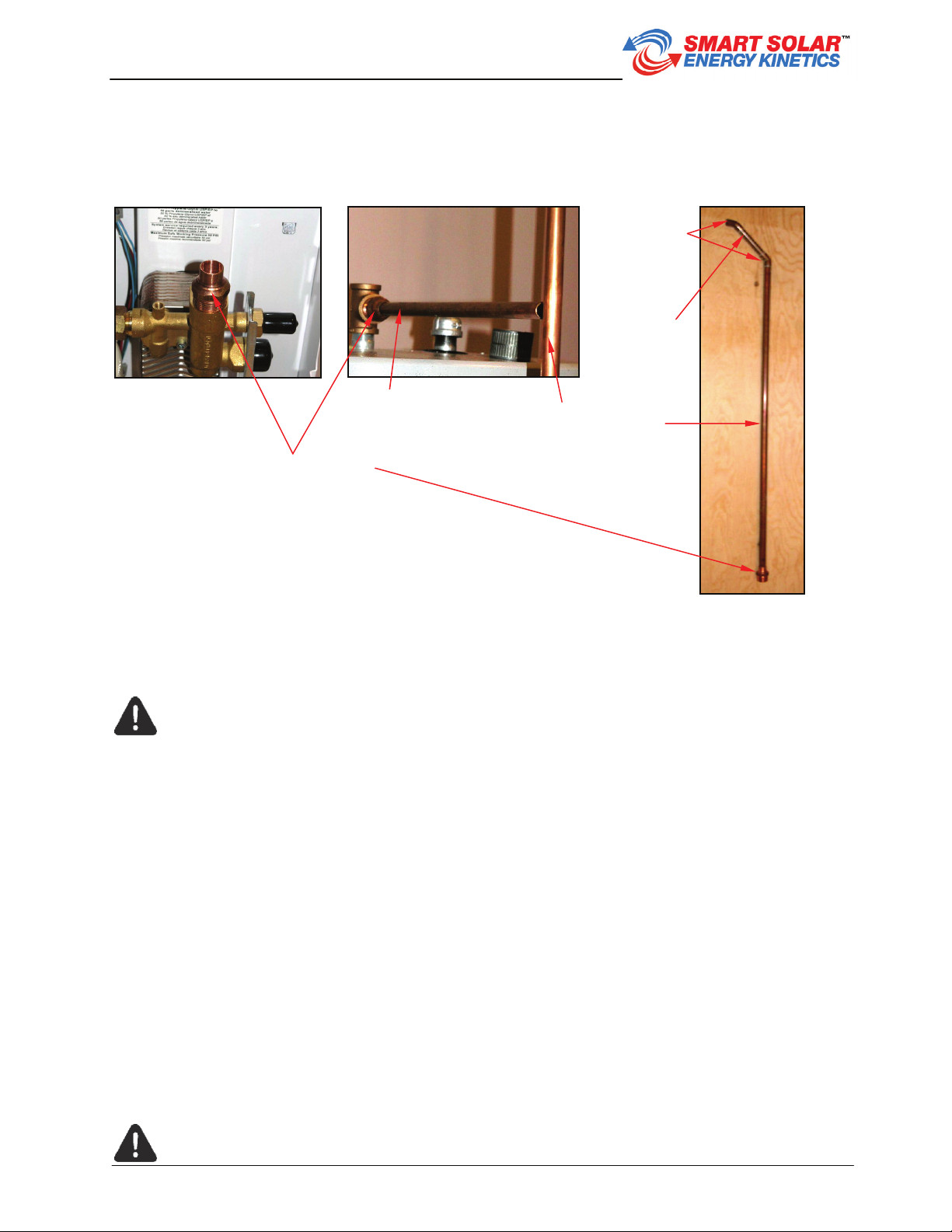
2. Apply thread sealant or Teflon tape to both ends of ¾” MNPT
nipple x 2½” and thread into hot-outlet port of solar storage
tank. If ¾” MNPT nipple without heat trap device is already
installed in hot-outlet port, apply thread sealant or Teflon tape.
3. Thread side port of supplied ¾” FIP brass tee to hot-outlet
nipple (Fig.4.3.1). Tighten such that middle port of brass tee
points in direction of soon-to-be installed thermosiphon loop (in
direction of water port at top of upper manifold of Energy
Station).
4. Remove protective plug from top port of upper manifold.
Loosely thread ¾” MNPT x ½” sweat fittings into ¾” FIP port at
Fig.4.3.1 – Brass tee connected to
top of solar storage tank
Fig.4.2.6– Positioning Energy Station. Fig.4.2.7 – Securing Energy Station.
EnerWorks Solar Water Heating Appliance
Installation Manual / Energy Kinetics Inc. - Page 20 - © 2011 EnerWorks Inc.
top of upper manifold and into middle port (horizontal) of hot port ¾” FIP brass tee (Fig.4.3.2).
5. Insert lengths of ½” rigid copper pipe into ½” sweat fittings in upper manifold and in brass tee
such that they meet at top edge of tank
Fig.4.3.2 – Thermosiphon loop – horizontal and angled sections and vertical riser.
TIP: Using flexible copper water tube (certified for domestic water use) may
facilitate installation. Do not solder tube into upper manifold fitting in place as hot
solder and flux may damage anti-fouling (back flush) valve. Solder unbent tube and
fitting first, and then install in upper manifold. Bend tube and solder into hot-outlet
fitting.
6. Thermosiphon loop requires two 45°elbow bends to facilitate natural convection. One 90°
elbow is not acceptable. Cut pipe lengths to accommodate two 45°elbow x ½” sweat fittings
with an angled pipe length between them. Thermosiphon loop will consist of vertical riser and
horizontal section with angled (45°) section in between (Fig. 4.3.2). Adjust orientation of hot
port ¾” FIP brass tee to ensure a thermosiphon riser is vertical.
7. Cut vertical thermosiphon riser and insert ½” sweat x ½” sweat union coupling (not included)
(remove small section of pipe if necessary). Union coupling will facilitate maintenance and/or
removal of Energy Station if necessary. Union coupling will facilitate dry fitting and should be
close to top of thermosiphon riser splitting it into an upper and a lower section.
8. With thermosiphon loop fitted, remove pipe, union coupling, 45°-elbow fittings and unthread,
¾” MNPT x ½” sweat fittings.
Anti-fouling back flush valve should be visible in top port of upper manifold. Back
flush valve is made of plastic. Damage to back flush valve may occur if hot solder
or flux drips down into valve – do not perform any soldering of copper in place
¾”-MNPT x ½”-sweat
Thermosiphon
horizontal section Thermosiphon
vertical riser
Angled
section
45°-elbow x
½”-sweat
fittings
This manual suits for next models
7
Table of contents
Popular Water Heater manuals by other brands

PVI
PVI MAXIM Specifications

Eccotemp
Eccotemp 40-H Use & care manual

GSW
GSW 710 Installation manual and owner's guide

iDM
iDM HYGIENIK 2.0 installation instructions

Joannes
Joannes CLIZIA D 32 AS Instructions for use & installation

Modine Manufacturing
Modine Manufacturing 1-500 Installation and service manual

BaltGaz
BaltGaz NEVALUX-5611 user manual

State Water Heaters
State Water Heaters SUF-100-250 instruction manual

Dux
Dux AIROHEAT D2FHG4HW0C Installation and owner's manual

Quietside
Quietside DPW-199C user manual

Candy
Candy CTR10RS/E instruction manual

Takagi
Takagi T?KJr2?IN Installation manual and owner's guide


