Joannes CLIZIA D 32 AS Technical manual

&
cod. 3541C820 — Rev. 00 - 09/2012
CLIZIA D 32 AS
68
89
cod.
010007X0
cod.
8.52289.0
75 117 77
677
49.5 76.5 54 51 79.5 75.5
D
E
F
A
B
C
ABCD FE
58.5
178
126
76 54 51 80.5 80
330
700
400
Ø
30
Ø
30
Ø
24.5
Ø
24.5
Ø
24.5
FABCD E
117
93 mm
114 mm
770 mm
791 mm
85 115 115 85
195
IT -
ISTRUZIONE PER L’USO L'INSTALLAZIONE E LA MANUTENZIONE
EN -
INSTRUCTIONS FOR USE, INSTALLATION AND MAINTENANCE
ES -
INSTRUCCIONES DE USO, INSTALACIÓN Y MANTENIMIENTO
RU -
ɊɍɄɈȼɈȾɋɌȼɈ ɉɈ ɗɄɋɉɅɍȺɌȺɐɂɂ, ɆɈɇɌȺɀɍ ɂɌȿɏɈȻɋɅɍɀɂȼȺɇɂɘ

CLIZIA D 32 AS
2IT cod. 3541C820 - Rev. 00 - 09/2012
IT
1. AVVERTENZE GENERALI
• Leggere ed osservare attentamente le avvertenze contenute in questo libretto di
istruzioni.
• Dopo l’installazione della caldaia, informare l’utilizzatore sul funzionamento e con-
segnargli il presente manuale che costituisce parte integrante ed essenziale del pro-
dotto e deve essere conservato con cura per ogni ulteriore consultazione.
• L’installazione e la manutenzione devono essere effettuate in ottemperanza alle
norme vigenti, secondo le istruzioni del costruttore e devono essere eseguite da
personale professionalmente qualificato. È vietato ogni intervento su organi di rego-
lazione sigillati.
• Un’errata installazione o una cattiva manutenzione possono causare danni a perso-
ne, animali o cose. È esclusa qualsiasi responsabilità del costruttore per i danni cau-
sati da errori nell’installazione e nell’uso e comunque per inosservanza delle
istruzioni.
• Prima di effettuare qualsiasi operazione di pulizia o di manutenzione, disinserire
l’apparecchio dalla rete di alimentazione agendo sull’interruttore dell’impianto e/o
attraverso gli appositi organi di intercettazione.
• In caso di guasto e/o cattivo funzionamento dell’apparecchio, disattivarlo, astenen-
dosi da qualsiasi tentativo di riparazione o di intervento diretto. Rivolgersi esclusiva-
mente a personale professionalmente qualificato. L’eventuale riparazione-
sostituzione dei prodotti dovrà essere effettuata solamente da personale professio-
nalmente qualificato utilizzando esclusivamente ricambi originali. Il mancato rispetto
di quanto sopra può compromettere la sicurezza dell’apparecchio.
• Questo apparecchio dovrà essere destinato solo all’uso per il quale è stato espres-
samente previsto. Ogni altro uso è da considerarsi improprio e quindi pericoloso.
• Gli elementi dell’imballaggio non devono essere lasciati alla portata di bambini in
quanto potenziali fonti di pericolo.
• L’apparecchio non è destinato ad essere usato da persone (bambini compresi) le
cui capacità fisiche, sensoriali o mentali siano ridotte, oppure con mancanza di
esperienza o di conoscenza, a meno che esse abbiano potuto beneficiare, attraver-
so l’intermediazione di una persona responsabile della loro sicurezza, di una sorve-
glianza o di istruzioni riguardanti l’uso dell’apparecchio.
• Lo smaltimento dell'apparecchio e dei suoi accessori deve essere effettuato in
modo adeguato, in conformità alle norme vigenti.
• Le immagini riportate nel presente manuale sono una rappresentazione semplifica-
ta del prodotto. In questa rappresentazione possono esserci lievi e non significative
differenze con il prodotto fornito.
2. ISTRUZIONI D’USO
2.1 Presentazione
CLIZIA D 32 AS è un generatore termico per riscaldamento e produzione di acqua calda
sanitaria ad alto rendimento funzionante a gas naturale, dotato di bruciatore atmosferico
ad accensione elettronica, camera stagna a ventilazione forzata, sistema di controllo a
microprocessore, destinata all’installazione in interno o esterno in luogo parzialmente
protetto (secondo EN 297/A6) per temperature fino a -5°C.
2.2 Pannello comandi
Pannello
fig. 1 - Pannello di controllo
Legenda pannello fig. 1
1Tasto decremento impostazione temperatura acqua calda sanitaria
2Tasto incremento impostazione temperatura acqua calda sanitaria
3Tasto decremento impostazione temperatura impianto riscaldamento
4Tasto incremento impostazione temperatura impianto riscaldamento
5Display
6Tasto Ripristino - selezione modalità Estate/Inverno- Menù “Temperatura Scor-
revole”
7Tasto selezione modalità Economy/Comfort - on/off apparecchio
8Simbolo acqua calda sanitaria
9Indicazione funzionamento sanitario
10 Indicazione modalità Estate
11 Indicazione multi-funzione
12 Indicazione modalità Eco (Economy)
13 Indicazione funzione riscaldamento
14 Simbolo riscaldamento
15 Indicazione bruciatore acceso e livello di potenza attuale (Lampeggiante du-
rante la funzione anomalia combustione)
16 Connessione Service Tool
17 Idrometro
Indicazione durante il funzionamento
Riscaldamento
La richiesta riscaldamento (generata da Termostato Ambiente o Cronocomando Remo-
to) è indicata dal lampeggio dell'aria calda sopra il radiatore sul display.
Il display (part. 11 - fig. 1) visualizza l’attuale temperatura della mandata riscaldamento
e durante il tempo di attesa riscaldamento la scritta “d2”.
Sanitario
La richiesta sanitario (generata dal prelievo d’acqua calda sanitaria) è indicata dal lam-
peggio dell'acqua calda sotto il rubinetto sul display.
Il display (part. 11 - fig. 1) visualizza l’attuale temperatura d’uscita dell’acqua calda sani-
taria e durante il tempo di attesa sanitario la scritta “d1“.
Comfort
La richiesta Comfort (ripristino della temperatura interna della caldaia), è indicata dal
lampeggio dell’acqua sotto il rubinetto sul display. Il display (part. 11 - fig. 1) visualizza
l’attuale temperatura dell’acqua contenuta in caldaia.
Anomalia
In caso di anomalia (vedi cap. 4.4) il display visualizza il codice di guasto (part. 11 - fig. 1)
e durante i tempi di attesa di sicurezza le scritte “d3” e “d4”.
2.3 Accensione e spegnimento
Collegamento alla rete elettrica
• Durante i primi 5 secondi il display visualizza la versione software della scheda.
• Aprire il rubinetto del gas a monte della caldaia.
• La caldaia è pronta per funzionare automaticamente ogni qualvolta si prelevi acqua
calda sanitaria o vi sia una richiesta riscaldamento (generata dal Termostato Am-
biente oppure dal Cronocomando Remoto).
Spegnimento e accensione caldaia
Premere il tasto on/off (part. 7 - fig. 1) per 5 secondi.
fig. 2 - Spegnimento caldaia
Quando la caldaia viene spenta, la scheda elettronica è ancora alimentata elettricamen-
te. È disabilitato il funzionamento sanitario e riscaldamento. Rimane attivo il sistema an-
tigelo. Per riaccendere la caldaia, premere nuovamente il tasto on/off (part. 7 fig. 1) per
5 secondi.
fig. 3
La caldaia sarà immediatamente pronta per funzionare ogni qualvolta si prelevi acqua
calda sanitaria o vi sia una richiesta riscaldamento (generata dal Termostato Ambiente
oppure dal Cronocomando Remoto).
BTogliendo alimentazione elettrica e/o gas all'apparecchio il sistema antigelo
non funziona. Per lunghe soste durante il periodo invernale, al fine di evitare
danni dovuti al gelo, è consigliabile scaricare tutta l’acqua della caldaia, quella
sanitaria e quella dell’impianto; oppure scaricare solo l’acqua sanitaria e intro-
durre l’apposito antigelo nell’impianto di riscaldamento, conforme a quanto pre-
scritto alla sez. 3.3.
2.4 Regolazioni
Commutazione Estate/Inverno
Premere il tasto estate/inverno (part. 6 - fig. 1) per 2 secondi.
Il display attiva il simbolo Estate (part. 10 - fig. 1): la caldaia erogherà solo acqua sani-
taria. Rimane attivo il sistema antigelo.
Per disattivare la modalità Estate, premere nuovamente il tasto estate/inverno (part. 6
- fig. 1) per 2 secondi.
Regolazione temperatura riscaldamento
Agire sui tasti riscaldamento (part. 3 e 4 - fig. 1) per variare la temperatura da un minimo
di 30°C ad un massimo di 80°C; si consiglia comunque di non far funzionare la caldaia
al di sotto dei 45°C.
fig. 4
0
1
4
2
3
reset
eco
comfort
915
13
12
11
8
1
36
7102
16414
5
17
I
I
I
I
I
I
I
I
I

CLIZIA D 32 AS
3
IT
cod. 3541C820 - Rev. 00 - 09/2012
&
Regolazione temperatura sanitario
Agire sui tasti sanitario (part. 1 e 2 - fig. 1) per variare la temperatura da un minimo di
40°C ad un massimo di 55°C.
fig. 5
Regolazione della temperatura ambiente (con termostato ambiente opzionale)
Impostare tramite il termostato ambiente la temperatura desiderata all’interno dei locali.
Nel caso non sia presente il termostato ambiente la caldaia provvede a mantenere l’im-
pianto alla temperatura di setpoint mandata impianto impostata.
Regolazione della temperatura ambiente (con cronocomando remoto opzionale)
Impostare tramite il cronocomando remoto la temperatura ambiente desiderata all’inter-
no dei locali. La caldaia regolerà l'acqua impianto in funzione della temperatura ambien-
te richiesta. Per quanto riguarda il funzionamento con cronocomando remoto, fare
riferimento al relativo manuale d'uso.
Selezione ECO/COMFORT
L’apparecchio è dotato di una funzione che assicura un’elevata velocità di erogazione di
acqua calda sanitaria e massimo comfort per l’utente. Quando il dispositivo è attivo (mo-
dalità COMFORT), l’acqua contenuta in caldaia viene mantenuta in temperatura, per-
mettendo quindi l’immediata disponibilità di acqua calda in uscita caldaia all’apertura del
rubinetto, evitando tempi di attesa.
Il dispositivo può essere disattivato dall’utente (modalità ECO) premendo, il tasto eco/
comfort (part. 7 - fig. 1). In modalità ECO il display attiva il simbolo ECO (part. 12 -
fig. 1). Per attivare la modalità COMFORT premere nuovamente il tasto eco/comfort
(part. 7 - fig. 1).
Temperatura scorrevole
Quando viene installata la sonda esterna (opzionale) il sistema di regolazione caldaia la-
vora con “Temperatura Scorrevole”. In questa modalità, la temperatura dell’impianto di
riscaldamento viene regolata a seconda delle condizioni climatiche esterne, in modo da
garantire un elevato comfort e risparmio energetico durante tutto il periodo dell’anno. In
particolare, all’aumentare della temperatura esterna viene diminuita la temperatura di
mandata impianto, a seconda di una determinata “curva di compensazione”.
Con regolazione a Temperatura Scorrevole, la temperatura impostata attraverso i tasti
riscaldamento (part. 3 - fig. 1) diviene la massima temperatura di mandata impianto. Si
consiglia di impostare al valore massimo per permettere al sistema di regolare in tutto il
campo utile di funzionamento.
La caldaia deve essere regolata in fase di installazione dal personale qualificato. Even-
tuali adattamenti possono essere comunque apportati dall’utente per il miglioramento
del comfort.
Curva di compensazione e spostamento delle curve
Premendo il tasto reset (part. 6 - fig. 1) per 5 secondi si accede al menù "Temperatura
scorrevole"; viene visualizzato "CU" lampeggiante.
Agire sui tasti sanitario (part. 1 - fig. 1) per regolare la curva desiderata da 1 a 10 secon-
do la caratteristica. Regolando la curva a 0, la regolazione a temperatura scorrevole ri-
sulta disabilitata.
Premendo i tasti riscaldamento (part. 3 - fig. 1) si accede allo spostamento parallelo delle
curve; viene visualizzato "OF" lampeggiante. Agire sui tasti sanitario (part. 1 - fig. 1) per
regolare lo spostamento parallelo delle curve secondo la caratteristica (fig. 6).
Premendo nuovamente il il tasto reset (part. 6 - fig. 1) per 5 secondi si esce dal menù
“Temperatura Scorrevole”.
Se la temperatura ambiente risulta inferiore al valore desiderato si consiglia di impostare
una curva di ordine superiore e viceversa. Procedere con incrementi o diminuzioni di una
unità e verificare il risultato in ambiente.
fig. 6 - Esempio di spostamento parallelo delle curve di compensazione
Regolazioni da Cronocomando Remoto
ASe alla caldaia è collegato il Cronocomando Remoto (opzionale), le regolazioni
descritte in precedenza vengono gestite secondo quanto riportato nella
tabella 1.
Tabella. 1
Regolazione pressione idraulica impianto
La pressione di caricamento ad impianto freddo, letta sull’idrometro caldaia (part. 17 -
fig. 1), deve essere di circa 1,0 bar. Se la pressione dell’impianto scende a valori inferiori
al minimo, la caldaia si arresta e il display visualizza l’anomalia F37. Agendo sul rubinet-
to di caricamento part. 1 fig. 7, riportarla al valore iniziale. A fine operazione richiudere
sempre il rubinetto di caricamento.
fig. 7 - Rubinetto di caricamento
3. INSTALLAZIONE
3.1 Disposizioni generali
L'INSTALLAZIONE DELLA CALDAIA DEVE ESSERE EFFETTUATA SOLTANTO DA
PERSONALE SPECIALIZZATO E DI SICURA QUALIFICAZIONE, OTTEMPERANDO A
TUTTE LE ISTRUZIONI RIPORTATE NEL PRESENTE MANUALE TECNICO, ALLE DI-
SPOSIZIONI DI LEGGE VIGENTI, ALLE PRESCRIZIONI DELLE NORME NAZIONALI
E LOCALI E SECONDO LE REGOLE DELLA BUONA TECNICA.
3.2 Luogo d’installazione
Il circuito di combustione dell’apparecchio è stagno rispetto l’ambiente di installazione e
quindi l’apparecchio può essere installato in qualunque locale. L’ambiente di installazio-
ne tuttavia deve essere sufficientemente ventilato per evitare che si creino condizioni di
pericolo in caso di, seppur piccole, perdite di gas. Questa norma di sicurezza è imposta
dalla Direttiva CEE n° 2009/142 per tutti gli apparecchi utilizzatori di gas, anche per quelli
cosiddetti a camera stagna.
L’apparecchio è idoneo al funzionamento in luogo parzialmente protetto secondo EN
297 pr A6, con temperatura minima di -5°C. Si consiglia di installare la caldaia sotto lo
spiovente di un tetto, all’interno di un balcone o in una nicchia riparata.
Il luogo di installazione deve comunque essere privo di polveri, oggetti o materiali infiam-
mabili o gas corrosivi.
La caldaia è predisposta per l’installazione pensile a muro ed è dotata di serie di una staf-
fa di aggancio. Fissare la staffa al muro secondo le quote riportate sul disegno in coper-
tina ed agganciarvi la caldaia. È disponibile a richiesta una dima metallica per tracciare
sul muro i punti di foratura. Il fissaggio alla parete deve garantire un sostegno stabile ed
efficace del generatore.
ASe l’apparecchio viene racchiuso entro mobili o montato affiancato lateralmen-
te, deve essere previsto lo spazio per lo smontaggio della mantellatura e per le
normali attività di manutenzione
I
I
I
I
I
I
I
I
I
20
30
40
50
60
70
80
90
85
20 10 0 -10 -20
1
2
3
4
5
6
8910 7
20 10 0 -10 -20
20
30
40
50
60
70
80
90
85
1
2
3
4
568910 7
OFFSET = 20 OFFSET = 40
Regolazione temperatura riscaldamento
La regolazione può essere eseguita sia dal menù del Cronoco-
mando Remoto sia dal pannello comandi caldaia.
Regolazione temperatura sanitario
La regolazione può essere eseguita sia dal menù del Cronoco-
mando Remoto sia dal pannello comandi caldaia.
Commutazione Estate/Inverno
La modalità Estate ha priorità su un'eventuale richiesta riscalda-
mento del Cronocomando Remoto.
Selezione Eco/Comfort
Disabilitando il sanitario dal menù del Cronocomando Remoto, la
caldaia seleziona la modalità Economy. In questa condizione, il
tasto
eco/comfort
(part. 7 - fig. 1) sul pannello caldaia, è disabili-
tato.
Abilitando il sanitario dal menù del Cronocomando Remoto, la cal-
daia seleziona la modalità Comfort. In questa condizione, con il
tasto
eco/comfort
(part. 7 - fig. 1) sul pannello caldaia, è possibile
selezionare una delle due modalità.
Temperatura Scorrevole
Sia il Cronocomando Remoto sia la scheda caldaia gestiscono la
regolazione a Temperatura Scorrevole: tra i due, ha priorità la
Temperatura Scorrevole della scheda caldaia.
1

CLIZIA D 32 AS
4IT cod. 3541C820 - Rev. 00 - 09/2012
3.3 Collegamenti idraulici
Avvertenze
B
Lo scarico della valvola di sicurezza deve essere collegato ad un imbuto o tubo di rac-
colta, per evitare lo sgorgo di acqua a terra in caso di sovrapressione nel circuito di ri-
scaldamento. In caso contrario, se la valvola di scarico dovesse intervenire allagando il
locale, il costruttore della caldaia non potrà essere ritenuto responsabile.
B
Prima di effettuare l’allacciamento, verificare che l’apparecchio sia predisposto per il
funzionamento con il tipo di combustibile disponibile ed effettuare una accurata pulizia
di tutte le tubature dell’impianto.
Effettuare gli allacciamenti ai corrispettivi attacchi secondo il disegno in copertina e ai simboli ri-
portati sull’apparecchio.
Nota:
l’apparecchio è dotato di by-pass interno nel circuito riscaldamento.
Caratteristiche dell’acqua impianto
In presenza di acqua con durezza superiore ai 25° Fr (1°F = 10ppm CaCO
3
), si prescrive l’uso di
acqua opportunamente trattata, al fine di evitare possibili incrostazioni in caldaia.
Sistema antigelo, liquidi antigelo, addittivi ed inibitori
Qualora si renda necessario, è consentito l’uso di liquidi antigelo, additivi e inibitori, solo ed esclu-
sivamente se il produttore di suddetti liquidi o additivi fornisce una garanzia che assicuri che i suoi
prodotti sono idonei all’uso e non arrecano danni allo scambiatore di caldaia o ad altri componenti
e/o materiali di caldaia ed impianto. È proibito l’uso di liquidi antingelo, additivi e inibitori generici,
non espressamente adatti all’uso in impianti termici e compatibili con i materiali di caldaia ed im-
pianto.
3.4 Collegamento gas
L’allacciamento gas deve essere effettuato all’attacco relativo (vedi figura in copertina) in confor-
mità alla normativa in vigore, con tubo metallico rigido oppure con tubo flessibile a parete continua
in acciaio inox, interponendo un rubinetto gas tra impianto e caldaia. Verificare che tutte le con-
nessioni gas siano a tenuta.
3.5 Collegamenti elettrici
Avvertenze
B
L’apparecchio deve essere collegato ad un efficace impianto di messa a terra eseguito
come previsto dalle vigenti norme di sicurezza. Far verificare da personale professional-
mente qualificato l’efficienza e l’adeguatezza dell’impianto di terra, il costruttore non è
responsabile per eventuali danni causati dalla mancanza di messa a terra dell’impianto.
La caldaia è precablata e dotata di cavo di allacciamento alla linea elettrica di tipo “Y”
sprovvisto di spina. I collegamenti alla rete devono essere eseguiti con allacciamento
fisso e dotati di un interruttore bipolare i cui contatti abbiano una apertura di almeno 3
mm, interponendo fusibili da 3A max tra caldaia e linea. E’ importante rispettare le po-
larità (LINEA: cavo marrone / NEUTRO: cavo blu / TERRA: cavo giallo-verde) negli al-
lacciamenti alla linea elettrica..
B
II cavo di alimentazione dell’apparecchio non deve essere sostituito dall’utente. In caso
di danneggiamento del cavo, spegnere l’apparecchio e, per la sua sostituzione, rivolger-
si esclusivamente a personale professionalmente qualificato. In caso di sostituzione, uti-
lizzare esclusivamente cavo
“HAR H05 VV-F”
3x0,75 mm2 con diametro esterno
massimo di 8 mm.
Termostato ambiente (opzional)
B
ATTENZIONE: IL TERMOSTATO AMBIENTE DEVE ESSERE A CONTATTI PULITI.
COLLEGANDO 230 V. AI MORSETTI DEL TERMOSTATO AMBIENTE SI DANNEG-
GIA IRRIMEDIABILMENTE LA SCHEDA ELETTRONICA.
Nel collegare cronocomandi o timer, evitare di prendere l'alimentazione di questi dispo-
sitivi dai loro contatti di interruzione. La loro alimentazione deve essere effettuata tramite
collegamento diretto dalla rete o tramite pile, a seconda del tipo di dispositivo.
Accesso alla morsettiera elettrica
Dopo aver tolto il mantello è possibile accedere alla morsettiera elettrica. La disposizione dei mor-
setti per i diversi allacciamenti è riportata anche nello schema elettrico alla
fig. 24
.
fig. 8 - Accesso alla morsettiera
3.6 Condotti fumi
Avvertenze
L’apparecchio è di “tipo C” a camera stagna e tiraggio forzato, l’ingresso aria e l’uscita
fumi devono essere collegati ad uno dei sistemi di evacuazione/aspirazione indicati di
seguito. L'apparecchio è omologato per il funzionamento con tutte le configurazioni ca-
mini Cny riportate nella targhetta dati tecnici. È possibile tuttavia che alcune configura-
zioni siano espressamente limitate o non consentite da leggi, norme o regolamenti locali.
Prima di procedere con l’installazione verificare e rispettare scrupolosamente le prescri-
zioni in oggetto. Rispettare inoltre le disposizioni inerenti il posizionamento dei terminali
a parete e/o tetto e le distanze minime da finestre, pareti, aperture di aerazione, ecc.
Diaframmi
Per il funzionamento della caldaia è necessario montare i diaframmi forniti con l’appa-
recchio. Verificare che in caldaia vi sia il corretto diaframma (quando questo sia da uti-
lizzare) e che esso sia correttamente posizionato.
ASostituzione diaframma con caldaia non installata
BSostituzione diaframma con caldaia e condotti fumo già installati
123456
72
139
138
34
A
1
2
B
3
2
1
4
5
6

CLIZIA D 32 AS
5
IT
cod. 3541C820 - Rev. 00 - 09/2012
Collegamento con tubi coassiali
fig. 9 - Esempi di collegamento con tubi coassiali ( = Aria / = Fumi)
Tabella. 2 - Tipologia
Per il collegamento coassiale montare sull'apparecchio uno dei seguenti accessori di
partenza. Per le quote di foratura a muro riferirsi alla figura in copertina.
Tabella. 3 - Accessori di partenza per condotti coassiali
Tabella. 4 - Diaframmi per condotti coassiali
Collegamento con tubi separati
fig. 14 - Esempi di collegamento con tubi separati ( = Aria / = Fumi)
Tabella. 5 - Tipologia
Per il collegamento dei condotti separati montare sull'apparecchio il seguente accesso-
rio di partenza:
fig. 15 - Accessorio di partenza per condotti separati
Prima di procedere con l’installazione, verificare il diaframma da utilizzare e che non sia
superata la massima lunghezza consentita tramite un semplice calcolo:
1. Definire completamente lo schema del sistema di camini sdoppiati, inclusi accessori
e terminali di uscita.
2. Consultare la tabella 7 ed individuare le perdite in meq (metri equivalenti) di ogni
componente, a seconda della posizione di installazione.
3. Verificare che la somma totale delle perdite sia inferiore o uguale alla massima lun-
ghezza consentita in tabella 6.
Tabella. 6 - Diaframmi per condotti separati
Tipo Descrizione
C1X
Aspirazione e scarico orizzontale a parete
C3X
Aspirazione e scarico verticale a tetto
Cod. 010006X0 - 08522870
fig. 10
Cod. 010008X0 - 08522880
fig. 11
Cod. 010007X0
fig. 12
Cod. 08522890
fig. 13
Coassiale 60/100 Coassiale 80/125
Massima lunghezza consentita 5 m 10 m
Fattore di riduzione curva 90° 1 m 0.5 m
Fattore di riduzione curva 45° 0.5 m 0.25 m
Diaframma da utilizzare
0 ÷ 2 m Ø 45 0 ÷ 3 m Ø 45
2 ÷ 5 m no diaframma 3 ÷ 10 m no diaframma
C
1X
C
1X
C
3X
C
3X
C
3X
C
1X
Ø
100
Ø
60
45.6
Ø126
Ø82
Ø60
Ø130
100
118
Ø
100
Ø
60
68
20
26 89
118
Ø
100
Ø
60
Ø
100
Ø
60
Tipo Descrizione
C1X
Aspirazione e scarico orizzontale a parete. I terminali di ingresso/uscita devono essere o concentrici o
abbastanza vicini da essere sottoposti a condizioni di vento simili (entro 50 cm)
C3X
Aspirazione e scarico verticale a tetto. Terminali di ingresso/uscita come per C12
C5X
Aspirazione e scarico separati a parete o a tetto e comunque in zone a pressioni diverse. Lo scarico e
l’aspirazione non devono essere posizionati su pareti opposte
C6X
Aspirazione e scarico con tubi certificati separatamente (EN 1856/1)
B2X
Aspirazione dal locale di installazione e scarico a parete o tetto
IMPORTANTE - IL LOCALE DEVE ESSERE DOTATO DI VENTILAZIONE APPROPRIATA
CLIZIA D 32 AS
Massima lunghezza consentita
48 m
eq
Diaframma da utilizzare
0 - 15 m
eq
Ø 45
15 - 35 m
eq
Ø 50
35 - 48 m
eq
No diaframma
C5x
C
3x
B2x C1x
max 50 cm
80
010011X0
0.852290.0
80
32
50

CLIZIA D 32 AS
6IT cod. 3541C820 - Rev. 00 - 09/2012
Tabella. 7 - Accessori
Collegamento a canne fumarie collettive
fig. 16 - Esempi di collegamento a canne fumarie ( = Aria / = Fumi)
Tabella. 8 - Tipologia
Se si intende collegare la caldaia CLIZIA D 32 AS ad una canna fumaria collettiva o ad
un camino singolo a tiraggio naturale, canna fumaria o camino devono essere espres-
samente progettati da personale tecnico professionalmente qualificato in conformità alle
norme vigenti ed essere idonee per apparecchi a camera stagna dotati di ventilatore.
4. SERVIZIO E MANUTENZIONE
4.1 Regolazioni
Trasformazione gas di alimentazione
L’apparecchio può funzionare con alimentazione a gas Metano o G.P.L. e viene predi-
sposto in fabbrica per l’uso di uno dei due gas, come chiaramente riportato sull’imballo
e sulla targhetta dati tecnici dell’apparecchio stesso. Qualora si renda necessario utiliz-
zare l’apparecchio con gas diverso da quello preimpostato, è necessario dotarsi dell’ap-
posito kit di trasformazione e operare come indicato di seguito:
1. Sostituire gli ugelli al bruciatore principale, inserendo gli ugelli indicati in tabella dati
tecnici al cap. 5, a seconda del tipo di gas utilizzato
2. Modificare il parametro relativo al tipo di gas:
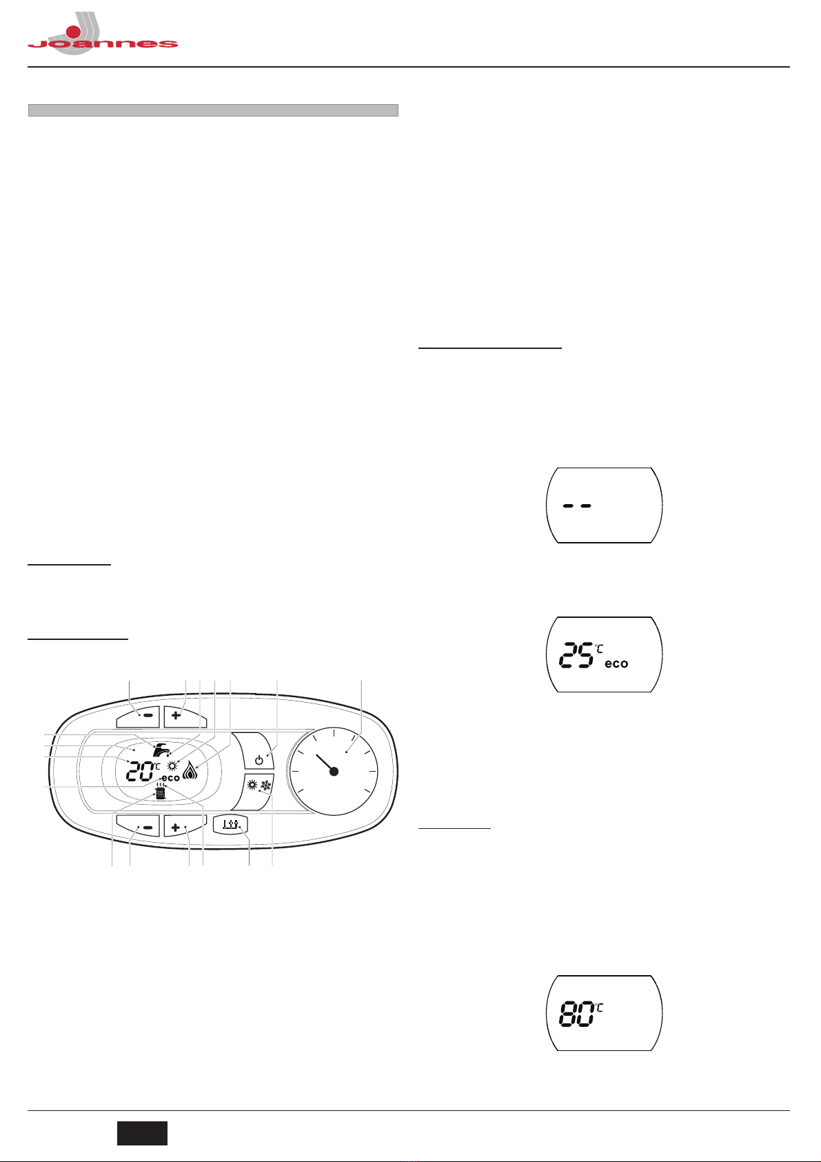
• portare la caldaia in modo stand-by
• premere i tasti sanitario part. 1 e 2 - fig. 1 per 10 secondi: il display visualizza
“b01“ lampeggiante.
• premere i tasti sanitario part. 1 e 2 - fig. 1 per impostare il parametro 00 (per il
funzionamento a metano) oppure 01 (per il funzionamento a GPL).
• premere i tasti sanitario part. 1 e 2 - fig. 1 per 10 secondi.
• la caldaia torna in modo stand-by
3. Regolare le pressioni minima e massima al bruciatore (rif. paragrafo relativo), impo-
stando i valori indicati in tabella dati tecnici per il tipo di gas utilizzato
4. Applicare la targhetta adesiva contenuta nel kit di trasformazione vicino alla targhet-
ta dei dati tecnici per comprovare l’avvenuta trasformazione.
Attivazione modalità TEST
Premere contemporaneamente i tasti riscaldamento (part. 3 e 4 - fig. 1) per 5 secondi
per attivare la modalità TEST. La caldaia si accende al massimo della potenza di riscal-
damento impostata come al paragrafo successivo.
Sul display, i simboli riscaldamento e sanitario (fig. 17) lampeggiano; accanto verrà vi-
sualizzata la potenza riscaldamento.
fig. 17 - Modalità TEST (potenza riscaldamento = 100%)
Premere i tasti riscaldamento (part. 3 e 4 - fig. 1) per aumentare o diminuire la potenza
(Minima=0%, Massima=100%).
Premendo il tasto sanitario “-” (part. 1 - fig. 1) la potenza della caldaia viene regolata
immediatamente al minimo (0%). Premendo il tasto sanitario “+” (part. 2 - fig. 1) la po-
tenza della caldaia viene regolata immediatamente al massimo (100%).
Nel caso in cui sia attiva la modalità TEST e vi sia un prelievo d’acqua calda sanitaria,
sufficiente ad attivare la modalità Sanitario, la caldaia resta in modalità TEST ma la Val-
vola 3 vie si posiziona in sanitario.
Per disattivare la modalità TEST, premere contemporaneamente i tasti riscaldamento
(part. 3 e 4 - fig. 1) per 5 secondi.
La modalità TEST si disabilita comunque automaticamente dopo 15 minuti oppure chiu-
dendo il prelievo d’acqua calda sanitaria (nel caso vi sia stato un prelievo d’acqua calda
sanitaria sufficiente ad attivare la modalità Sanitario).
Regolazione pressione al bruciatore
Questo apparecchio, essendo del tipo a modulazione di fiamma, ha due valori di pres-
sione fissi: quello di minima e quello di massima, che devono essere quelli indicati in ta-
bella dati tecnici in base al tipo di gas.
• Collegare un idoneo manometro alla presa di pressione “B” posta a valle della val-
vola gas.
• Attivare la modalità TEST (vedi cap. 4.1).
• Premendo il tasto Eco/Comfort per 2 secondi, si entra nella modalità Taratura val-
vola gas.
• La scheda si porta sull’impostazione “q02”; visualizzando, con una pressione dei ta-
sti sanitario, il valore attualmente salvato.
• Se la pressione letta sul Manometro è diversa dalla pressione massima nominale,
procedere ad incrementi/decrementi di 1 o 2 unità del parametro “q02” attraverso la
pressione dei tasti sanitario: dopo ogni modifica, il valore viene memorizzato; atten-
dere 10 secondi affinché la pressione si stabilizzi.
• Premere il tasto riscaldamento “-” (rif. 3 - fig. 1).
• La scheda si porta sull’impostazione “q01”; visualizzando, con una pressione dei ta-
sti sanitario, il valore attualmente salvato.
• Se la pressione letta sul Manometro è diversa dalla pressione minima nominale,
procedere ad incrementi/decrementi di 1 o 2 unità del parametro “q01” attraverso la
pressione dei tasti sanitario: dopo ogni modifica, il valore viene memorizzato; atten-
dere 10 secondi affinché la pressione si stabilizzi.
• Riverificare entrambe le regolazioni attraverso la pressione dei tasti riscaldamento
ed eventualmente correggerle ripetendo la procedura descritta in precedenza.
• Premendo il tasto Eco/Comfort per 2 secondi, si ritorna alla modalità TEST.
• Disattivare la modalità TEST (vedi cap. 4.1).
• Scollegare il manometro.
Perdite in m
eq
Aspirazione
aria
Scarico fumi
Verticale Orizzontale
Ø 80
TUBO
0.5 m M/F 1KWMA38A 0,5 0,5 1,0
1 m M/F 1KWMA83A 1,0 1,0 2,0
2 m M/F 1KWMA06K 2,0 2,0 4,0
CURVA
45° F/F 1KWMA01K 1,2 2,2
45° M/F 1KWMA65A 1,2 2,2
90° F/F 1KWMA02K 2,0 3,0
90° M/F 1KWMA82A 1,5 2,5
90° M/F + Presa test 1KWMA70U 1,5 2,5
TRONCHETTO
con presa test 1KWMA16U 0,2 0,2
per scarico condensa 1KWMA55U - 3,0
TEE
con scarico condensa 1KWMA05K - 7,0
TERMINALE
aria a parete 1KWMA85A 2,0 -
fumi a parete con antivento 1KWMA86A - 5,0
CAMINO
Aria/fumi sdoppiato 80/80 1KWMA84U - 12,0
Solo uscita fumi Ø80 1KWMA83U +
1KWMA86U
-4,0
Ø 100
RIDUZIONE
da Ø80 a Ø100 1KWMA03U 0,0 0,0
da Ø100 a Ø80 1,5 3,0
TUBO
1 m M/F 1KWMA08K 0,4 0,4 0,8
CURVA
45° M/F 1KWMA03K 0,6 1,0
90° M/F 1KWMA04K 0,8 1,3
TERMINALE
aria a parete 1KWMA14K 1,5 -
fumi a parete antivento 1KWMA29K - 3,0
Ø 60
TUBO 1 m M/F 010028X0 - 2.0 6.0
CURVA 90° M/F 010029X0 - 6.0
RIDUZIONE 80 - 60 010030X0 - 8.0
TERMINALE Fumi a parete 1KWMA90A - 7.0
ATTENZIONE: CONSIDERATE LE ALTE PERDITE DI CARICO DEGLI ACCESSORI
Ø60, UTILIZZARLI SOLO SE NECESSARIO ED IN CORRISPONDENZA
DELL’ULTIMO TRATTO SCARICO FUMI.
Tipo Descrizione
C2X
Aspirazione e scarico in canna fumaria comune (aspirazione e scarico nella medesima canna)
C4X
Aspirazione e scarico e in canne fumarie comuni separate, ma sottoposte a simili condizioni di vento
C8X
Scarico in canna fumaria singola o comune e aspirazione a parete
B3X
Aspirazione dal locale di installazione tramite condotto concentrico (che racchiude lo scarico) e scarico
in canna fumaria comune a tiraggio naturale
IMPORTANTE - IL LOCALE DEVE ESSERE DOTATO DI VENTILAZIONE APPROPRIATA
C8X C2X
C4X
0
1
4
2
3
reset
eco
comfort
I
I
I
I
I
I
I
I
I
I
I
I
I
I
I
I
I
I
I
I
I
I
I
I
I
I
I
I
I
I
I
I
I
I
I
I
I
I
I
I
I
I
I
I

CLIZIA D 32 AS
7
IT
cod. 3541C820 - Rev. 00 - 09/2012
Regolazione della potenza riscaldamento
Per regolare la potenza in riscaldamento posizionare la caldaia in funzionamento TEST
(vedi sez. 4.1). Premere i tasti riscaldamento part. 3 - fig. 1 per aumentare o diminuire la
potenza (minima = 00 - Massima = 100). Premendo il tasto reset entro 5 secondi, la po-
tenza massima resterà quella appena impostata. Uscire dal funzionamento TEST (vedi
sez. 4.1).
Menù configurazione
L’accesso al Menù di configurazione avviene premendo i tasti sanitario insieme per 10
secondi. Sono disponibili 7 parametri indicati dalla lettera “b”: i quali non sono modifica-
bili da Cronocomando Remoto.
Premendo i tasti Riscaldamento sarà possibile scorrere la lista dei parametri, rispettiva-
mente in ordine crescente o decrescente. Per visualizzare o modificare il valore di un pa-
rametro basterà premere i tasti Sanitario: la modifica verrà salvata automaticamente. Note:
1. I parametri che presentano più di una descrizione variano il proprio funzionamento
e/o range in relazione all’impostazione del parametro riportato tra parentesi.
2. I parametri che presentano più di una descrizione vengono ripristinati al valore di
default qualora venga modificato il parametro riportato tra parentesi.
L’uscita dal Menù di configurazione avviene premendo i tasti sanitario insieme per 10 se-
condi oppure automaticamente dopo 2 minuti.
Menù service
L’acceso al Menù Service della scheda avviene premendo il tasto Reset per 20 secondi.
Sono disponibili 4 sotto menù: premendo i tasti Riscaldamento sarà possibile scegliere,
rispettivamente in ordine crescente o decrescente, “tS”, “In”, “Hi” oppure “rE”. “tS” signi-
fica Menù Parametri Trasparenti, “In” significa Menù Informazioni, “Hi” significa Menù Hi-
story: una volta selezionato il sotto menù, per accedervi, sarà necessaria un’ulteriore
pressione del tasto Reset; “rE” significa Reset del Menù History: vedi descrizione.
“tS” - Menù Parametri Trasparenti
Sono disponibili 16 parametri indicati dalla lettera "P": i quali sono modificabili anche da
Cronocomando Remoto.
Premendo i tasti Riscaldamento sarà possibile scorrere la lista dei parametri, rispettiva-
mente in ordine crescente o decrescente. Per visualizzare o modificare il valore di un pa-
rametro basterà premere i tasti Sanitario: la modifica verrà salvata automaticamente.
fig. 18 - Valvola gas
A
- Presa di pressione a monte
B
- Presa di pressione a valle
I
- Connessione elettrica Valvola gas
R
- Uscita gas
S
- Entrata gas
fig. 19 - Connessione valvola gas
TYPE SGV100
Pi max 65 mbar
24 Vdc - class B+A
Indice Descrizione Range Default CLIZIA D 32 AS
b01 Selezione tipo gas 0=Metano 0=Metano 0=Metano
1=GPL
b02 Selezione tipo cal-
daia
1=Istantanea biter-
mico
1=Istantanea biter-
mico
2=Istantanea mono-
termico
2=Istantanea mono-
termico
3=Solo riscald. (valv.
3 vie)
4=Solo riscald. (circo-
latore)
b03 Selezione tipo
camera combustione
0=Camera Stagna
controllo combu-
stione
(senza PF)
0=Camera Stagna
con
controllo combu-
stione
0=Camera Stagna
con
controllo combu-
stione
(senza PF)
1=Camera Aperta
(con TF)
2=Camera Stagna
(con PF)
3=Camera Stagna
controllo Combu-
stione
(con TF su recupera-
tore)
4=LOW NOx Camera
Stagna controllo
Combustione
(senza PF)
5=LOW NOx Camera
Aperta
(con TF)
R
B
I
A
S
~ 65Ω
~ 24Ω
b04
Selezione tipo Scam-
biatore Primario
(b03=0)
0=Piano
0=Piano 0=Piano1=Omega
2=--
Ininfluente sulla rego-
lazione (b03=1) -- 0
Ininfluente sulla rego-
lazione (b03=2) -- 0
Selezione tipo Scam-
biatore Primario
(b03=3)
0=Piano
0=Piano1=Omega
2=--
Ininfluente sulla rego-
lazione (b03=4) -- 0
Ininfluente sulla rego-
lazione (b03=5) -- 0
b05
Selezione funziona-
mento
scheda relè LC32
(b02=1)
0=Valvola gas
esterna
0=Valvola gas
esterna
0=Valvola gas
esterna
1=Elettrovalvola cari-
camento impianto
2=Valvola 3 vie
solare
Ininfluente sulla rego-
lazione (b02=2) -- 0
Ininfluente sulla rego-
lazione (b02=3) -- 0
Ininfluente sulla rego-
lazione (b02=4) -- 0
b06 Frequenza Tensione
di Rete
0=50Hz 0=50Hz 0=50Hz
1=60Hz
b07
Tempo bruciatore
acceso Comfort
(b02=1)
0-20 secondi 5 secondi 5 secondi
Ininfluente sulla rego-
lazione (b02=2) -- 5
Ininfluente sulla rego-
lazione (b02=3) -- 5
Ininfluente sulla rego-
lazione (b02=4) -- 5
Indice Descrizione Range Default CLIZIA D 32 AS
P01 Offset rampa
d’accensione 0-40 10 10
P02 Rampa riscalda-
mento 1-20°C/minuto 5°C/minuto 5°C/minuto
P03 Tempo attesa riscal-
damento 0-10 minuti 2 minuti 2 minuti
P04 Post Circolazione
riscaldamento 0-20 minuti 6 minuti 6 minuti
P05 Massimo setpoint
utente riscaldamento 31-85°C 80°C 80°C
P06 Potenza massima
riscaldamento 0-100% 100% 100%
Indice Descrizione Range Default CLIZIA D 32 AS

CLIZIA D 32 AS
8IT cod. 3541C820 - Rev. 00 - 09/2012
Note:
1. I parametri che presentano più di una descrizione variano il proprio funzionamento
e/o range in relazione all’impostazione del parametro riportato tra parentesi.
2. I parametri che presentano più di una descrizione vengono ripristinati al valore di
default qualora venga modificato il parametro riportato tra parentesi.
3. Il parametro Potenza Massima Riscaldamento può essere modificato anche in Mo-
dalità Test.
Per tornare al Menù Service è sufficiente una pressione del tasto Reset. L’uscita dal
Menù Service della scheda avviene premendo il tasto Reset per 20 secondi oppure au-
tomaticamente dopo 15 minuti.
“In” - Menù Informazioni
Sono disponibili 7 informazioni.
Premendo i tasti Riscaldamento sarà possibile scorrere la lista delle informazioni, rispet-
tivamente in ordine crescente o decrescente. Per visualizzarne il valore basterà premere
i tasti Sanitario.
Note:
1. In caso di Sensore danneggiato, la scheda visualizzerà i trattini.
Per tornare al Menù Service è sufficiente una pressione del tasto Reset. L’uscita dal
Menù Service della scheda avviene premendo il tasto Reset per 20 secondi oppure au-
tomaticamente dopo 15 minuti.
“Hi” - Menù History
La scheda è in grado di memorizzare le ultime 11 anomalie: il dato Storico H1: rappre-
senta l’anomalia più recente che si è verificata; il dato Storico H10: rappresenta l’anoma-
lia meno recente che si è verificata.
I codici delle anomalie salvate vengono visualizzati anche sul relativo menù del Crono-
comando Remoto.
Premendo i tasti Riscaldamento sarà possibile scorrere la lista delle anomalie, rispetti-
vamente in ordine crescente o decrescente. Per visualizzarne il valore basterà premere
i tasti Sanitario.
Per tornare al Menù Service è sufficiente una pressione del tasto Reset. L’uscita dal
Menù Service della scheda avviene premendo il tasto Reset per 20 secondi oppure au-
tomaticamente dopo 15 minuti.
“rE” - Reset History
Premendo per 3 secondi il tasto Eco/comfort sarà possibile cancellare tutte le anomalie
memorizzate nel Menù History: automaticamente la scheda uscirà dal Menù Service, in
modo da confermare l’operazione.
L’uscita dal Menù Service della scheda avviene premendo il tasto Reset per 20 secondi
oppure automaticamente dopo 15 minuti.
4.2 Messa in servizio
Prima di accendere la caldaia
• Verificare la tenuta dell’impianto gas.
• Verificare la corretta precarica del vaso di espansione.
• Riempire l’impianto idraulico ed assicurare un completo sfiato dell’aria contenuta
nella caldaia e nell’impianto.
• Verificare che non vi siano perdite di acqua nell’impianto, nei circuiti acqua sanitaria,
nei collegamenti o in caldaia.
• Verificare l’esatto collegamento dell’impianto elettrico e la funzionalità dell’impianto
di terra.
• Verificare che il valore di pressione gas per il riscaldamento sia quello richiesto.
• Verificare che non vi siano liquidi o materiali infiammabili nelle immediate vicinanze
della caldaia
Verifiche durante il funzionamento
• Accendere l’apparecchio.
• Assicurarsi della tenuta del circuito del combustibile e degli impianti acqua.
• Controllare l’efficienza del camino e condotti aria-fumi durante il funzionamento del-
la caldaia.
• Controllare che la circolazione dell’acqua, tra caldaia ed impianti, avvenga corretta-
mente.
• Assicurarsi che la valvola gas moduli correttamente sia nella fase di riscaldamento
che in quella di produzione d’acqua sanitaria.
• Verificare la buona accensione della caldaia, effettuando diverse prove di accensio-
ne e spegnimento, per mezzo del termostato ambiente o del comando remoto.
• Assicurarsi che il consumo del combustibile indicato al contatore, corrisponda a
quello indicato nella tabella dati tecnici al cap. 5.
• Assicurarsi che senza richiesta di riscaldamento il bruciatore si accenda corretta-
mente all’apertura di un rubinetto dell’acqua calda sanitaria. Controllare che durante
il funzionamento in riscaldamento, all’apertura di un rubinetto dell’acqua calda, si ar-
resti il circolatore riscaldamento, e vi sia produzione regolare di acqua sanitaria.
• Verificare la corretta programmazione dei parametri ed eseguire le eventuali perso-
nalizzazioni richieste (curva di compensazione, potenza, temperature, ecc.).
P07
Spegnimento brucia-
tore in sanitario
(b02=1)
0=Fisso
0=Fisso 0=Fisso
1=Legato al setpoint
2=Solare(5)
3=Solare(10)
4=Solare(20)
Spegnimento brucia-
tore in sanitario
(b02=2)
0=Fisso
0=Fisso
1=Legato al setpoint
2=Solare(5)
3=Solare(10)
4=Solare(20)
Isteresi Bollitore
(b02=3) 0-4°C 2°C
Isteresi Bollitore
(b02=4) 0-4°C 2°C
P08
Tempo attesa sanita-
rio (b02=1) 0-60 secondi 30 secondi 60 secondi
Tempo attesa sanita-
rio (b02=2) 0-60 secondi 60 secondi
Tempo attesa sanita-
rio (b02=3) 0-60 secondi 30 secondi
Tempo attesa sanita-
rio (b02=4) 0-60 secondi 30 secondi
P09
Massimo setpoint
utente sanitario
(b02=1)
50-65°C 50°C 55°C
Massimo setpoint
utente sanitario
(b02=2)
50-65°C 55°C
Massimo setpoint
utente sanitario
(b02=3)
50-65°C 65°C
Massimo setpoint
utente sanitario
(b02=4)
50-65°C 65°C
P10
Temperatura fun-
zione Anti-inerzia
(b02=1)
70-85°C 70°C 0
Ininfluente sulla rego-
lazione (b02=2) -- 0
Temperatura man-
data in sanitario
(b02=3)
70-85°C 80°C
Temperatura man-
data in sanitario
(b02=4)
70-85°C 80°C
P11
Post Circolazione
funzione Anti-inerzia
(b02=1)
0-5 Secondi 0 secondi 30 secondi
Post Circolazione
sanitario (b02=2) 0-60 Secondi
Post Circolazione
sanitario (b02=3) 0-60 Secondi
Post Circolazione
sanitario (b02=4) 0-60 Secondi
P12 Potenza massima
sanitario 0-100% 100% 100%
P13 Potenza minima
assoluta 0-100% 0% 0%
P14 Post-Ventilazione 0=Default 0=Default 0=Default
1=50 secondi
P15
Offset limite CO2
(b03=0)
0 (Minimo)
30 (Massimo) 20 20
Ininfluente sulla rego-
lazione (b03=1) --
Ininfluente sulla rego-
lazione (b03=2) --
Offset limite CO2
(b03=3)
0 (Minimo)
30 (Massimo)
Offset limite CO2
(b03=4)
0 (Minimo)
30 (Massimo) 20
Ininfluente sulla rego-
lazione (b03=5) -- 20
P16 Intervento protezione
scambiatore
0=No F43
10°C/secondo 10°C/secondo
1-15=1-15°C/
secondo
Indice Descrizione Range Default CLIZIA D 32 AS
Indice Descrizione Range
t01 Sensore NTC Riscaldamento (°C) tra 05 e 125 °C
t02 Sensore NTC Sicurezza (°C) tra 05 e 125 °C
t03 Sensore NTC Sanitario (°C) tra 05 e 125 °C
t04 Sensore NTC Esterno (°C) tra -30 e 70°C (I valori negativi lampeggiano)
L05 Potenza bruciatore attuale (%) 00%=Minimo, 100%=Massimo
F06 Resistenza Fiamma attuale (Ohm) 00-99 Ohm (-- = bruciatore spento)
St07 Step Ventilatore (Numero) 0=Off, 1=Min, 2=Med, 3=Max

CLIZIA D 32 AS
9
IT
cod. 3541C820 - Rev. 00 - 09/2012
4.3 Manutenzione
Controllo periodico
Per mantenere nel tempo il corretto funzionamento dell’apparecchio, è necessario far
eseguire da personale qualificato un controllo annuale che preveda le seguenti verifiche:
• I dispositivi di comando e di sicurezza (valvola gas, flussometro, termostati, ecc.)
devono funzionare correttamente.
• Il circuito di evacuazione fumi deve essere in perfetta efficienza.
(Caldaia a camera stagna: ventilatore, pressostato, ecc. - La camera stagna deve
essere a tenuta: guarnizioni, pressacavi ecc.)
(Caldaia a camera aperta: antirefoleur, termostato fumi, ecc.)
• I condotti ed il terminale aria-fumi devono essere liberi da ostacoli e non presentare
perdite
• Il bruciatore e lo scambiatore devono essere puliti ed esenti da incrostazioni. Per
l’eventuale pulizia non usare prodotti chimici o spazzole di acciaio.
• L'elettrodo deve essere libero da incrostazioni e correttamente posizionato.
fig. 20 - Posizionamento elettrodo
• Gli impianti gas e acqua devono essere a tenuta.
• La pressione dell’acqua dell’impianto a freddo deve essere di circa 1 bar; in caso
contrario riportarla a questo valore.
• La pompa di circolazione non deve essere bloccata.
• Il vaso d’espansione deve essere carico.
• La portata gas e la pressione devono corrispondere a quanto indicato nelle rispetti-
ve tabelle.
4.4 Risoluzione dei problemi
Diagnostica
La caldaia è dotata di un avanzato sistema di autodiagnosi. Nel caso di un’anomalia alla
caldaia, il display lampeggia insieme al simbolo anomalia (part. 11 - fig. 1) indicando il
codice dell’anomalia.
Vi sono anomalie che causano blocchi permanenti (contraddistinte con la lettera “A”):
per il ripristino del funzionamento è sufficiente premere il tasto RESET (part. 6 - fig. 1)
per 1 secondo oppure attraverso il RESET del cronocomando remoto (opzionale) se in-
stallato; se la caldaia non riparte è necessario risolvere l’anomalia.
Altre anomalie causano blocchi temporanei (contraddistinte con la lettera “F”) che ven-
gono ripristinati automaticamente non appena il valore rientra nel campo di funziona-
mento normale della caldaia.
Lista anomalie
Tabella. 9
Codice
anomalia Anomalia Possibile causa Soluzione
A01
Mancata accensione del
bruciatore
Mancanza di gas
Controllare che l’afflusso di gas alla
caldaia sia regolare e che sia stata
eliminata l’aria dalle tubazioni
Anomalia elettrodo di rivelazione/
accensione
Controllare il cablaggio dell’elettrodo
e che lo stesso sia posizionato corret-
tamente e privo di incrostazioni
Valvola gas difettosa Verificare e sostituire la valvola a gas
Cablaggio valvola gas interrotto Verificare il cablaggio
Potenza di accensione troppo
bassa Regolare la potenza di accensione
A02
Segnale fiamma presente
con bruciatore spento
Anomalia elettrodo Verificare il cablaggio dell’elettrodo di
ionizzazione
Anomalia scheda Verificare la scheda
A03
Intervento protezione
sovra-temperatura
Sensore riscaldamento danneg-
giato
Controllare il corretto posizionamento
e funzionamento del sensore di riscal-
damento
Mancanza di circolazione d’acqua
nell’impianto Verificare il circolatore
Presenza aria nell’impianto Sfiatare l’impianto
F04
Anomalia parametri scheda Errata impostazione parametro
scheda
Verificare ed eventualmente modifi-
care il parametro scheda
F05
Anomalia parametri scheda Errata impostazione parametro
scheda
Verificare ed eventualmente modifi-
care il parametro scheda
Anomalia ventilatore
Cablaggio interrotto Verificare il cablaggio
Ventilatore difettoso Verificare il ventilatore
Anomalia scheda Verificare la scheda
A06
Mancanza fiamma dopo
fase di accensione
Bassa pressione nell’impianto gas Verificare la pressione dal gas
Taratura pressione minima brucia-
tore
Verificare le pressioni
3
±
0 5
= =
F07
Anomalia parametri scheda Errata impostazione parametro
scheda
Verificare ed eventualmente modifi-
care il parametro scheda
A09
Anomalia valvola gas
Cablaggio interrotto Verificare il cablaggio
Valvola gas difettosa Verificare ed eventualmente sostitu-
ire la valvola gas
F10
Anomalia sensore di man-
data 1
Sensore danneggiato Verificare il cablaggio o sostituire il
sensore
Cablaggio in corto circuito
Cablaggio interrotto
F11
Anomalia sensore sanitario
Sensore danneggiato Verificare il cablaggio o sostituire il
sensore
Cablaggio in corto circuito
Cablaggio interrotto
F14
Anomalia sensore di man-
data 2
Sensore danneggiato Verificare il cablaggio o sostituire il
sensore
Cablaggio in corto circuito
Cablaggio interrotto
A16
Anomalia valvola gas
Cablaggio interrotto Verificare il cablaggio
Valvola gas difettosa Verificare ed eventualmente sostitu-
ire la valvola gas
F20
Anomalia controllo combu-
stione
Anomalia ventilatore Verificare ventilatore e cablaggio ven-
tilatore
Diaframma errato Verificare ed eventualmente sostitu-
ire il diaframma
Camino non correttamente dimen-
sionato oppure ostruito Verificare il camino
A21
Anomalia cattiva combu-
stione
Anomalia F20 generata 6 volte
negli ultimi 10 minuti Vedi anomalia F20
A23
Anomalia parametri scheda Errata impostazione parametro
scheda
Verificare ed eventualmente modifi-
care il parametro scheda
A24
Anomalia parametri scheda Errata impostazione parametro
scheda
Verificare ed eventualmente modifi-
care il parametro scheda
F34
Tensione di alimentazione
inferiore a 180V. Problemi alla rete elettrica Verificare l’impianto elettrico
F35
Frequenza di rete anomala Problemi alla rete elettrica Verificare l’impianto elettrico
F37
Pressione acqua impianto
non corretta
Pressione troppo bassa Caricare impianto
Pressostato acqua non collegato
o danneggiato Verificare il sensore
F39
Anomalia sonda esterna
sonda danneggiata o corto cir-
cuito cablaggio
Verificare il cablaggio o sostituire il
sensore
sonda scollegata dopo aver atti-
vato la temperatura scorrevole
Ricollegare la sonda esterna o disabi-
litare la temperatura scorrevole
A41
Posizionamento sensori Sensore mandata o sensore sani-
tario staccato dal tubo
Controllare il corretto posizionamento
e funzionamento dei sensori
F42
Anomalia sensore riscalda-
mento Sensore danneggiato Sostituire il sensore
F43
Intervento protezione scam-
biatore.
Mancanza di circolazione H
2
O
impianto Verificare il circolatore
Aria nell’impianto Sfiatare l’impianto
F50
Anomalia Valvola Gas
Cablaggio Operatore modulante
interrotto Verificare il cablaggio
Valvola Gas difettosa Verificare ed eventualmente sostitu-
ire la valvola gas
A51
Anomalia Cattiva combu-
stione
Ostruzione camino scarico/aspira-
zione Verificare il camino
Codice
anomalia Anomalia Possibile causa Soluzione

CLIZIA D 32 AS
10 IT cod. 3541C820 - Rev. 00 - 09/2012
5. CARATTERISTICHE E DATI TECNICI
Tabella. 10 - Legenda figure cap. 5
5.1 Vista generale e componenti principali
fig. 21 - Vista generale CLIZIA D 32 AS
5.2 Circuito idraulico
fig. 22 - Circuito riscaldamento
fig. 23 - Circuito sanitario
5
Camera stagna
38
Flussostato
7
Entrata gas
39
Limitatore di portata acqua
8
Uscita acqua sanitaria
42
Sensore di temperatura sanitaria
9
Entrata acqua sanitaria
44
Valvola gas
10
Mandata impianto
56
Vaso di espansione
11
Ritorno impianto
72
Termostato ambiente (non fornito)
14
Valvola di sicurezza
74
Rubinetto di riempimento impianto
16
Ventilatore
81
Elettrodo d’accensione e rilevazione
19
Camera combustione
95
Valvola deviatrice
22
Bruciatore
114
Pressostato acqua
27
Scambiatore in rame per riscaldamento e sanitario
138
Sonda esterna (non fornito)
28
Collettore fumi
139
Unità ambiente (non fornito)
29
Collettore uscita fumi
187
Diaframma fumi
32
Circolatore riscaldamento
194
Scambiatore acqua sanitaria
36
Sfiato aria automatico
241
Bypass automatico
37
Filtro entrata acqua fredda
278
Sensore doppio (Sicurezza + Riscaldamento)
44 32
114
36
14
19
27
28
29
5
16
81
95
278
42 38
37
10 7 11
194
39 74
187
22
56
89
56
27
14
74
32
38
1110 8 9
278
95
241 42
114 36
194
56
27
14
74
32
38
1110 8 9
278
95
241 42
114 36
194

CLIZIA D 32 AS
11
IT
cod. 3541C820 - Rev. 00 - 09/2012
5.3 Tabella dati tecnici 5.4 Diagrammi
Diagrammi pressione - potenza CLIZIA D 32 AS
A = GPL - B = METANO
Perdite di carico / prevalenza circolatori CLIZIA D 32 AS
A = Perdite di carico caldaia - 1,2 e 3 = Velocità circolatore
Dato Unità CLIZIA D 32 AS
Portata termica max kW 34.4 (Q)
Portata termica min kW 11.5 (Q)
Potenza Termica max riscaldamento kW 32.0 (P)
Potenza Termica min riscaldamento kW 9.9 (P)
Potenza Termica max sanitario kW 32.0
Potenza Termica min sanitario kW 9.9
Rendimento Pmax (80-60°C) % 93.1
Rendimento 30% % 91.0
Classe efficienza direttiva 92/42 EEC -
Classe di emissione NOx - 3 (<150 mg/kWh) (NOx)
Ugelli bruciatore G20 n° x Ø 15 x 1.35
Pressione gas alimentazione G20 mbar 20.0
Pressione gas max al bruciatore (G20) mbar 12.0
Pressione gas min al bruciatore (G20) mbar 1.5
Portata gas max G20 m
3
/h 3.64
Portata gas min G20 m
3
/h 1.22
Ugelli bruciatore G31 n° x Ø 15 x 0.79
Pressione gas alimentazione G31 mbar 37
Pressione gas max al bruciatore (G31) mbar 35.0
Pressione gas min al bruciatore (G31) mbar 5.0
Portata gas max G31 kg/h 2.69
Portata gas min G31 kg/h 0.90
Pressione max esercizio riscaldamento bar 3 (PMS)
Pressione min esercizio riscaldamento bar 0.8
Temperatura max riscaldamento °C 90 (tmax)
Contenuto acqua riscaldamento litri 1.2
Capacità vaso di espansione riscaldamento litri 10
Pressione precarica vaso di espansione riscaldamento bar 1
Pressione max di esercizio sanitario bar 9 (PMW)
Pressione min di esercizio sanitario bar 0.25
Portata sanitaria Dt 25°C l/min 18.3
Portata sanitaria Dt 30°C l/min 15.2 (D)
Grado protezione IP X5D
Tensione di alimentazione V/Hz 230V/50Hz
Potenza elettrica assorbita W 135
Potenza elettrica assorbita sanitario W 135
Peso a vuoto kg 35
Tipo di apparecchio C
12
-C
22
-C
32
-C
42
-C
52
-C
62
-C
72
-C
82
-B
22
PIN CE 0461BR0842
A
B
0
1
2
3
4
5
6
7
0 500 1.000 1.500 2.000
Q [l/h]
H [m H
2
O]
A
3
1
2

CLIZIA D 32 AS
12 IT cod. 3541C820 - Rev. 00 - 09/2012
5.5 Schema elettrico
fig. 24 - Circuito elettrico
AAttenzione: Prima di collegare il termostato ambiente o il cronocomando re-
moto, togliere il ponticello sulla morsettiera.
81
1k
W
L
N
230V
50 Hz
16
N
L
32
L
N
°
T
°
T
278
°
T
42
4321
44
38114
ABM01
LC32
321
95
72
139
138

CLIZIA D 32 AS
13
EN
cod. 3541C820 - Rev. 00 - 09/2012
EN
1. GENERAL WARNINGS
• Carefully read and follow the instructions contained in this instruction booklet.
• After boiler installation, inform the user regarding its operation and give him this
manual, which is an integral and essential part of the product and must be kept with
care for future reference.
• Installation and maintenance must be carried out by professionally qualified person-
nel, in compliance with the current regulations and according to the manufacturer's
instructions. Do not carry out any operation on the sealed control parts.
• Incorrect installation or inadequate maintenance can result in damage or injury. The
Manufacturer declines any liability for damage due to errors in installation and use,
or failure to follow the instructions.
• Before carrying out any cleaning or maintenance operation, disconnect the unit from
the electrical power supply using the switch and/or the special cut-off devices.
• In case of a fault and/or poor operation, deactivate the unit and do not try to repair
it or directly intervene. Contact professionally qualified personnel. Any repair/re-
placement of the products must only be carried out by qualified personnel using orig-
inal replacement parts. Failure to comply with the above could affect the safety of
the unit.
• This unit must only be used for its intended purpose. Any other use is deemed im-
proper and therefore hazardous.
• The packing materials are potentially hazardous and must not be left within the
reach of children.
• The unit must not be used by people (including children) with limited physical, sen-
sory or mental abilities or without experience and knowledge of it, unless instructed
or supervised in its use by someone responsible for their safety.
• The unit and its accessories must be appropriately disposed of, in compliance with
the current regulations.
• The images given in this manual are a simplified representation of the product. In
this representation there may be slight and insignificant differences with respect to
the product supplied.
2. OPERATING INSTRUCTIONS
2.1 Introduction
CLIZIA D 32 AS is a high-efficiency heat generator for heating and domestic hot water
production, running on natural gas, equipped with an open-flue burner with electronic ig-
nition, sealed chamber with forced ventilation, and microprocessor control system, de-
signed for installation indoors or outdoors in a partially protected place (in compliance
with EN 297/A6) for temperatures to -5°C.
2.2 Control panel
Panel
fig. 1 - Control panel
Key of panel fig. 25
1DHW temperature setting decrease button
2DHW temperature setting increase button
3Heating system temperature setting decrease button
4Heating system temperature setting increase button
5Display
6"Sliding Temperature" Menu - Summer/Winter mode selection - Reset button
7Unit On/Off - Economy/Comfort mode selection button
8DHW symbol
9DHW mode
10 Summer mode
11 Multifunction
12 Eco (Economy) mode
13 Heating
14 Heating symbol
15 Burner lit and actual power level (flashing during combustion fault function)
16 Service Tool connection
17 Water gauge
Indication during operation
Heating
A heating demand (generated by the Room Thermostat or Remote Timer Control) is in-
dicated by flashing of the hot air above the radiator on the display.
The display (detail 11 - fig. 25) shows the actual heating delivery temperature and, during
heating standby time, the message “d2”.
Domestic hot water (DHW)
A DHW demand (generated by drawing domestic hot water) is indicated by flashing of
the hot water under the tap on the display.
The display (detail 11 - fig. 25) shows the actual DHW outlet temperature and, during
DHW standby time, the message “d1“.
Comfort
A Comfort demand (reinstatement of temperature inside the boiler) is indicated by flash-
ing of the water under the tap on the display. The display (detail 11 - fig. 25) shows the
actual temperature of the water in the boiler.
Fault
In case of a fault (see cap. 9.4) the display shows the fault code (detail 11 - fig. 25) and,
during safety standby times, the messages "d3" and "d4".
2.3 Lighting and turning off
Connection to the power supply
• During the first 5 seconds the display will also show the card software release.
• Open the gas cock ahead of the boiler.
• The boiler is now ready to function automatically whenever domestic hot water is
drawn or in case of a heating demand (generated by Room Thermostat or Remote
Temperature Control).
Turning the boiler off and on
Press the on/off button (detail 7 - fig. 25) for 5 seconds.
fig. 2 - Turning the boiler off
When the boiler is turned off, the PCB is still powered. Domestic hot water and heating
are disabled. The antifreeze system remains activated. To relight the boiler, press the
on/off button (detail 7 fig. 25) again for 5 seconds.
fig. 3
The boiler will be immediately ready to work whenever domestic hot water is drawn or in
case of a heating demand (generated by the Room Thermostat or the Remote Timer
control).
BThe antifreeze system does not work when the power and/or gas to the unit are
turned off. To avoid damage caused by freezing during long idle periods in win-
ter, it is advisable to drain all water from the boiler, DHW circuit and system; or
drain just the DHW circuit and add a suitable antifreeze to the heating system,
complying with that prescribed insec. 8.3.
2.4 Adjustments
Summer/Winter Switchover
Press the summer/winter button (detail 6 - fig. 25) for 2 seconds.
The display activates the Summer symbol (detail 10 - fig. 25): the boiler will only deliver
domestic hot water. The antifreeze system remains activated.
To deactivate the Summer mode, press the summer/winter button (detail 6 - fig. 25)
again for 2 seconds.
Heating temperature adjustment
Use the heating buttons (details 3 and 4 - fig. 25) to vary the temperature from a min. of
30°C to a max. of 80°C; in any case, it is advisable not to operate the boiler below 45°C.
fig. 4
0
1
4
2
3
reset
eco
comfort
915
13
12
11
8
1
36
7102
16414
5
17
I
I
I
I
I
I
I
I
I

CLIZIA D 32 AS
14 EN cod. 3541C820 - Rev. 00 - 09/2012
Domestic hot water (DHW) temperature adjustment
Use the DHW buttons (details 1 and 2 - fig. 25) to adjust the temperature from a min. of
40°C to a max. of 55°C.
fig. 5
Room temperature adjustment (with optional room thermostat)
Using the room thermostat, set the temperature required in the rooms. If the room ther-
mostat is not installed, the boiler will keep the system at the set system delivery setpoint
temperature.
Room temperature adjustment (with optional remote timer control)
Using the remote timer control, set the required temperature in the rooms. The boiler will
adjust the system water according to the required room temperature. For operation with
remote timer control, please refer to the relevant instruction manual.
ECO/COMFORT selection
The unit has a function that ensures a high domestic hot water delivery speed and max-
imum comfort for the user. When the device is activated (COMFORT mode), the water
contained in the boiler is kept hot, thereby ensuring immediate availability of hot water
on opening the tap, without waiting times.
The user can deactivate the device (ECO mode) by pressing the eco/comfort button
(detail 7 - fig. 25). In ECO mode the display activates the ECO symbol (detail 12 - fig. 25).
To activate the COMFORT mode, press the eco/comfort button (detail 7 - fig. 25) again.
Sliding Temperature
When the optional external probe is installed, the boiler adjustment system works with
"Sliding Temperature”. In this mode, the temperature of the heating system is controlled
according to the outside weather conditions, to ensure high comfort and energy saving
throughout the year. In particular, the system delivery temperature is decreased as the
outside temperature increases, according to a specific "compensation curve”.
With Sliding Temperature adjustment, the temperature set with the heating buttons (de-
tail 3 - fig. 25) becomes the maximum system delivery temperature. It is advisable to set
a maximum value to allow system adjustment throughout its useful operating range.
The boiler must be adjusted at the time of installation by qualified personnel. Possible
adjustments can in any case be made by the user to improve comfort.
Compensation curve and curve offset
Press the reset button (detail 6 - fig. 25) for 5 seconds to access the "Sliding tempera-
ture" menu; the display shows "CU" flashing.
Use the DHW buttons (detail 1 - fig. 25) to adjust the curve from 1 to 10 according to the
characteristic. By setting the curve to 0, sliding temperature adjustment is disabled.
Press the heating buttons (detail 3 - fig. 25) to access parallel curve offset; the display
shows "OF" flashing. Use the DHW buttons (detail 1 - fig. 25) to adjust the parallel curve
offset according to the characteristic (fig. 30).
Press the reset button (detail 6 - fig. 25) again for 5 seconds to exit the "Sliding Temper-
ature" menu.
If the room temperature is lower than the required value, it is advisable to set a higher
order curve and vice versa. Proceed by increasing or decreasing in steps of one and
check the result in the room.
fig. 6 - Example of compensation parallel curve offset
Adjustments from Remote Timer Control
AIf the Remote Timer Control (optional) is connected to the boiler, the above ad-
justments are managed according to that given in table 11.
Table. 1
System water pressure adjustment
The filling pressure with system cold, read on boiler water gauge (detail 17 - fig. 25), must
be approx. 1.0 bar. If the system pressure falls to values below minimum, the boiler stops
and fault F37 is displayed. Operate the filling cock detail 1 fig. 31 and bring it to the initial
value. Always close the filling cock at the end of the operation.
fig. 7 - Filling cock
3. INSTALLATION
3.1 General Instructions
BOILER INSTALLATION MUST ONLY BE PERFORMED BY QUALIFIED PERSON-
NEL, IN ACCORDANCE WITH ALL THE INSTRUCTIONS GIVEN IN THIS TECHNICAL
MANUAL, THE PROVISIONS OF CURRENT LAW, THE PRESCRIPTIONS OF NA-
TIONAL AND LOCAL STANDARDS AND THE RULES OF PROPER WORKMANSHIP.
3.2 Place of installation
The combustion circuit is sealed with respect to the place of installation, therefore the
unit can be installed in any room. However, the place of installation must be sufficiently
ventilated to prevent the creation of dangerous conditions in case of even small gas
leaks. This safety standard is required by the EEC Directive no. 2009/142 for all gas
units, including those with sealed chamber
The unit is suitable for operation in a partially protected place in compliance with EN 297
pr A6, for temperatures to -5°C. It is advisable to install the boiler under the slope of a
roof, inside a balcony or in a sheltered recess.
Therefore the place of installation must be free of dust, flammable materials or objects
or corrosive gases.
The boiler is arranged for wall mounting and comes standard with a hooking bracket. Fix
the bracket to the wall according to the measurements given in the cover drawing and
hook the boiler on it. A metal template for marking the drilling points on the wall is avail-
able by request. The wall fixing must ensure stable and effective support for the gener-
ator.
AIf the unit is enclosed in a cabinet or mounted alongside, a space must be pro-
vided for removing the casing and for normal maintenance operations
I
I
I
I
I
I
I
I
I
20
30
40
50
60
70
80
90
85
20 10 0 -10 -20
1
2
3
4
5
6
8910 7
20 10 0 -10 -20
20
30
40
50
60
70
80
90
85
1
2
3
4
568910 7
OFFSET = 20 OFFSET = 40
Heating temperature setting
Adjustment can be made from the Remote Timer Control menu
and the boiler control panel.
DHW temperature adjustment
Adjustment can be made from the Remote Timer Control menu
and the boiler control panel.
Summer/Winter Switchover
Summer mode has priority over a possible Remote Timer Control
heating demand.
Eco/Comfort selection
On disabling DHW from the Remote Timer Control menu, the
boiler selects the Economy mode. In this condition, the
eco/com-
fort
button (detail 7 - fig. 25) on the boiler panel is disabled.
On enabling DHW from the Remote Timer Control menu, the
boiler selects the Comfort mode. In this condition it is possible
select one of the two modes with the
eco/comfort
button (detail 7
- fig. 25) on the boiler panel.
Sliding Temperature
Both the Remote Timer Control and the boiler card manage Slid-
ing Temperature adjustment: the boiler card Sliding Temperature
has priority.
1

CLIZIA D 32 AS
15
EN
cod. 3541C820 - Rev. 00 - 09/2012
3.3 Plumbing connections
Important
BThe safety valve outlet must be connected to a funnel or collection pipe to pre-
vent water spurting onto the floor in case of overpressure in the heating circuit.
Otherwise, if the discharge valve cuts in and floods the room, the boiler manu-
facturer cannot be held liable.
BBefore making the connection, check that the unit is arranged for operation with
the type of fuel available and carefully clean all the system pipes.
Carry out the relevant connections according to the cover diagram and the symbols giv-
en on the unit.
Note: The unit has an internal bypass in the heating circuit.
Water system characteristics
In the presence of water harder than 25° Fr (1°F = 10ppm CaCO3), use suitably treated
water in order to avoid possible scaling in the boiler.
Antifreeze system, antifreeze fluids, additives and inhibitors
When necessary, antifreeze fluids, additives and inhibitors can be used only if the man-
ufacturer of such fluids or additives guarantees that they are suitable and do not cause
damage to the exchanger or other components and/or materials of the boiler and system.
Do not use generic antifreeze fluids, additives or inhibitors that are not specific for use in
heating systems and compatible with the materials of the boiler and system.
3.4 Gas connection
The gas must be connected to the relevant union (see figure on cover) in conformity with
the current regulations, with a rigid metal pipe or with a continuous surface flexible s/steel
tube, installing a gas cock between the system and boiler. Make sure all the gas connec-
tions are tight.
3.5 Electrical connections
Important
BThe unit must be connected to an efficient earthing system in conformity with
current safety regulations. Have the efficiency and suitability of the earthing
system checked by professionally qualified personnel; the Manufacturer de-
clines any liability for damage caused by failure to earth the system.
The boiler is prewired and provided with a "Y" type cable (without plug) for con-
nection to the electric line. The connections to the power supply must be per-
manent and equipped with a double-pole switch with contact opening distance
of at least 3 mm, installing fuses of max. 3A between the boiler and the line.
Make sure to respect the polarities (LINE: brown wire / NEUTRAL: blue wire /
EARTH: yellow/green wire) in connections to the electric line.
BThe unit's power cable must not be replaced by the user; if damaged, switch
the unit off and have the cable replaced by professionally qualified personnel.
If replacing the power cable, only use "HAR H05 VV-F" 3x0.75 mm2 cable with
max. ext. diameter of 8 mm.
Room thermostat (optional)
BIMPORTANT: THE ROOM THERMOSTAT MUST HAVE VOLTAGE-FREE
CONTACTS. CONNECTING 230 V TO THE ROOM THERMOSTAT TERMI-
NALS WILL PERMANENTLY DAMAGE THE ELECTRONIC BOARD.
When connecting time controls or a timer, do not take the power supply for
these devices from their breaking contacts Their power supply must be by
means of direct connection from the mains or with batteries, depending on the
kind of device.
Accessing the electrical terminal block
The electrical terminal block can be accessed after removing the casing. The layout of
the terminals for the various connections is also given in the wiring diagram in fig. 48.
fig. 8 - Accessing the terminal block
3.6 Fume ducts
Important
The unit is a "C type" with sealed chamber and forced draught, the air inlet and fume out-
let must be connected to one of the following extraction/suction systems. The unit is ap-
proved for operation with all the Cny flue configurations given on the dataplate. Some
configurations may be expressly limited or not permitted by law, standards or local reg-
ulations. Before installation, check and carefully follow the instructions. Also, comply with
the instructions on the positioning of wall and/or roof terminals and the minimum distanc-
es from windows, walls, ventilation openings, etc.
Baffles
Boiler operation requires fitting the baffles supplied with the unit. Make sure the boiler
has the correct baffle (when used) and that it is properly positioned .
ABaffle replacement with boiler not installed
BBaffle replacement with boiler and fume ducts already installed
123456
72
139
138
34
A
1
2
B
3
2
1
4
5
6

CLIZIA D 32 AS
16 EN cod. 3541C820 - Rev. 00 - 09/2012
Connection with coaxial pipes
fig. 9 - Examples of connection with coaxial pipes ( = Air / = Fumes)
Table. 2 - Typology
For coaxial connection, fit the unit with one of the following starting accessories. For the
wall hole dimensions, refer to the figure on the cover.
Table. 3 - Starting accessories for coaxial ducts
Table. 4 - Baffles for coaxial ducts
Connection with separate pipes
fig. 14 - Examples of connection with separate pipes ( = Air / = Fumes)
Table. 5 - Typology
For the connection of separate ducts, fit the unit with the following starting accessory:
fig. 15 - Starting accessory for separate ducts
Before installation, check the baffle to be used and that the maximum permissible length
is not exceeded, by means of a simple calculation:
1. Completely establish the layout of the system of split flues, including accessories
and outlet terminals.
2. Consult the table 17 and identify the losses in meq (equivalent metres) of every com-
ponent, according to the installation position.
3. Check that the sum total of losses is less than or equal to the maximum permissible
length in table 16.
Table. 6 - Baffles for separate ducts
Type Description
C1X
Wall horizontal exhaust and inlet
C3X
Roof vertical exhaust and inlet
Code 010006X0 - 08522870
fig. 10
Code 010008X0 - 08522880
fig. 11
Code 010007X0
fig. 12
Code 08522890
fig. 13
Coaxial 60/100 Coaxial 80/125
Max. permissible length 5 m 10 m
Reduction factor 90° bend 1 m 0.5 m
Reduction factor 45° bend 0.5 m 0.25 m
Baffle to use
0 ÷ 2 m Ø 45 0 ÷ 3 m Ø 45
2 ÷ 5 m no baffle 3 ÷ 10 m no baffle
C
1X
C
1X
C
3X
C
3X
C
3X
C
1X
Ø
100
Ø
60
45.6
Ø126
Ø82
Ø60
Ø130
100
118
Ø
100
Ø
60
68
20
26 89
118
Ø
100
Ø
60
Ø
100
Ø
60
Type Description
C1X
Wall horizontal exhaust and intake. The inlet/outlet terminals must be concentric or close enough to be
undergo similar wind conditions (within 50 cm)
C3X
Roof vertical exhaust and intake. Inlet/outlet terminals like for C12
C5X
Wall or roof exhaust and intake separate or in any case in areas with different pressures. The exhaust
and intake must not be positioned on opposite walls.
C6X
Intake and exhaust with separately certified pipes (EN 1856/1)
B2X
Intake from installation room and wall or roof exhaust
IMPORTANT - THE ROOM MUST BE PROVIDED WITH APPROPRIATE VENTILATION
CLIZIA D 32 AS
Max. permissible length
48 m
eq
Baffle to use
0 - 15 m
eq
Ø 45
15 - 35 m
eq
Ø 50
35 - 48 m
eq
No baffle
C5x
C
3x
B2x C1x
max 50 cm
80
010011X0
0.852290.0
80
32
50

CLIZIA D 32 AS
17
EN
cod. 3541C820 - Rev. 00 - 09/2012
Table. 7 - Accessories
Connection to collective flues
fig. 16 - Examples of connection to flues ( = Air / = Fumes)
Table. 8 - Typology
If the boiler is to be connected CLIZIA D 32 AS to a collective flue or a single flue with
natural draught, the flue or chimney must be expressly designed by professionally qual-
ified technical personnel in conformity with the current regulations and be suitable for
sealed chamber units equipped with fan.
4. SERVICE AND MAINTENANCE
4.1 Adjustments
Gas conversion
The unit can operate on natural gas or LPG and is factory-set for use with one of these
two gases, as clearly shown on the packing and on the dataplate. Whenever a gas dif-
ferent from that for which the unit is arranged has to be used, the special conversion kit
will be required, proceeding as follows:
1. Replace the nozzles at the main burner, fitting the nozzles specified in the technical
data table in cap. 10, according to the type of gas used
2. Modify the parameter for the type of gas:
• put the boiler in standby mode
• press the DHW buttons details 1 and 2 - fig. 25 for 10 seconds: the display
shows “b01“ blinking.
• Press the DHW buttons (details 1 and 2 - fig. 25) to set parameter 00 (for nat-
ural gas operation) or 01 (for LPG operation).
• press the DHW buttons details 1 and 2 - fig. 25 for 10 seconds.
• the boiler will return to standby mode
3. Adjust the minimum and maximum pressures at the burner (ref. relevant para-
graph), setting the values given in the technical data table for the type of gas used
4. Apply the sticker contained in the conversion kit, near the dataplate as proof of the
conversion.
TEST mode activation
Press the heating buttons (details 3 and 4 - fig. 25) together for 5 seconds to activate the
TEST mode. The boiler lights at the maximum heating power set as described in the fol-
lowing section.
The heating and DHW symbols (fig. 41) flash on the display; the heating power will ap-
pear alongside.
fig. 17 - TEST mode (heating power = 100%)
Press the heating buttons (details 3 and 4 - fig. 25) to increase or decrease the power
(Min.=0%, Max.=100%).
By pressing the DHW “-” button (detail 1 - fig. 25), boiler output is immediately adjusted
to min. (0%). By pressing the DHW “+” button (detail 2 - fig. 25), boiler output is imme-
diately adjusted to max. (100%).
If the TEST mode is activated and enough hot water is drawn to activate the DHW mode,
the boiler remains in TEST mode but the 3-way valve goes to DHW.
To deactivate the TEST mode, press the heating buttons (details 3 and 4 - fig. 25) to-
gether for 5 seconds.
The TEST mode is automatically deactivated in any case after 15 minutes or on stopping
of hot water drawing (if enough hot water has been drawn to activate the DHW mode).
Pressure adjustment at the burner
Since this unit has flame modulation, there are two fixed pressure settings: minimum and
maximum, which must be those given in the technical data table according to the type of
gas.
• Connect a suitable pressure gauge to the pressure point "B" downstream of the
gas valve.
• Activate the TEST mode (see cap. 9.1).
• Press the Eco/Comfort button for 2 seconds to access the gas valve Calibration
mode.
• The card goes to the setting “q02”; displaying the actually saved value, by pressing
the DHW buttons .
• If the pressure gauge reading is different from the nominal maximum pressure, pro-
ceed by increases/decreases of 1 or 2 units of parameter “q02” by pressing the
DHW buttons : the value is stored after each modification; wait 10 seconds for the
pressure to stabilise.
• Press the heating button “-” (ref. 3 - fig. 25).
• The card goes to the setting “q01”; displaying the actually saved value, by pressing
the DHW buttons .
• If the pressure gauge reading is different from the nominal minimum pressure, pro-
ceed by increases/decreases of 1 or 2 units of parameter “q01” by pressing the
DHW buttons : the value is stored after each modification; wait 10 seconds for the
pressure to stabilise.
• Recheck both adjustments by pressing the heating buttons and adjust them if nec-
essary by repeating the above procedure.
• Press the Eco/Comfort button for 2 seconds to return to the TEST mode.
• Deactivate the TEST mode (see cap. 9.1).
• Disconnect the pressure gauge.
Losses in m
eq
Air
inlet
Fume exhaust
Vertical Horizontal
Ø 80
PIPE
0.5 m M/F 1KWMA38A 0.5 0.5 1.0
1 m M/F 1KWMA83A 1.0 1.0 2.0
2 m M/F 1KWMA06K 2.0 2.0 4.0
BEND
45° F/F 1KWMA01K 1.9 2.9
45° M/F 1KWMA65A 1.9 2.9
90° F/F 1KWMA02K 2.0 3.0
90° M/F 1KWMA82A 1.5 2.5
90° M/F + Test point 1KWMA70U 1.5 2.5
PIPE SECTION
with test point 1KWMA16U 0.2 0.2
for condensate drain 1KWMA55U - 3.0
TEE
for condensate drain 1KWMA05K - 7.0
TERMINAL
air, wall 1KWMA85A 2.0 -
fumes, wall with antiwind 1KWMA86A - 5.0
FLUE
Split air/fumes 80/80 1KWMA84U - 12.0
Fume outlet only Ø80 1KWMA83U +
1KWMA86U
-4.0
Ø 100
REDUCTION
from Ø80 to Ø100 1KWMA03U 0.0 0.0
from Ø100 to Ø80 1.5 3.0
PIPE
1 m M/F 1KWMA08K 0.4 0.4 0.8
BEND
45° M/F 1KWMA03K 0.6 1.0
90° M/F 1KWMA04K 0.8 1.3
TERMINAL
air, wall 1KWMA14K 1.5 -
fumes, wall with antiwind 1KWMA29K - 3.0
Ø 60
PIPE 1 m M/F 010028X0 - 2.0 6.0
BEND 90° M/F 010029X0 - 6.0
REDUCTION 80 - 60 010030X0 - 8.0
TERMINAL fumes, wall 1KWMA90A - 7.0
ATTENTION: CONSIDER THE HIGH PRESSURE LOSSES OF Ø60 ACCESSORIES;
USE THEM ONLY IF NECESSARY AND AT THE LAST FUME EXHAUST SECTION.
Type Description
C2X
Intake and exhaust in common flue (intake and exhaust in same flue)
C4X
Intake and exhaust in common and separate flues , but undergoing similar wind conditions
C8X
Exhaust in single or common flue and wall intake
B3X
Intake from installation room by means of concentric duct (that encloses the exhaust) and exhaust in
common flue with natural draught
IMPORTANT - THE ROOM MUST BE PROVIDED WITH APPROPRIATE VENTILATION
C8X C2X
C4X
0
1
4
2
3
reset
eco
comfort
I
I
I
I
I
I
I
I
I
I
I
I
I
I
I
I
I
I
I
I
I
I
I
I
I
I
I
I
I
I
I
I
I
I
I
I
I
I
I
I
I
I
I
I

CLIZIA D 32 AS
18 EN cod. 3541C820 - Rev. 00 - 09/2012
Heating power adjustment
To adjust the heating power, switch the boiler to TEST mode (see sec. 9.1). Press the
heating buttons detail 3 - fig. 25 to increase or decrease the power (min. = 00 - max. =
100). Press the reset button within 5 seconds and the max. power will remain that just
set. Exit TEST mode (see sec. 9.1).
Configuration Menu
Press the DHW buttons together for 10 seconds to access the configuration Menu. 7 pa-
rameters are available, indicated by the letter "b", which are not modifiable from Remote
Timer Control.
Press the Heating buttons to scroll the list of parameters in increasing or decreasing or-
der. Press the DHW buttons to view or modify the value of a parameter: the modification
will be automatically saved.
Notes:
1. Parameters with more than one description vary their function and/or range in rela-
tion to the setting of the parameter given in brackets.
2. Parameters with more than one description are reset to the default value if the pa-
rameter given in brackets is modified.
To exit the configuration Menu press the DHW buttons together for 10 seconds, or exiting
occurs automatically after 2 minutes.
Service menu
The card Service Menu is accessed by pressing the Reset button for 20 seconds. 4 sub-
menus are available: press the Heating buttons to select, in increasing or decreasing or-
der, "tS", "In", "Hi" or "rE". "tS" means Transparent Parameters Menu, "In" means
Information Menu, "Hi" means History Menu: after selecting the submenu, press the Re-
set button again to access it; "rE" means History Menu Reset: see description.
"tS" - Transparent Parameters Menu
16 parameters indicated by the letter "P" are available: which are also modifiable from
Remote Timer Control.
Press the Heating buttons to scroll the list of parameters in increasing or decreasing or-
der. Press the DHW buttons to view or modify the value of a parameter: the modification
will be automatically saved.
fig. 18 - Gas valve
A
- Upstream pressure point
B
- Downstream pressure point
I
- Gas valve electrical connection
R
- Gas outlet
S
- Gas inlet
fig. 19 - Gas valve connection
TYPE SGV100
Pi max 65 mbar
24 Vdc - class B+A
Contents Description Range Default CLIZIA D 32 AS
b01 Gas type selection 0=Natural Gas 0=Natural Gas 0=Natural Gas
1=LPG
b02 Boiler type selection
1=Bithermal instanta-
neous
1=Bithermal instanta-
neous
2=Monothermal
instantaneous
2=Monothermal
instantaneous
3=Heating only (3-
way valve)
4=Heating only (cir-
culating pump)
b03 Combustion cham-
ber type selection
0=Sealed Chamber
combustion control
(without fume pres-
sure switch)
0=Sealed Chamber
with
combustion control
0=Sealed Chamber
with
combustion control
(without fume pres-
sure switch)
1=Open Chamber
(with fume thermo-
stat)
2=Sealed Chamber
(with fume pressure
switch)
3=Sealed Chamber
combustion control
(with fume thermostat
on recuperator)
4=LOW NOx Sealed
Chamber combus-
tion control
(without fume pres-
sure switch)
5=LOW NOx Open
Chamber
(with fume thermo-
stat)
R
B
I
A
S
~ 65Ω
~ 24Ω
b04
Primary Exchanger
type selection
(b03=0)
0=Flat
0=Flat 0=Flat1=Omega
2=--
No effect on adjust-
ment (b03=1) -- 0
No effect on adjust-
ment (b03=2) -- 0
Primary Exchanger
type selection
(b03=3)
0=Flat
0=Flat1=Omega
2=--
No effect on adjust-
ment (b03=4) -- 0
No effect on adjust-
ment (b03=5) -- 0
b05
Relay card LC32
operation selection
(b02=1)
0=External gas valve
0=External gas valve 0=External gas valve
1=System filling sole-
noid valve
2=Solar 3-way
No effect on adjust-
ment (b02=2) -- 0
No effect on adjust-
ment (b02=3) -- 0
No effect on adjust-
ment (b02=4) -- 0
b06 Mains Voltage Fre-
quency
0=50Hz 0=50Hz 0=50Hz
1=60Hz
b07
Comfort burner on
time
(b02=1)
0-20 seconds 5 seconds 5 seconds
No effect on adjust-
ment (b02=2) -- 5
No effect on adjust-
ment (b02=3) -- 5
No effect on adjust-
ment (b02=4) -- 5
Contents Description Range Default CLIZIA D 32 AS
P01 Ignition ramp Offset 0-40 10 10
P02 Heating ramp 1-20°C/minute 5°C/minute 5°C/minute
P03 Heating standby time 0-10 minutes 2 minutes 2 minutes
P04 Heating Post-Circula-
tion 0-20 minutes 6 minutes 6 minutes
P05 Heating user max.
setpoint 31-85°C 80°C 80°C
P06 Max. power in heat-
ing 0-100% 100% 100%
Contents Description Range Default CLIZIA D 32 AS

CLIZIA D 32 AS
19
EN
cod. 3541C820 - Rev. 00 - 09/2012
Notes:
1. Parameters with more than one description vary their function and/or range in rela-
tion to the setting of the parameter given in brackets.
2. Parameters with more than one description are reset to the default value if the pa-
rameter given in brackets is modified.
3. The Maximum Heating Power parameter can also be modified in Test Mode.
Press the Reset button to return to the Service Menu. Press the Reset button for 20 sec-
onds to exit the card Service Menu, or exiting occurs automatically after 15 minutes.
"In” - Information Menu
7 pieces of information are available.
Press the Heating buttons to scroll the list of information in increasing or decreasing or-
der. Press the DHW buttons to display the value.
Notes:
1. In case of damaged sensor, the card displays hyphens.
Press the Reset button to return to the Service Menu. Press the Reset button for 20 sec-
onds to exit the card Service Menu or exiting occurs automatically after 15 minutes.
"Hi" - History Menu
The card can store the last 11 faults: the History datum item H1: represents the most re-
cent fault that occurred; the History datum item H10: represents the least recent fault that
occurred.
The codes of the faults saved are also displayed in the corresponding menu of the Re-
mote Timer Control.
Press the Heating buttons to scroll the list of faults in increasing or decreasing order.
Press the DHW buttons to display the value.
Press the Reset button to return to the Service Menu. Press the Reset button for 20 sec-
onds to exit the card Service Menu, or exiting occurs automatically after 15 minutes.
"rE" - History Reset
Press the Eco/Comfort button for 3 seconds to delete all the faults stored in the History
Menu: the card will automatically exit the Service Menu, in order to confirm the operation.
Press the Reset button for 20 seconds to exit the card Service Menu, or exiting occurs
automatically after 15 minutes.
4.2 Startup
Before lighting the boiler
• Check the seal of the gas system.
• Check correct prefilling of the expansion tank.
• Fill the water system and make sure all air contained in the boiler and the system
has been vented.
• Make sure there are no water leaks in the system, DHW circuits, connections or boil-
er.
• Check correct connection of the electrical system and efficiency of the earthing sys-
tem.
• Make sure the gas pressure for heating is that required.
• Make sure there are no flammable liquids or materials in the immediate vicinity of
the boiler
Checks during operation
• Switch the unit on.
• Check the tightness of the fuel circuit and water systems.
• Check the efficiency of the flue and air/fume ducts while the boiler is working.
• Make sure the water is circulating properly between the boiler and the systems.
• Make sure the gas valve modulates correctly in the heating and domestic hot water
production stages.
• Check correct boiler lighting by performing various tests, turning it on and off with
the room thermostat or remote control.
• Make sure the fuel consumption indicated on the meter matches that given in the
technical data table in cap. 10.
• Make sure that with no demand for heating, the burner lights correctly on opening a
hot water tap. Check that in heating mode, on opening a hot water tap, the heating
circulating pump stops and there is regular production of hot water.
• Make sure the parameters are programmed correctly and carry out any required
customisation (compensation curve, power, temperatures, etc.).
P07
Burner shutdown in
hot water production
(b02=1)
0=Fixed
0=Fixed 0=Fixed
1=Linked to set point
2=Solar (5)
3=Solar (10)
4=Solar (20)
Burner shutdown in
hot water production
(b02=2)
0=Fixed
0=Fixed
1=Linked to set point
2=Solar (5)
3=Solar (10)
4=Solar (20)
Hot water tank hys-
teresis (b02=3) 0-4°C 2°C
Hot water tank hys-
teresis (b02=4) 0-4°C 2°C
P08
DHW standby time
(b02=1) 0-60 seconds 30 seconds 60 seconds
DHW standby time
(b02=2) 0-60 seconds 60 seconds
DHW standby time
(b02=3) 0-60 seconds 30 seconds
DHW standby time
(b02=4) 0-60 seconds 30 seconds
P09
DHW user max. set
point (b02=1) 50-65°C 50°C 55°C
DHW user max. set
point (b02=2) 50-65°C 55°C
DHW user max. set
point (b02=3) 50-65°C 65°C
DHW user max. set
point (b02=4) 50-65°C 65°C
P10
Anti-inertia function
temperature (b02=1) 70-85°C 70°C 0
No effect on adjust-
ment (b02=2) -- 0
Delivery temperature
in hot water produc-
tion (b02=3)
70-85°C 80°C
Delivery temperature
in hot water produc-
tion (b02=4)
70-85°C 80°C
P11
Anti-inertia function
Post-Circulation
(b02=1)
0-5 Seconds 0 seconds 30 seconds
DHW Post-Circula-
tion (b02=2) 0-60 Seconds
DHW Post-Circula-
tion (b02=3) 0-60 Seconds
DHW Post-Circula-
tion (b02=4) 0-60 Seconds
P12 Max. power in DHW 0-100% 100% 100%
P13 Absolute min. power 0-100% 0% 0%
P14 Post-Ventilation 0=Default 0=Default 0=Default
1=50 seconds
P15
CO2 limit Offset
(b03=0)
0 (Minimum)
30 (Maximum) 20 20
No effect on adjust-
ment (b03=1) --
No effect on adjust-
ment (b03=2) --
CO2 limit Offset
(b03=3)
0 (Minimum)
30 (Maximum)
CO2 limit Offset
(b03=4)
0 (Minimum)
30 (Maximum) 20
No effect on adjust-
ment (b03=5) -- 20
P16 Exchanger protec-
tion activation
0=No F43 10°C/second 10°C/second
1-15=1-15°C/second
Contents Description Range Default CLIZIA D 32 AS
Con-
tents
Description Range
t01 NTC Heating sensor (°C) between 05 and 125 °C
t02 NTC Safety sensor (°C) between 05 and 125 °C
t03 NTC DHW sensor (°C) between 05 and 125 °C
t04 NTC External sensor (°C) between -30 and 70°C (negative values flash)
L05 Actual burner power (%) 00%=Min., 100%=Max.
F06 Actual Flame resistance (Ohm) 00-99 Ohm (-- = burner off)
St07 Fan step (Number) 0=Off, 1=Min, 2=Med, 3=Max

CLIZIA D 32 AS
20 EN cod. 3541C820 - Rev. 00 - 09/2012
4.3 Maintenance
Periodical check
To ensure correct operation of the unit over time, have qualified personnel carry out a
yearly check, providing for the following:
• The control and safety devices (gas valve, flow meter, thermostats, etc.) must func-
tion correctly.
• The fume exhaust circuit must be perfectly efficient.
(Sealed chamber boiler: fan, pressure switch, etc. -The sealed chamber must be
tight: seals, cable glands, etc.)
(Open chamber boiler: anti-backflow device, fume thermostat, etc.)
• The air-fume end piece and ducts must be free of obstructions and leaks
• The burner and exchanger must be clean and free of deposits. For possible cleaning
do not use chemical products or wire brushes.
• The electrode must be properly positioned and free of scale.
fig. 20 - Electrode positioning
• The gas and water systems must be airtight.
• The water pressure in the cold water system must be about 1 bar; otherwise, bring
it to that value.
• The circulating pump must not be blocked.
• The expansion tank must be filled.
• The gas flow and pressure must correspond to that given in the respective tables.
4.4 Troubleshooting
Diagnostics
The boiler is equipped with an advanced self-diagnosis system. In case of a boiler fault,
the display will flash together with the fault symbol (detail 11 - fig. 25) indicating the fault
code.
There are faults that cause permanent shutdown (marked with the letter "A"): to restore
operation, press the RESET button (detail 6 - fig. 25) for 1 second or RESET on the op-
tional remote timer control if installed; if the boiler fails to start, it is necessary to eliminate
the fault.
Faults marked with the letter "F" cause temporary shutdowns that are automatically reset
as soon as the value returns within the boiler's normal working range.
List of faults
Table. 9
Code
fault Fault Possible cause Cure
A01
No burner ignition
No gas
Check the regular gas flow to the
boiler and that the air has been elimi-
nated from the pipes
Ignition/detection electrode fault
Check the wiring of the electrode and
that it is correctly positioned and free
of any deposits
Faulty gas valve Check the gas valve and replace it if
necessary
Gas valve wiring disconnected Check the wiring
Ignition power too low Adjust the ignition power
A02
Flame present signal with
burner off
Electrode fault Check the ionisation electrode wiring
Card fault Check the card
A03
Overtemperature protec-
tion activation
Heating sensor damaged Check the correct positioning and
operation of the heating sensor
No water circulation in the system Check the circulating pump
Air in the system Vent the system
F04
Card parameter fault Wrong card parameter setting Check the card parameter and modify
it if necessary
F05
Card parameter fault Wrong card parameter setting Check the card parameter and modify
it if necessary
Fan fault
Wiring disconnected Check the wiring
Defective fan Check the fan
Card fault Check the card
A06
No flame after the ignition
phase
Low pressure in the gas system Check the gas pressure
Burner minimum pressure setting Check the pressures
F07
Card parameter fault Wrong card parameter setting Check the card parameter and modify
it if necessary
A09
Gas valve fault
Wiring disconnected Check the wiring
Faulty gas valve Check the gas valve and replace it if
necessary
3
±
0 5
= =
F10
Delivery sensor 1 fault
Sensor damaged Check the wiring or replace the sen-
sor
Wiring shorted
Wiring disconnected
F11
DHW sensor fault
Sensor damaged Check the wiring or replace the sen-
sor
Wiring shorted
Wiring disconnected
F14
Delivery sensor 2 fault
Sensor damaged Check the wiring or replace the sen-
sor
Wiring shorted
Wiring disconnected
A16
Gas valve fault
Wiring disconnected Check the wiring
Faulty gas valve Check the gas valve and replace it if
necessary
F20
Combustion control fault
Fan fault Check the fan and fan wiring
Faulty baffle Check the baffle and replace it if nec-
essary
Flue not correctly sized or
obstructed Check the flue
A21
Poor combustion fault Fault F20 generated 6 times in the
last 10 minutes See fault F20
A23
Card parameter fault Wrong card parameter setting Check the card parameter and modify
it if necessary
A24
Card parameter fault Wrong card parameter setting Check the card parameter and modify
it if necessary
F34
Supply voltage under 180V. Electric mains trouble Check the electrical system
F35
Faulty mains frequency Electric mains trouble Check the electrical system
F37
Incorrect system water
pressure
Pressure too low Fill the system
Water pressure switch damaged
or not connected Check the sensor
F39
External probe fault
Probe damaged or wiring shorted Check the wiring or replace the sen-
sor
Probe disconnected after activat-
ing the sliding temperature
Reconnect the external sensor or dis-
able the sliding temperature
A41
Sensor positioning Delivery sensor or DHW sensor
detached from the pipe
Check the correct positioning and
operation of the sensors
F42
Heating sensor fault Sensor damaged Replace the sensor
F43
Exchanger protection trips. No H
2
O system circulation Check the circulating pump
Air in the system Vent the system
F50
Gas valve fault
Modulating Operator wiring dis-
connected Check the wiring
Faulty gas valve Check the gas valve and replace it if
necessary
A51
Poor combustion fault Inlet/exhaust flue obstruction Check the flue
Code
fault Fault Possible cause Cure
Table of contents
Languages:
Other Joannes Water Heater manuals
Popular Water Heater manuals by other brands

PowerStar
PowerStar AE 125 Installation manual and operating instructions

Midea
Midea ECOHEAT Series user manual

Haier
Haier ES25V-P1 manual

andrews
andrews WHiX49 installation manual

OSO HOTWATER
OSO HOTWATER Maxi Geocoil MGC 400 installation manual

State Water Heaters
State Water Heaters SMGSS00108 Specification sheet