Energy micro EFM32-G8XX-STK User manual

...the world's most energy friendly microcontrollers
2010-11-12 - t0008_1.01 1 www.energymicro.com
USER MANUAL
Starter Kit EFM32-G8XX-STK
Feature rich starter kit for evaluation, prototyping and application development for
the EFM32 Gecko MCU family with the ARM Cortex-M3 CPU core.
Main features;
• Advanced Energy Monitoring provides real-time visibility into the energy
consumption of an application or prototype design.
• On-board debugger with debug out functionality
• 160-segment Energy Micro LCD

...the world's most energy friendly microcontrollers
2010-11-12 - t0008_1.01 2 www.energymicro.com
1 Introduction
1.1 Features
• Advanced Energy Monitoring system for precise current tracking.
• Special hardware configuration for isolation of the MCU power domain.
• Full feature USB debugger with debug out functionality.
• 160 segment Energy Micro LCD.
• 20 pin expansion header.
• Breakout pads for easy access to I/O pins.
• Powered by USB or CR2032 battery.
• 2 user buttons, 4 user LEDs and touch slider.
• 32MHz and 32.768kHz crystal oscillators.

...the world's most energy friendly microcontrollers
2010-11-12 - t0008_1.01 3 www.energymicro.com
2 STK block diagram
An overview of the Kit is shown in the block diagram below.
Figure 2.1. EFM32-G8XX-STK Block Diagram
EFM32
+3V
CR2032
BC
20
4
44
24
50
4
EXP
Touch Gecko
Touch slider
LEDs
Push buttons
Breakout pads
Reset
USB mini B
Debug In/ Out

...the world's most energy friendly microcontrollers
2010-11-12 - t0008_1.01 4 www.energymicro.com
3 Hardware layout
The layout of the EFM32-G8XX-STK is shown below.
Figure 3.1. EFM32-G8XX-STK hardware layout

...the world's most energy friendly microcontrollers
2010-11-12 - t0008_1.01 5 www.energymicro.com
4 Power supply
4.1 USB
The EFM32-G8XX-STK can get its power from the standard USB mini port. The MCU voltage will be
3.15 volts when USB is connected.
4.2 Battery
There is a socket for a 20mm coin cell battery, which can be used to power the kit. When the USB is
disconnected and the battery connect switch is turned on, the EFM and its peripherals is powered by
the battery. The VMCU voltage is 2.85 or lower when powered by the battery, depending on the battery
voltage. There is a 0.15V drop down from the battery voltage. The board controller/AEM is not powered
by the battery, so the BSP software support library cannot be used on battery power.

...the world's most energy friendly microcontrollers
2010-11-12 - t0008_1.01 6 www.energymicro.com
5 Reset infrastructure
5.1 MCU
The primary user reset for the MCU is the reset button on the MCU board. This will only reset the MCU.
The MCU can also be reset by debuggers.
5.2 Board controller
The board controller can only be reset by pulling and reinserting the USB cable.

...the world's most energy friendly microcontrollers
2010-11-12 - t0008_1.01 7 www.energymicro.com
6 Peripherals
The starter kit has a set of peripherals that showcase some of the features of the EFM32G.
Be aware that most EFM I/O routed to peripherals are also routed to the breakout pads. This must be
taken into consideration when using the breakout pads for your application.
6.1 Pushbuttons
The kit has two user pushbuttons marked PB0 and PB1. They are connected to the EFM, and are
debounced by RC filters with a time constant of 1ms.
6.2 LEDs
There are four LEDs on the kit marked LED0 to LED3. An active high on the respective pins will light
the LEDs.
6.3 LCD
An Energy Micro LCD display is connected to the EFM. These lines are not shared on the breakout
pads. Capacitors for the EFM32G LCD boost function is available on the EFM32-G8XX-STK.
6.4 Touch slider
A touch slider utilizing the capacitive touch capability is available. It is placed under the two push buttons
on the kit, above the "TOUCH SLIDER" print.
6.5 Touch Gecko
The Gecko above the pushbuttons, and below the EFM32 logo, can also be used as a capacitive touch
button.

...the world's most energy friendly microcontrollers
2010-11-12 - t0008_1.01 8 www.energymicro.com
7 Advanced Energy Monitor
7.1 Usage
TheAEMdataiscollectedbytheboardcontrollerandcanbedisplayedbyaPCapplication.Forinstance,
the "Gecko commander" utility contains a "power" command which can dump power data to file. A GUI
application for displaying power usage will be available for download from the Energy Micro download
section later.
7.2 AEM theory of operation
In order to be able to measure currents ranging from 0.1uA to 50mA (114dB dynamic range), two current
sense amplifiers are utilized. The amplifiers measure voltage drop over a small series resistor and
translates this into a current. Each amplifier is adjusted for current measurement in a specific range.
The ranges for the amplifiers overlap and a change between the two occurs when the current is 200uA.
To reduce noise, averaging of the samples is performed before the current measurement is presented
in the AEM GUI.
During startup of the kit, a calibration of the AEM is performed. This calibration compensates for the
offset error in the sense amplifiers.
7.3 AEM accuracy and performance
The Advanced Energy Monitor is capable of measuring currents in the range of 0.1uA to 50mA. For
currents above 200uA, the AEM is accurate within 0.1mA. When measuring currents below 200uA, the
accuracy increases to 1uA. Even though the absolute accuracy is 1uA in the sub 200uA range, the AEM
is able to detect changes in the current consumption as small as 100nA The measurement bandwidth
of the AEM is 60Hz when measuring currents below 200uA and 120Hz when measuring currents above
200uA. The table below summarizes accuracy of the two current sense amplifiers in different ranges.
Table 7.1. AEM accuracy
Current range Low gain amplifier accuracy High gain amplifier accuracy
50mA 0.1mA -
1mA 0.1mA -
200uA 0.01mA 1uA
10uA - 0.1uA
1uA - 0.1uA
Note Having both USB and battery connected may increase the AEM readings.

...the world's most energy friendly microcontrollers
2010-11-12 - t0008_1.01 9 www.energymicro.com
8 Board controller
The control MCU can act as a board controller (BC). There is a UART connection between the EFM and
the BC. The connection is made by setting the bc_en line high. The EFM can then use the BSP to send
commands to the BC. When bc_en is low, bc_tx and bc_rx can be used by other applications.
To use the board controller for your application, the Board Support Package (BSP) must be installed.
See the BSP chapter to find out how.
Note The board controller is only available when the STK is powered by USB.

...the world's most energy friendly microcontrollers
2010-11-12 - t0008_1.01 10 www.energymicro.com
9 Board Support Package
The Board Support Package (BSP) is a set of C source and header files that enables easy access to,
and control over some board specific features.
Compared to the Energy Micro development kit, the functionality is limited. Unless you need/want some
of the functions contained in the BSP, there is really no need to include or use it. The EFM32 in the
Starter Kit can be fully usable without BSP support, and you can use all peripherals in the
C:\Program Files\Energy Micro\EFM32 Gecko DK\boards\EFM32_Gxxx_STK\drivers
folder without the BSP.
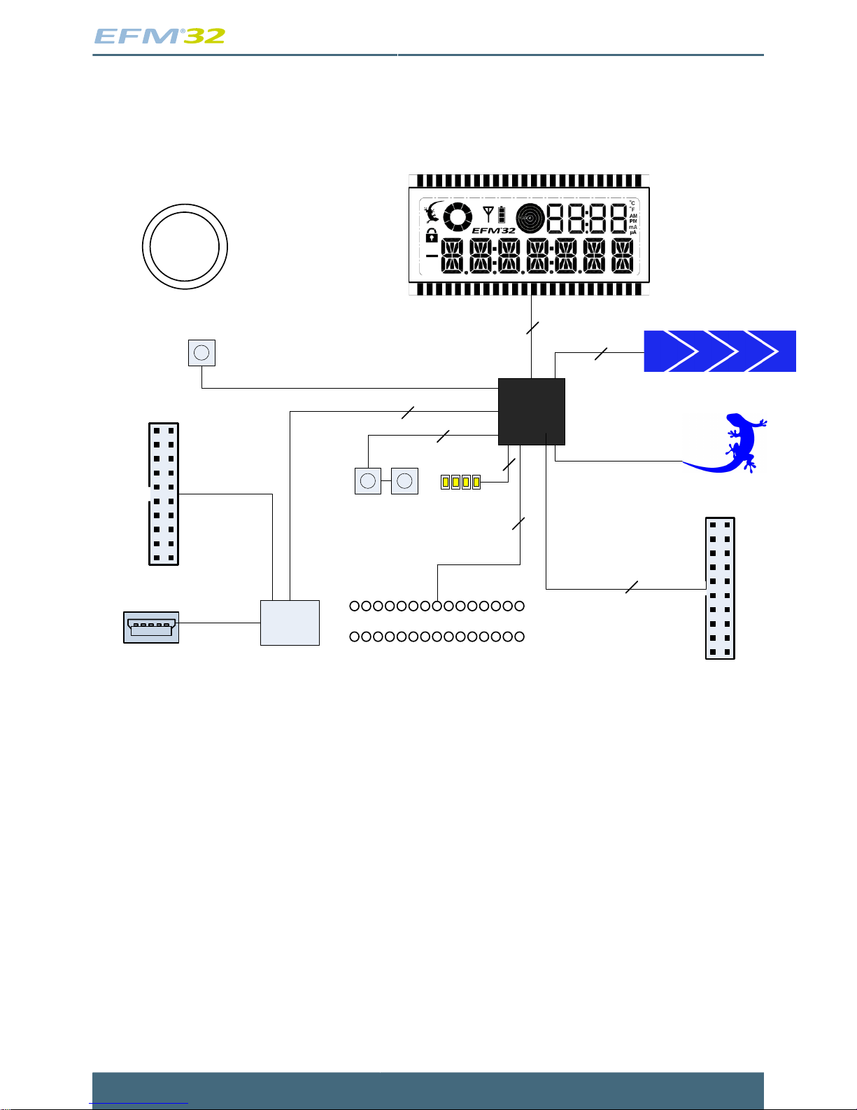
The BSP use EFM32 peripheral UART0 (TX pin PE0, RX pin PE1) on baudrate 115200-8-N-1 to
communicate with the board controller.
Note The BSP is only functional when the Starter Kit is USB-powered, using these function calls
under battery power will give unpredictable results.
9.1 Installation location
When installing the complete software package for the kit, the BSP will be installed under the main
installation directory, typically in a location such as
C:\Program Files\Energy Micro\EFM32 Gecko DK\boards\EFM32_Gxxx_STK\bsp\
or something similar (depending on your OS/Windows version). All files in the board support package
is prefixed by stk.
9.2 Application Programming Interface
To use the BSP, include the Starter Kit header file, like this:
#include "stk.h"
All functions in the BSP are prefixed with STK_. The main initialization routine is defined as
void STK_Init(void);
and must be called before any access to the STK-functions. This function call will setup the UART
communication channel with a 115800 baud rate. This baud rate depends on the current core clock, so
correct clock configuration should be set before calling this function.
bool STK_Ready(void);
Returns true if the board controller is responding. A non-responding board will either return false, or
hang (i.e. if the EFM32 is powered by the CR2032 battery cell).
float STK_Current(void);

...the world's most energy friendly microcontrollers
2010-11-12 - t0008_1.01 11 www.energymicro.com
Returns instant current usage in milliamperes.
float STK_Voltage(void);
Returns instant voltage (VMCU) reading in volt.
bool STK_EnergyMode(uint8_t em);
Informs the board controller about the Energy Mode (sleep mode) we are going into. This information
can be used by the board controller to present a richer visual graph for illustrating what the EFM32 is
currently doing.
In addition to these main functions, full documentation of the complete API is included in the Doxygen/
HTML documentation of the installed package.
9.3 Example Applications
Under the EFM32_Gxxx_STK/examples folder in your installation directory, you will find an example
program using the BSP, with corresponding project/Makefiles for the supported IDEs.
9.4 How to include in your own applications
The easiest way to include the BSP in your application is to base your work on the example application
that use the BSP. The following items are recommended for correct configuration:
1. Make sure you define the correct part number (i.e. EFM32G890F128) as a preprocessor defined
symbol
2. Make sure you define the correct part number (i.e. EFM32G890F128) for your project file
3. Add and include the EFM32_CMSIS-files (startup_efm32.s, system_efm32.c, core_cm3.c) to your
project
4. Add and include _all_ BSP package .c-files, with the stk-prefix to your project
5. Configure include paths to point at the CMSIS/CM3/CoreSupport and CMSIS/CM3/DeviceSupport/
EnergyMicro/EFM32 directories
6. Configure include paths to point to the EFM32_Gxxx_STK/bsp directory
Make sure you call "STK_Init()" early at startup, and you should be all set.
9.5 Chip errata
Early versions of the development kit are shipped with EFM32 Engineering Samples on the MCU
modules.There hasbeen updatesto configurationand resetvalues thatneeds tobe configuredcorrectly
on these early parts. We recommend always starting your application with a call to
#include "efm32_chip.h"
CHIP_Init();
in the EFM32_CMSIS (version 1.3.0 or later) core package to ensure correct and stable behavior. See
the BSP examples for details. We recommend also to download and read the latest errata from the
Energy Micro website for your part number.

...the world's most energy friendly microcontrollers
2010-11-12 - t0008_1.01 12 www.energymicro.com
10 Connectors
10.1 Breakout pads
Most I/O except the LCD pins are routed to the breakout pads at the top and bottom edge of the kit. A
2.54mm (100 mil) pitch pin header can be soldered in place on the pads for easier access.
Note Some of the breakout pads are shared by on-board EFM peripherals. The shared pins can
be identified by looking at the Shared by column in the tables below. The schematic must
be consulted to make sure that it is OK to use a shared pin in your application.
Table 10.1. Bottom breakout pad row
Pin Alternative Functions Shared by
5V - -
PA12 TIM2_CC0 LCD Boost capacitor
PA13 TIM2_CC1 LCD Boost capacitor
PA14 TIM2_CC2 LCD Boost capacitor
GND - -
PE0 U0_TX/PCNT0_S0 BC_TX
PE1 U0_RX/PCNT0_S1 BC_RX
PE2 ACMP0_O EXP header
PE3 ACMP1_O -
GND - -
PC0 ACMP0_CH0/US1_TX/PCNT0_S0 User LED 0
PC1 ACMP0_CH1/US1_RX/PCNT0_S1 User LED 1
PC2 ACMP0_CH2/US2_TX User LED 2
PC3 ACMP0_CH3/US2_RX User LED 3
PC4 ACMP0_CH4/LET0_O0/US2_CLK/PCNT1_S0 EXP header
PC5 ACMP0_CH5/LET0_O1/US2_CS/PCNT1_S1 EXP header
PC6 ACMP0_CH6/LEU1_TX/I2C0_SDA -
PC7 ACMP0_CH7/LEU1_RX/I2C0_SCL -
PC8 ACMP1_CH0/TIM2_CC0/US0_CS Touch slider segment 0
PC9 ACMP1_CH1/TIM2_CC1/US0_CLK Touch slider segment 1
PC10 ACMP1_CH2/TIM2_CC2/US0_RX Touch slider segment 2
PC11 ACMP1_CH3/US0_TX Touch slider segment 3
PC12 ACMP1_CH4/CMU_OUT0 EXP header
PC13 ACMP1_CH5/TIM1_CC0/TIM0_CDTI0/PCNT0_S0 Touch Gecko
PC14 ACMP1_CH6/TIM1_CC1/TIM0_CDTI1/PCNT0_S1 -
VMCU - -
3V3 - -

...the world's most energy friendly microcontrollers
2010-11-12 - t0008_1.01 13 www.energymicro.com
Table 10.2. Top breakout pad row
Pin Alternative Functions Shared by
5V - -
PB9 - User button 0
PB10 - User button 1
GND - -
PB11 DAC_OUT0/LET0_O0 EXP header
PB12 DAC_OUT1/LET0_O1 EXP header
PB15 - -
GND - -
PD0 US1_TX/PCNT2_S0 EXP header
PD1 TIM0_CC0/US1_RX/PCNT2_S1 EXP header
PD2 TIM0_CC1/US1_CLK EXP header
PD3 TIM0_CC2/US1_CS EXP header
PD4 LEU0_TX EXP header
PD5 LEU0_RX EXP header
GND - -
PD6 ACMP0_CH6/LET0_O0/I2C0_SDA EXP header
PD7 ACMP0_CH7/LET0_O1/I2C0_SCL EXP header
PD8 ADC0_VCM/CMU_OUT1 EXP header
PD14 I2C0_SDA -
PD15 I2C0_SCL -
VMCU - -
3V3 - -

...the world's most energy friendly microcontrollers
2010-11-12 - t0008_1.01 14 www.energymicro.com
10.2 Expansion header
A 20 pin expansion header can be used to connect plugin boards. This contains a selection of I/O plus
powers and ground. See the pinout in the table below.
Table 10.3. Expansion header pinout
I/O # # I/O
GND 1 2 VMCU
PC4 3 4 PD0
PC5 5 6 PD1
PC12 7 8 PD2
PE2 9 10 PD3
PB11 11 12 PD4
PB12 13 14 PD5
PD7 15 16 PD6
PD8 17 18 5V
GND 19 20 3V3
Table 10.4. Expansion header pin list
EXP header pin
number MCU GPIO pin MCU GPIO pin functions
1 GND Ground
2 VMCU MCU supply voltage
3 PC4 USART2_CLK #0 / LETIMER_OUT0 #3 / PCNT1_S0IN #0 / ACMP0_CH4
4 PD0 USART1_TX #1 / PCNT2_S0IN #0 / ADC0_CH0
5 PC5 USART2_CS #0 / LETIMER_OUT1 #3 / PCNT1_S1IN #0 / ACMP0_CH5
6 PD1 TIMER0_CC0 #3 / USART1_RX #1 / PCNT2_S1IN #0 / ADC0_CH1
7 PC12 CMU_CLKOUT0 #1 / ACMP1_CH4
8 PD2 TIMER0_CC1 #3 / USART1_CLK #1 / ADC0_CH2
9 PE2 ACMP0 _OUT #1
10 PD3 TIMER0_CC2 #3 / USART1_CS #1 / ADC0_CH3
11 PB11 LETIMER0_OUT0 #1 / DAC0_OUT0
12 PD4 LEUART0_TX #0 / ADC0_CH4
13 PB12 LETIMER0_OUT1 #1 / DAC0_OUT1
14 PD5 LEUART0_RX #0 / ADC0_CH5
15 PD7 LETIMER0_OUT1 #0 / I2C0_SCL #1 / ADC0_CH7
16 PD6 LETIMER0_OUT0 #0 / I2C0_SDA #1 / ADC0_CH6
17 PD8 CMU_CLKOUT1 #1 / ADC0_VCM
18 5V USB Power
19 GND Ground
20 3V3 3.3V board power

...the world's most energy friendly microcontrollers
2010-11-12 - t0008_1.01 15 www.energymicro.com
10.3 Debug connector
This connector is used for Debug In and Debug Out (see Debug chapter). The pinout is described in
the table.
Table 10.5. Debug connector pinout
Pin
number Function Note
1 VTARGET Target voltage on the debugged application.
2 NC
3 /TRST JTAG tap reset
4 GND
5 TDI JTAG data in
6 GND
7 TMS/SWDIO JTAG TMS or Serial Wire data I/O
8 GND
9 TCK JTAG TCK or Serial Wire clock
10 GND
11 RTCK JTAG RTCK
12 GND
13 TDO/SWO JTAG TDO or Serial Wire Output
14 GND
15 /RESET Target MCU reset
16 GND
17 PD This pin has a 100k pulldown.
18 Cable detect This signal must be pulled to ground by the external debugger or application for cable
insertion detection.
19 PD This pin has a 100k pulldown.
20 GND

...the world's most energy friendly microcontrollers
2010-11-12 - t0008_1.01 16 www.energymicro.com
11 Debugging
The EFM32-G8XX-STK has an on-board debugger, and it can be used in different ways to debug the
EFM, both on and off kit. Below are descriptions on the different modes. Check the configuration chapter
to find out how to change the debug setting.
Table 11.1. Debug modes
Mode Description
Debug MCU In this mode the on-board debugger is connected to EFM on the EFM32-G8XX-STK.
Debug IN In this mode the on-board debugger is disconnected, and an external debugger can be connected to
debug the EFM on the EFM32-G8XX-STK.
Debug OUT In this mode the on-board debugger can be used to debug an EFM mounted in your own application.
11.1 Debugging during battery operation
Whenthe EFMis powered by the battery (i.e. the USB isdisconnected), theon-board debug functionality
is not available. To enable debugging in this mode, connect an external debugger (e.g. another EFM32-
G8XX-STK) to the debug pads in the bottom right corner of the EFM32-G8XX-STK. These pads are
connected directly to the EFM32 debug interface.
Note When the on-board debugger is active, a current of approximately 1.6uA will be added to the
AEM measurements.

...the world's most energy friendly microcontrollers
2010-11-12 - t0008_1.01 17 www.energymicro.com
12 Integrated Development Environments
The Energy Micro software packages contains various examples in source form to use with the Starter
Kit. The following IDEs are supported.
12.1 IAR Embedded Workbench for ARM
An evaluation version of IAR Embedded Workbench for ARM is included on a CD in the EFM32-G8XX-
STK package. Check the quick start guide for where to find updates, and IAR's own documentation on
how to use it. You will find the IAR project file in the
iar
subfolder of each project
12.2 Rowley Associates - CrossWorks for ARM
See the quick start guide for download details for CrossWorks for ARM. You will find CrossWorks project
files in the
rowley
subfolder of each project.
12.3 CodeSourcery - Sourcery G++
See the quick start guide for download details for Sourcery G++. The
codesourcery
subfolder contains Makefiles for use with the Sourcery G++ development environment.
12.4 Keil - MDK-ARM
See the quick start guide for download details for evaluation versions of Keil MDK-ARM. The
arm
subfolder in each project contains project files for MDK-ARM. Please see the MDK-ARM documentation
for usage details.

...the world's most energy friendly microcontrollers
2010-11-12 - t0008_1.01 18 www.energymicro.com
13 energyAware Commander and Upgrades
energyAware Commander is a program that comes with the Gecko DK Installer package. It can perform
various kit and EFM32 specific tasks. The program has two modes of operation, either command line or
GUI mode. The command line is not backwards compatible with the earlier "Gecko Commander" shell
utility, but support all features of that package.
13.1 GUI Operation
The primary use of energyAware Commander is in the GUI mode. This utility gives the ability to program
the EFM32, upgrade the kit, lock and unlock devices and more. Some of the features will only work
with Energy Micro kits, while other will work with a J-Link debugger connected. Press the "F1" button,
or select the "Help->Help" menu item for a full description.
13.2 Command Line operation
Using the command line involves runnig the binary in a command shell, with an appropriate argument,
e.g.
eACommander.exe --help
All command line options will be parsed in the other they are given, so multiple commands can be run.
Table 13.1. energyAware Commander command line options
Option Description
--version Prints version and exits
--help (-h) Prints this help information
--flash image.bin (-f) Flash binary file to EFM32
--install package.emz (-i) Install kit firmware
--mcuinfo Print MCU information
--kitinfo Print Kit information
--usb 0-3 (-u) Specify USB address
--speed wanted speed (-s) Set SWD speed (in kHz)
--verify (-v) Verify flash after upload
--mode in|out|mcu|off (-m) Set debug mode
--unlock Unlock a locked chip
--lock (-l) Lock a chip
--reset (-r) Reset the EFM32
--unprotect Unprotect pages
--protect start stop Protect pages
--upload file Upload files to DVK
The mode option argument Sets the mode of the on-board debugger. Available modes:
mcu - Debug the EFM32 using the on-board debugger
in - Debug the EFM32 using an external debugger
out - Use the STK as an external debugger
off - Disable the debugger

...the world's most energy friendly microcontrollers
2010-11-12 - t0008_1.01 19 www.energymicro.com
13.3 Upgrades
Upgrading the kit can be done by using the "Upgrade Kit" script in the start menu. New versions
can be downloaded from http://www.energymicro.com/downloads/. The script will use energyAware
CommandertoinstallthelatestavailableKitSW package.Itisimportanttoupgrade thekitwheninstalling
a new SW package, as new energyAware Commander functionality might require kit controller software
upgrades.
You can also use the energyAware Commander for upgrades. Select the "Kit" icon, use the "Browse"
button to select the correct file ending in ".emz", and press the "Install package button".
Finally, there is an option at the command line,
eACommander.exe --install stkappl.emz
to explictly install new packages by hand (or within a script).

...the world's most energy friendly microcontrollers
2010-11-12 - t0008_1.01 20 www.energymicro.com
14 Errata
The following sections lists the erratas and known issues for operating the STK. You can read the STK
revision on the white label on the back side of the STK. It is in the format "BRD2001, Rev: Axx".
14.1 Chip errata
You can use energyAware Commander (GUI version) and press the "Connect" button to retrieve EFM32
revision information. You can also use the command line version:
eACommander.exe --mcuinfo
for the same. Download the chip errata from http://www.energymicro.com for the latest erra updates on
your device.
14.2 efm32lib Chip Init routine
The efm32lib
#include "efm32_chip.h"
CHIP_Init()
routine will, as far as possible, enable work arounds for chip erratas to make EFM32 Gecko devices
be as software compatible as possible. In some cases, this can introduce increased current. See the
device errata and source code for details.
14.3 STK Revision Errata
Table 14.1. BRD2001 Revision Errata
Revision Problem Description
A00-A05 Increased current usage The Gecko series of devices has an errata, where
going to Energy Mode 2 will drive a pull down on the
SWO (Serial Wire Output) UART serial line. This will
increase current with 80-100 uA. Work around is not
using SWO to get more accurate measurements.
Table of contents