Energy Solutions IsoBoost User manual

Energy Solutions (UK) Ltd
IsoBoost 12 kVA - US
IsoBoost 24 kVA - US
IsoBoost 24 kVA –EU
OWNERS MANUAL
v1.1
May 2019.

IsoBoost Owners and Installation Manual
2
TABLE OF CONTENTS
Introduction............................................................................................................................................................3
Safety Notices.........................................................................................................................................................4
About This Manual..................................................................................................................................................5
Model and Serial Number...................................................................................................................................5
Using this Manual ...............................................................................................................................................5
General Safety ........................................................................................................................................................6
Operating Safety.................................................................................................................................................6
Maintenance Repairs............................................................................... 6
Modifications........................................................................................... 7
Cleaning ................................................................................................... 7
Product Features ....................................................................................................................................................8
Setup and Connections...........................................................................................................................................9
Installation ..........................................................................................................................................................9
Operation..............................................................................................................................................................13
12 and 24 kVA - US............................................................................................................................................13
24 kVA- EU ........................................................................................................................................................13
Troubleshooting................................................................................................................................................14
Dimensional Drawings ..........................................................................................................................................15
IsoBoost 12 Kva - US .........................................................................................................................................15
IsoBoost 24 kVA –US and EU VERSIONS ..........................................................................................................16
Technical Data ......................................................................................................................................................17
Specifications....................................................................................................................................................17
Warranty...........................................................................................................................................................18
Declaration of Conformity ................................................................................................................................19

IsoBoost Owners and Installation Manual
3
INTRODUCTION
Dear Customer,
Thank you for purchasing an Energy Solutions IsoBoost transformer.
Energy Solutions designs and builds products to strict specifications and quality control procedures and with
proper use and maintenance this product should bring you years of satisfactory service.
We want to help you get the best results from this product and ask that you spend a small amount of time
reading this manual before operating the IsoBoost.
All information in this manual is based on the latest product information at the time of printing. Energy Solutions
reserves the right to make changes at any time without obligation.
All pictures in this manual are for reference purposes only.
This manual should stay with the unit at all times.
Figure 1 - IsoBoost 24 kVa

IsoBoost Owners and Installation Manual
4
SAFETY NOTICES
Important Information
Operator Manual
WARNING
You and others can be killed or seriously injured if you operate or maintain the unit without first studying the Owner’s
Manual. You must understand and follow the instructions in the Owner’s Manual. If you do not understand anything, ask
your supplier or Energy Solutions to explain it.
Do not operate the unit without an Owner Manual, or if there is anything on the unit you do not understand. Treat the
Owner’s Manual as part of the unit. Keep it clean and in good condition. Replace the Owner’s Manual immediately if it is
lost, damaged or becomes unreadable.
Safety Warnings
This safety alert system identifies important safety messages in this manual. When you see this symbol, be alert, your safety
is involved, carefully read the message that follows, and inform other operators.
In this publication and on the machine, there are safety notices. Each notice starts with a signal word. The signal word
meanings are given below.
DANGER
Denotes an extreme hazard exists. If proper precautions are not taken, it is highly probable that the operator (or others)
could be killed or seriously injured.
WARNING
Denotes a hazard exists. If proper precautions are not taken, the operator (or others) could be killed or seriously injured.
CAUTION
Denotes a reminder of safety practices. Failure to follow these safety practices could result in injury to the operator (or
others) and possible damage to the IsoBoost .

IsoBoost Owners and Installation Manual
5
ABOUT THIS MANUAL
MODEL AND SERIAL NUMBER
This manual provides information for the following models:
IsoBoost 12 kVA - US
IsoBoost 24 kVA - US
IsoBoost 24 kVA –EU
Although the above models differ in size, output power or output voltage form, they are otherwise similar in design and
operation. Where necessary, differences between the versions will be explained in the text and images. The serial number
can be found on the unit.
USING THIS MANUAL
This manual is arranged to give you a good understanding of the unit and its safe operation. It also contains maintenance
information and specification data. Read this manual from front to back before using the unit for the first time. Particular
attention must be given to all the safety aspects of operating and maintaining the unit.
If there is anything you are not sure about, ask your supplier.
General warnings in this chapter are repeated throughout the manual, as well as specific warnings.
The illustrations in this manual are for guidance only. Where the units differ, the text and or the illustration will specify.
All optional equipment included in this manual may not be available in all territories.

IsoBoost Owners and Installation Manual
6
GENERAL SAFETY
The following safety checklist is intended to help remind you of safety procedures and practices.
SAFETY IS YOUR RESPONSIBILITY
You must also refer to local regulations in the country your equipment is being used in. Some of the information may be
repeated in the following warnings and cautions pages and in the main text.
–Do not change the application or specification of the IsoBoost .
–Do not lift heavy objects on your own, use lifting equipment or obtain the help of an assistant.
–Use the right tools for the job.
–Always make the unit is safe before completing any maintenance tasks.
CAUTION
Injury may occur when lifting. Do not lift heavy objects on your own. Use lifting equipment or the help of an assistant.
OPERATING SAFETY
WARNING
Product Condition
A defective product can injure you or others. Do not operate an IsoBoost which is defective or has missing parts. Make
sure the maintenance procedures in this manual are completed before using the IsoBoost.
WARNING
Product Limits
Operating the product beyond its design limits can damage the IsoBoost, it can also be dangerous. Do not operate the
IsoBoost outside its limits.
MAINTENANCE REPAIRS
WARNING
If your IsoBoost does not function correctly in any way, get it repaired straight away. Neglect of necessary repairs could
cause further damage or make the unit unsafe. Do not try to do repairs or any other type of maintenance work you do not
understand. To avoid injury and/or damage get the work done by a specialist engineer.

IsoBoost Owners and Installation Manual
7
MODIFICATIONS
WARNING
This unit is manufactured in compliance with legislative and other requirements. It should not be altered in any way which
could affect or invalidate any of these requirements. For advice consult Energy Solutions.
CLEANING
CAUTION
Fully isolate the supply of power to the unit before cleaning. Clean the outside of the unit with a damp cloth. Do not spray
water into the vents.
CAUTION
Do not drop or shock the unit. Severe internal damage may occur. Do not use the unit if it has been dropped, even if it
appears to be undamaged.

IsoBoost Owners and Installation Manual
8
PRODUCT FEATURES
All versions of the IsoBoost have the following features:
•A fully isolating hand built transformer
•A soft start system to minimise the risk of tripping the shore side breaker when first connecting.
•A sophisticated control system that will automatically select between boost and straight through mode on
US versions.
•A sophisticated control system that will automatically select between buck and straight through mode on EU
versions.
•Modbus data for optional remote monitoring the IsoBoost
Three versions are currently available
•12 kVA US - A hull isolation transformer rated for a 50A 208/240V shore cord
•24 kVA US - A hull isolation transformer rated for a 100A 208/240 shore cord
•24 kVA EU - A hull isolation transformer rated for a 100A 230 shore cord or 63 amp 400 volt cord
The IsoBoost is packaged in a robust steel enclosure, powder coated for longevity. Care should be taken to lift the unit on a
pallet or by lifting from points on the transformer frame.
The IsoBoost is designed to operate automatically with no user intervention.
On the US model the IsoBoost starts in 1:1 mode. If the output voltage is below 215 volts the unit will switch to boost mode.
If the output voltage rises above 255 volts the unit will drop back to 1:1 mode.
On the EU model the control system will start the IsoBoost in 1:1 mode if the incoming voltage is between 190 and 255 volts.
The control system will start the IsoBoost in buck mode if the incoming voltage is between 340 and 440 volts.
All versions of the IsoBoost include a sophisticated multifunction meter built into the front of the case. It provides
comprehensive monitoring of the output from the IsoBoost, including voltage, current, frequency, power and more.
All versions are fitted with a cooling fan. Air is drawn in through the front of the unit below the meter, and expelled out the
rear right hand side. Do not block any cooling vents. If the fan fails, it must be replaced.
A thermal overload switch is incorporated within the transformer windings. If the transformer overheats, this will operate
and switch off the supply. Once it cools, it will reconnect. If this ever happens, check the cooling fan and seek advice. The
unit is designed and tested to work at full load in 60°C/140°F ambient conditions.
IsoBoost Owners and Installation Manual
9
SETUP AND CONNECTIONS
INSTALLATION
PLACEMENT
The IsoBoost should be fixed to a structural part of the ship that can accept the weight of the unit. It should be fixed down
using the clearance holes in its feet.
The product is heavy and suitable lifting equipment must be used. Do not attempt to lift the IsoBoost manually. The IsoBoost
will reject some heat. Do not block vents.
The IsoBoost transformer is not waterproof. Do not expose to rain or water.
PREPARING FOR INSTALLATION
Remove the front panel of the IsoBoost unit. You will need a 4mm hex (Allen) key to remove the fixings.
A removable gland plate is situated on the right hand side of the unit. This plate will need to be drilled to install cable glands
(not supplied).
ELECTRICAL CONNECTIONS
WARNING
The installation of the IsoBoost should be carried out by a qualified electrician. This unit case must be earthed in all modes
of operation.
AC INPUT
The unit should be wired to the shore supply receptacle with cable with a suitable rating to satisfy the relevant standards for
the vessel. If the IsoBoost is more than 3 metres or 10 ft from the inlet an inline circuit breaker may be required to meet
relevant standards:
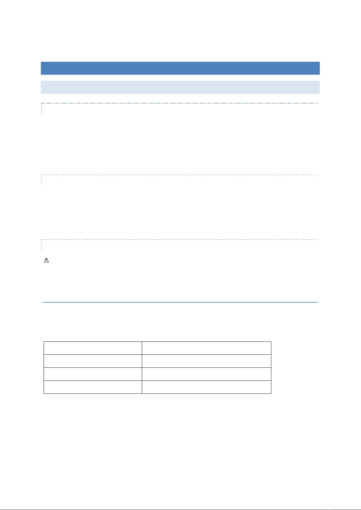
Model
Cable current
IsoBoost 12 kVA US
50A Single phase
IsoBoost 24 kVA US
100A Single phase
IsoBoost 24 kVA EU
63A in buck mode –100 amp in 1:1 mode
IsoBoost Owners and Installation Manual
10
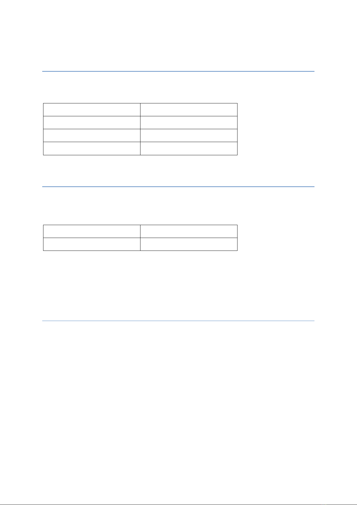
AC OUTPUT
The unit should be connected to the ships distribution system using cable with a suitable rating to satisfy the relevant
standards for the vessel:
Model
Cable rating required
IsoBoost 12 kVA US
50A
IsoBoost 24 kVA US
100A
IsoBoost 24 kVA EU
100A
OTHER CONNECTIONS
Terminals 101 and 102 are a dry contact indicating the state of boost mode.
The contact rating is 6A at 230VAC, 4A at 24VDC.
Contacts open
Passthrough mode –boost not active
Contacts closed
Boost active
Terminals A, B, and S are a Modbus RTU connection to the multifunction meter. Remote displays are available –please
contact your supplier for details. The communication protocol can be supplied upon request to allow integration into your
ships monitoring system.
EARTHING
The IsoBoost must be earthed. An earthing terminal is provided for this purpose.
The typical arrangement for an isolation transformer is as follows
•All versions - Input earth or ground (from shoreline) -connects to the interwinding screen between the input and
output windings of the transformer.
•US versions- Output earth or ground is connected to the ships earth, the case of the IsoBoost, and the centre tap
of the output winding.
•EU versions- Output earth or ground is connected to the ships earth, the case of the IsoBoost, and one pole (the
Neutral) of the output winding.
Other arrangements are possible, depending on local regulations, and the design of the boat.

IsoBoost Owners and Installation Manual
11
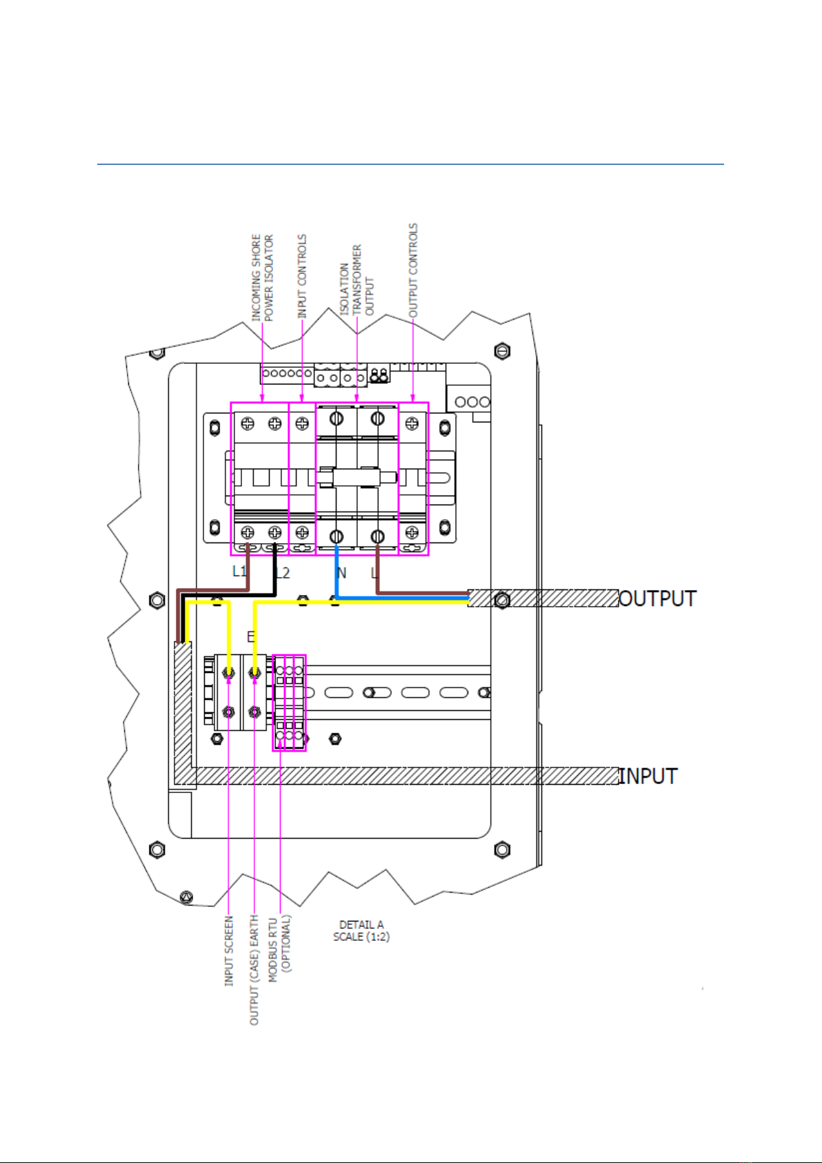
TYPICAL US CONNECTIONS (12KVA AND 24KVA VERSIONS)
When used as an Isolating Transformer, for a typically wired US boat:
Please note that the incoming Neutral (White), if present, is not required and should be safely terminated.
IsoBoost Owners and Installation Manual
12
TYPICAL EU CONNECTIONS
When used as an Isolating Transformer, for a typically wired EU boat:

IsoBoost Owners and Installation Manual
13
OPERATION
WARNING
The IsoBoost does not change the frequency of the incoming electrical supply.
If your vessel is built for 50Hz operation, do not connect it to a 60Hz supply.
If your vessel is built for 60Hz operation, do not connect it to a 50Hz supply.
Some vessels may be built to operate on either 50 or 60Hz supplies. Consult your vessel owners manual or the
manufacturer to confirm this.
12 AND 24 KVA - US
1. The shore cord of the vessel will be a 3-wire cord (2 current carrying conductors and an earth).
2. Turn off the input isolator and output breaker of the IsoBoost.
3. Plug the shore-cord into either:
4. Any two phases of a three phase 208 Volt supply –Or -
5. L1 and L2 of a US 240 Volt supply –Or -
6. L1 and N of a European 230 Volt supply (if the boat is suitable for 50Hz operation)
7. Switch on the input isolator on the IsoBoost.
8. The IsoBoost will immediately connect and soft start the transformer in 1:1 mode.
9. If the voltage is low (less than 215 volts) then, after a short delay, the IsoBoost will switch to boost mode.
10. If, during use, the voltage of the supply increases, then the IsoBoost will drop out of boost mode when the output
voltage reaches 255 volts.
11. The inbuilt display will show output volts, amps, frequency, power, energy, and more.
12. Confirm that the supply indicated on the meter is correct, and then switch on the IsoBoost output breaker.
24 KVA- EU
1. The shore cord of the vessel will be a 3-wire cord (2 current carrying conductors and an earth).
2. Turn off the input isolator and output breaker of the IsoBoost.
3. Plug the shore-cord into either:
4. Any two phases of a three phase 400 volt supply –Or -
5. Any L1 and N of a European 230 volt supply –Or -
6. Any L1 and L2 of a US 240 volt supply (if the boat is suitable for 60Hz operation)
7. Switch on the input isolator on the IsoBoost.
8. The IsoBoost will detect the incoming voltage and start in either 1:1 mode of buck mode.
9. Whichever mode is selected by the IsoBoost it will use a dedicated soft start when entering that mode.
10. If the input voltage falls outside either the low voltage range or high voltage range the unit will disconnect from
the supply.
11. The inbuilt display will show output volts, amps, frequency, power, energy, and more.
12. Confirm that the supply indicated on the meter is correct, and then switch on the IsoBoost output breaker.

IsoBoost Owners and Installation Manual
14
TROUBLESHOOTING
WARNING
If you are unsure, contact a professional electrician. Do not take risks and do not modify your IsoBoost to solve a problem.
Symptom
Suggestions
No AC power from IsoBoost
Check the INPUT ISOLATOR is on
Check the Shore Cord is correctly wired to suit the marina supply
Check that there are no tripped breakers either at the shore or on the boat prior
to the IsoBoost
Check the IsoBoost display. It should be on and showing the boat supply voltage
Check the control circuit breakers on the IsoBoost. These power the display and
the control system.
Nothing on control panel display
Backlight is off - press any button to wake it up
Input isolator is off
Control circuit breakers are off
Fuse tripped –these are located on the side panel of the unit
Output Circuit Breaker trips
This indicates an overload. Reduce the loads on the boat and reset.
For parts and service, contact your supplier. Have the model and serial number available to ensure that you
purchase the correct parts.

IsoBoost Owners and Installation Manual
15
DIMENSIONAL DRAWINGS
ISOBOOST 12 KVA - US

IsoBoost Owners and Installation Manual
16
ISOBOOST 24 KVA –US AND EU VERSIONS

IsoBoost Owners and Installation Manual
17
TECHNICAL DATA
SPECIFICATIONS
IsoBoost 12 kVA US
IsoBoost 24 kVA US
IsoBoost 24 kVA EU
Power Rating
12 kVA
24 kVA
24 kVA
Input form
Single Phase, 50 or 60Hz (no frequency conversion)
Input Voltage range
176 –255V
176 –255V
176 –255V & 340 –440V
Input connection type
L1, L2/N - Circuit breaker tunnel terminals.
Screen –M6 terminal
Output connection type
L1, L2/N - Circuit breaker tunnel terminals.
Centre Tap, Earth –M6 terminals
ModBus connection
Terminal blocks, max wire size 2.5mm2
Remote signals connection
Terminal blocks, max wire size 2.5mm2
Metering Fuses
5x20mm, 0.5A, 250VAC (2 required)
Operating temperature
-10°C to 60°C
IP Protection
IP20
Construction
Powder coated Zintec steel. RAL9016 (Traffic White)
Total size L x W x H (mm)
467*381*310
620*508*505
Approximate weight
104kg
183kg

IsoBoost Owners and Installation Manual
18
WARRANTY
Warranty Information
This product is warranted for a period of 12 months from date of purchase and applies only to the original purchaser.
The warranty only applies to defects arising from defective materials and faulty workmanship that become evident during
the warranty period and does not include consumable items.
This warranty covers replacement parts only and does include the cost of any labour. In addition, this will not apply if the
IsoBoost is found to have been subjected to misuse, abuse, used for a purpose it was not intended for or tampered with in
any way.
In the event of any failure the IsoBoost must be returned to the supplying dealer who will take the necessary action.

IsoBoost Owners and Installation Manual
19
DECLARATION OF CONFORMITY
Energy Solutions UK Ltd declares that the following products:
IsoBoost 12kVA US
IsoBoost 24kVA US
IsoBoost 24kVA EU
EMC Directive 2014/30/EU with the following harmonized standards:
EN 55014-1:2006/A2:2011
EN 55014-2:1997/A2:2008
EN 61000-3-3:2013
Low Voltage Directive 2014/35/EU with the following harmonized standards:
EN 60335-1:2012/AC:2014
EN 62109-1:2010
Restriction of the use of certain hazardous substances (RoHS) 2011/65/EU with the following harmonized
standards:
EN 50581:2012
Signed: Paul Holland
Authority: Managing Director
Date: January 2019
Table of contents
Popular Transformer manuals by other brands


Cloud
Cloud CXL-4160 installation instructions

Audio Note
Audio Note AN-S5 Owner's information manual

Omnitronic
Omnitronic ELA 100 V 2 L user manual

Shure
Shure A15BT user guide

ORTEA NEXT
ORTEA NEXT ICAR MICROmatic HP10 Series Installation, operating and maintenance manual

Monacor
Monacor FGA-22 operating instructions


