STE TVM/38-E Manual

S.T.E. S.r.l.
Via Cavour, 66 - 20865 Usmate-Velate (MI)
Tel.: 039-68.29.450 - Fax: 039-68.29.455
Cap. Soc. € 110.000 i.v. - Tribunale Monza 21325
C.C.I.A. 1086796 - Meccanogr.MI040903
C. Fisc. 06271510155 - P. IVA IT00821070968
UNI EN ISO
9001:2015
TVM 38-E INSTRUCTION MANUAL_rev4.docx
Pag. 1 di 4
MV VOLTAGE TRANSFORMERS
OUTDOOR INSTALLATION
TYPE
TVM/38-E
Installation and Maintenance Manual
Date Version Isued: Approved: Nr.
Pag.
16/09/2021 4 F.Romanenghi L.Cesari 1 di 4
20/02/2018 3 L.Cesari A. Romanenghi
31/10/2017 2 L.Cesari A. Romanenghi
24/10/2017 1 L.Cesari A. Romanenghi

S.T.E. S.r.l.
Via Cavour, 66 - 20865 Usmate-Velate (MI)
Tel.: 039-68.29.450 - Fax: 039-68.29.455
Cap. Soc. € 110.000 i.v. - Tribunale Monza 21325
C.C.I.A. 1086796 - Meccanogr.MI040903
C. Fisc. 06271510155 - P. IVA IT00821070968
UNI EN ISO
9001:2015
TVM 38-E INSTRUCTION MANUAL_rev4.docx
Pag. 2 di 4
SCOPE
This is the user’s and maintenance manual for integrators, installer and maintenance personnel of systems
based on TVM/38-E voltage transformer. Observe the provisions of local legislation regarding the competence
criteria for personnel working with or in vicinity of electrical installations.
INTRODUCTION:
Our voltage transformers are compliant with IEC 61869-3 and EN 50124-1 Standard
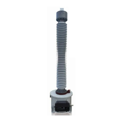
Our product model TVM/38-E is a phase-earth medium voltage transformer for outdoor installation.
RECEIPT OF THE GOODS:
On receipt of the goods, carefully verify the packing conditions and after unpacking verify the integrity of the
product. If there are damages, a claim must be raised to the forwarder. S.T.E. must be informed as well.
STORAGE:
TVM/38-E must be stored indoor, in not polluted air and with normal level of humidity between -45°C and +75°C.
INSPECTION BEFORE INSTALLATION
Before installation, transformers should be inspected for physical damage that may have occurred during
shipment or handling. Transformers should be dry and the surface of the bushings should be clean.
HANDLING AND MOVING:
Avoid any shocks. Shifting and transport must be done using lifting lugs connected to the M6x16 bolts placed in
the side of the plate (maximum torque 6 Nm). Do not move the transformer using the active parts (like
terminals or insulating silicone).
COMMISSIONING AND INSTALLATION:
SAFETY INTRUCTIONS:
The operations must be done by expert and qualified technicians, respecting the IEC standards and European
safety prescription.
ENVIRONMENTHAL CONDITIONS
Installation can be done outdoor, ambient air temperature must be included between -45°C and +75°C.
WARNING
NEVER SHORT CIRCUIT THE SECONDARY TERMINALS
INSTALLATION INSTRUCTION
Before putting in operation the voltage transformer, check the following points:
1. Always consider an instrument transformer as a part of the circuit to which it is connected, and do not
touch the leads and terminals or other parts of the transformer unless they are known to be adequately
grounded.
2. Always ground the metallic cases, frames, bases, etc., of instrument transformers. One end of the
secondary of the VT should be grounded close to the transformers. However, when secondaries of
transformers are interconnected, there should be only be one grounded point in this circuit to prevent
accidental paralleling with system grounding wires.

S.T.E. S.r.l.
Via Cavour, 66 - 20865 Usmate-Velate (MI)
Tel.: 039-68.29.450 - Fax: 039-68.29.455
Cap. Soc. € 110.000 i.v. - Tribunale Monza 21325
C.C.I.A. 1086796 - Meccanogr.MI040903
C. Fisc. 06271510155 - P. IVA IT00821070968
UNI EN ISO
9001:2015
TVM 38-E INSTRUCTION MANUAL_rev4.docx
Pag. 3 di 4
3. Check with care if both terminals of the same secondary winding are not grounded by accident. Grounding
both terminals of secondary winding can result in damage of voltage transformer over a short period of
time. Any claims for resulting transformer damages will be void.
4. Do not short circuit the secondary terminal of a voltage transformer while the transformer is energized.
Voltage transformers with secondary terminals short-circuited may be hazardous to personnel or may
damage the transformer or equipment connected in the secondary circuit. Any claims for resulting
transformer damages will be void.
5. Identify the product by the releavnt drawing/datasheet. Check the rating plate and terminal markings on
the voltage transformer and properly connect them. Check that all data indicated in the rating plate (rated
primary and secondary voltage, rated frequency, rated burden, accuracy class) have been respected.
6. Check that connections are properly performed:
a. Secondary terminals are connected to the rated load or they are not connected (open circuit).
b. All secondary windings are correctly earthed
FIXING TO THE STRUCTURE
Use the four holes on the base plate: please see the relevant drawing.
TVM/38-E voltage transformer may be mounted in vertical position only (with HV terminal of primary winding
facing the top). Other mounting positions are not allowed.
CONNECTION OF EARTH CABLE
The earth cable must be tightened up to 20 Nm between the base plate and the M8 nut placed in the base of the
transformer. The earth screw is properly marked. Remove nuts and washers, put the cable lug of the earth cable
in the screw and close by means of provided washers and nuts.
FOR SAFETY REASONS, EARTH CONNECTION MUST ALWAYS BE CONNECTED FIRST.
CONNECTION OF SECONDARY CABLE
The secondary cables must be connected to the secondary M6 terminals nuts tightening up to 2,5 Nm.
After connection of secondary cable, close the secondary terminal box with the proper red gasket and the steel
plate. The four screws must be tightened to 3Nm.
The marking of the secondary terminal is engraved inside the cover plate of secondary terminal box.
IMPORTANT: terminal of every secondary winding must be connected to ground.
The voltage transfomer must work with secondary circuit opened or loaded maximum with the rated burden
indicated on the rating plate.

S.T.E. S.r.l.
Via Cavour, 66 - 20865 Usmate-Velate (MI)
Tel.: 039-68.29.450 - Fax: 039-68.29.455
Cap. Soc. € 110.000 i.v. - Tribunale Monza 21325
C.C.I.A. 1086796 - Meccanogr.MI040903
C. Fisc. 06271510155 - P. IVA IT00821070968
UNI EN ISO
9001:2015
TVM 38-E INSTRUCTION MANUAL_rev4.docx
Pag. 4 di 4
CONNECTION OF PRIMARY BUSBAR
The primary phase cable must be tightened up to 20 Nm between the steel plate and the two M8 upper nuts
placed in the top of the transformer. Remove all nuts and washers, put the cable lug or the bar in touch with the
steel plate and close by provided washers and nuts. On the second nut, thread locking fluid (suggested Loctite
243 or Loctite 2400, or other approved by the train builder) may be applied.
Note: The voltage transformer TVM/38-E needs the flowing of only a few milliAmps of current to read the
voltage value of the primary circuit. For this reason it is designed to withstand only the static and dynamic load
of an HV flexible connection.
In case of use of a solid busbar to connect the VT to the 25 kV line, supporting insulators should be used.
POLARITY
When wiring instrument transformer circuits, it is necessary to maintain the correct polarity relationship between
the line and the devices connected to the secondaries. For this reason, the relative instantaneous polarity of each
winding of a transformer is indicated by a marker.
The primary terminals are “A” and “N” (capital letter). The secondary terminals are “a”, “n” (lowercase). The marker
“A” always indicates the same instantaneous polarity as “a”.
When connecting instrument transformers with meters, relays or other devices, refer to the instructions furnished
with the device involved.
VOLTAGE TRANSFORMER REMOVAL
In order to remove the voltage transfomer, please proceed as follows:
- Make sure that the primary circuit is disconnected from the network, and, effectively grounded
- Disconnect the the primary busbar
- Disconnect the secondary lead from the secondary terminals of voltage transformer
- Disconnect the the earthing cable
- Remove the fixing screws from the voltage transfomer plate
- Remove the voltage transformer
MAINTENANCE:
Annual check of:
- the external aspect of the voltage transformer,
- the tighten of terminals and connections
- normal cleaning of the external surface
Table of contents
Popular Transformer manuals by other brands

ABB
ABB TDO 6 Instructions for installation, use and maintenance

Conrad
Conrad 40 42 95 operating instructions
MTHTrains
MTHTrains Z-4000 operating instructions
Monacor
Monacor CARPOWER FGA-22 manual
K-Factor
K-Factor MC-TTP Series manual
Professional Pool Products
Professional Pool Products RC04 installation manual
