ENERGY SUPPORT CORPORATION DTF-201 User manual

Manual No.3156E R4
Operation Manual for
DTF-201
Oxygen Analyzer
(% Range)
RX-62230*-A*****


Observe the following cautionary items for safe operation of the device.
Warning
1. When connecting wiring at the terminal of the analyzer, be careful to avoid electric shock.
Be sure to turn the power off before connecting wiring.
2. Connect a grounding cable to avoid electric shock.
Caution
1. To avoid electric shock, check for correct power supply wiring and agreement between the
supply voltage requirement of the device and the supplied voltage before turning on the
power switch of the device.
2. Keep away from the sensor and its periphery during operation and shortly after operation
stop to avoid burns caused by high temperatures. If maintenance is inevitably necessary,
wear heat resistant gloves or the like and be careful to avoid burns.
3. An “electric shock”warning mark shown on the right is attached near the
power supply where there is a danger of electric shock. If the wiring
circuit is unknown, turn the power off even when no electric shock
warning mark is attached.
4. If the sample gas includes toxic contents, there is a danger of gas intoxication. Be sure to
shut off the source gas valve when performing maintenance of the piping system.
5. For safe and correct use of the device, observe the cautions and handling methods
described in this operation manual. If the device is operated without observing description
herein, there is a danger of electric shock, gas intoxication, oxygen deficiency and burns as
well as damage to the device, deterioration of functions or possible damage to the final
product (system, etc.).
Cautionary items for safety

1. Term
The term of guarantee of a single piece of equipment shall be one year since the product
is delivered. However, if the equipment is built in another unit, the term of guarantee shall
be that of the unit. The single unit delivery meant that the receiver, sensor unit, cable are
delivered as single unit whereas the equipment built in another unit meant the equipment
by combining the sampling flow or to combine to another units are delivered as built-in
delivery.
2. Conditions
The delivered product shall be exchanged or repaired free of charge if it fails or any
abnormality is generated due to poor workmanship in design, manufacture or material
attributable to ENERGY SUPPORT CORP. in the above-mentioned term of guarantee
though it is operated properly after it is stored and installed properly after it is delivered to
the client.
The proper operating method includes the following.
①The installation conditions and operation conditions described in the specifications of
this measuring tool and this operation manual are satisfied.
②The analyzer is periodically calibrated and replacement of consumable parts is made.
③Periodic maintenance and inspection are made according to the operating state of the
analyzer.
However, the following cases shall be excluded from the scope of guarantee even if they
occur in the above-mentioned term of guarantee.
1) Failure generated due to operation errors (erroneous operation not described in
operation manual)
2) Failure caused by repairs, remodeling, disassembly, cleaning and so on made by
other than us
3) Failure caused by fire or act of God (including inductive lightning surge)
4) Failure caused by improper storage (storage in a hot and humid site, etc.) or lack of
maintenance (generation of fungi, etc.)
Note) Consumable parts and consumable components are excluded from the scope of
guarantee.
3. Scope
The scope of guarantee shall be limited to the range delivered by us.
4. Indemnity
We will not assume responsibility for any accompanying losses caused by the failure of
our product (losses, lost profits and so on caused by the controlled or recorded results
made under the use of our product, or losses, lost profits and so on caused by the
system in which our product is installed.). Safety units or the like shall be installed under
the responsibility of the client.
5. Term of supply of replacement parts or repair
①Repairs or replacement with alternative product will be made with charge for seven
years after manufacture of the product is stopped.
②We may reject even charged repairs of products passing 10 years or more after
delivery.
Guarantee

Table of Contents
1. Introduction-----------------------------------------------------------------------------------------------------------------1
1-1 Introduction--------------------------------------------------------------------------------------------------------1
1-2 Usage Caution Notices-----------------------------------------------------------------------------------------1
1-3 Product Outline---------------------------------------------------------------------------------------------------1
1-4 Name of each part-----------------------------------------------------------------------------------------------4
2. Opening the Packaging-------------------------------------------------------------------------------------------------5
2-1 Checking the Components and Accessories-------------------------------------------------------------5
2-2 Temporary Product Storage ----------------------------------------------------------------------------------5
3. Installation------------------------------------------------------------------------------------------------------------------5
3-1 Installation Conditions------------------------------------------------------------------------------------------5
3-2 Installation Method ----------------------------------------------------------------------------------------------6
3-3 Piping and Wiring Methods------------------------------------------------------------------------------------6
4. Operation-------------------------------------------------------------------------------------------------------------------8
4-1 Operation Preparation------------------------------------------------------------------------------------------8
4-2 Start-up-------------------------------------------------------------------------------------------------------------9
4-3 Stop Procedure------------------------------------------------------------------------------------------------- 10
4-4 Procedure During Operataio-------------------------------------------------------------------------------- 10
4-5 Operation for when an Error Occurs---------------------------------------------------------------------- 18
4-6 Applied Operations-------------------------------------------------------------------------------------------- 19
5. Maintenance------------------------------------------------------------------------------------------------------------- 22
5-1 Daily and Periodic Inspection------------------------------------------------------------------------------- 22
5-2 Troubleshooting------------------------------------------------------------------------------------------------ 23
6. Reference Material----------------------------------------------------------------------------------------------------- 25
6-1 Standard Specifications-------------------------------------------------------------------------------------- 25
6-2 Drawing name: DTF-201 oxygen analyzer receiver -------------------------------------------------- 26

1
1. Introduction
1-1 Introduction
The DTF-201 Oxygen Analyzer is a product of the latest ceramics production technology,
using a thick film sensor and digital signal processing technology. This Operation Manual
explains how to operate the DTF-201 oxygen analyzer.
Please read this manual thoroughly to ensure long, successful operation of your
SH-201-C Oxygen Analyzer.
1-2 Usage Caution Notices
・Do not install the analyzer in a location subjected to vibration.
・Do not apply water or volatile fluids to the analyzer.
・Do not use sample gas containing corrosive gases (F, HF, CL2, HCL, SO2, H2S, etc.)
or poisonous materials (Si, Pb, P, Zn, Sn, As, etc.). These can shorten the life of the
sensor.
・Do not use sample gas containing inflammable gas. The inclusion of inflammable gas
can cause deviation in the oxygen concentration measurement value.
・The major usage of this oxygen analyzer is for atmospheric oxygen measurement at
boiler, Heating furnace.
・
1-3 Product Outline
The DTF-201 oxygen analyzer has the following features.
・With one calibration of the air sample point is possible.
・Compact size.(Small installation space.)
・Easy maintenance.
・Low power consumption by the sensor.(About 13 W for normal use.)
・Short warm up time.
・No power switch.

2
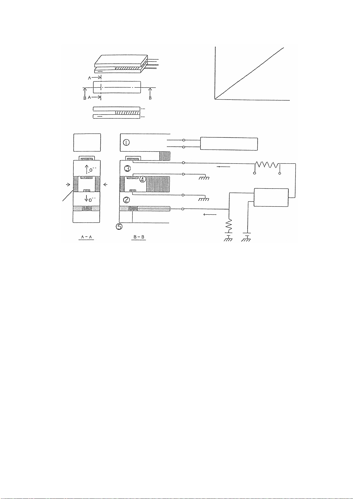
Operating Principles of Zirconia Type Oxygen Analyzer
(1) Configuration and Functions (See diagram at right.)
Heater: Heats the sensor to approximately 800℃.
Sensing cell: Sets the oxygen concentration of the reference oxygen
chamber to 100%, and measures the oxygen
concentration of the gas detection chamber.
(See below for detailed principles.)
Pumping cell: Sets the oxygen concentration of the gas detection
chamber to 0%.
(See below for detailed principles.)
Gas detection chamber: Inducts gas through the gas diffusion holes.
Reference oxygen chamber: The oxygen concentration is set at approximately
100% by the reference oxygen microcurrent.
(2) Detection characteristics resulting from high temperature heating of the sensor:
When a gas with a different oxygen concentration is put between the electrodes,
oxygen ion conductivity occurs and electromotive force is generated. (Oxygen
concentration cell effect)
When current is applied between the electrodes, oxygen ions flow in the opposite
direction in proportion to the current. (Oxygen pumping effect)
The sensing cell uses characteristics and above, and the pumping cell uses
characteristic above.
(3) Sensing Cell Principles
Minute current flows between the electrodes of the sensing cell. When current is
applied between the electrodes, the oxygen inside the gas detection chamber is
transferred to the reference oxygen chamber so that the oxygen concentration in the
reference oxygen chamber is approximately 100%.
Note: The quantity of oxygen transferred from the gas detection chamber to the
reference oxygen chamber is extremely small, so it does not affect the oxygen
concentration in the gas detection chamber.
The electromotive force in the following equation is generated between the
electrodes of the sensing cell by the difference between the oxygen concentration in
the gas detection chamber and the reference oxygen chamber.
The sensing cell measures the electromotive force generated between its electrodes
and sends signals to the pumping cell so that the electromotive force reaches 450
mV (oxygen concentration of 0% in the gas detection chamber).
oxygen concentration in gas detection chamber
oxygen concentration in reference oxygen chamber (100)
X
100
X = approx. 0.003 ppm ≒0%
(4) Pumping Cell Principle
The pumping cell receives the signal from the sensing cell and applies current to the
electrodes so that the oxygenconcentration in the gas detection chamber reaches 0%.
The current applied and the oxygen concentration in the sample gas are proportional, so by
measuring the currenttheoxygen concentrationin the sample gas can be measured.
Electromotive force E = -53.2 X log 10
450 = -53.2 X log10
3
Sensor Element Construction
Heater
Sensor
Pumping current
(mA)
Exhaust gas O2concentration (%)
Gas
Gas diffusion
holes
Gas
Heater
Pumping cell
Gas detection
chamber
Sensing cell
Reference oxygen chamber
Heater temperature
control
Pumping current
Output
signal
Pumping
current
controller
Microcurrent to
generate
reference oxygen
Reference voltage
(450 mV)

4
1-4 Name of each part
(1)DTF-201 receiver of oxygen analyzer
No.
Name (function)
①
POWER lamp (Lit after the power is turned on.)
②
Display 1 (5 digits, for display of concentration, data and error)
③
Display 2 (3 digits, for display of range, concentration alarm and channel)
④
% range lamp (Lit in % measurement mode.)
⑤
ppm range lamp (Lit in ppm measurement mode.)
⑥
Key (for calibration and data setting)
⑦
Installation fitting (for fixing the panel)
⑧
Connector 1 (for connecting the sensor unit)
⑨
Connector 2 (for RS232C connection; option)
⑩
Terminal block (for input/output wiring)

5
2. Unpacking
2-1 Checking the Components and Accessories
Part name
Part No.
Q'ty
Remarks
Oxygen analyzer
RX-62230*-A*
1
RX-622300:AC100V
RX-622301:AC200V
RX-622303:DC24V
Installation fitting
CA-1
2
Accessory
NOTE)
※refer to your specifications document. The probe, sensor, relay cables, and others are
different depending on the specifications; check those parts off against the specifications
document.
2-2 Temporary Product Storage
When storing the product temporarily prior to installation, observe the following conditions.
・It is preferable to store the product inside a box, protected by polystyrene, etc.
Store the product in a location with the following features:
・Away from direct sunlight.
・The ambient temperature is between -10℃and 50 ℃, with little variation in temperature.
・There is little humidity and dust.
・The location is not exposed rainfall.
・There is little mechanical vibration.
・There are no corrosive gases or dangerous gases.
3. Installation
3-1 Installation Conditions
This oxygen analyzer must be installed indoors. For safe, correct use of your oxygen
analyzer, install the analyzer in a location with the following conditions to provide the best
possible installation conditions.
・There is little vibration.
・It is not affected by corrosive gases (F, HF, CL2, HCL, SO2, H2S, etc.), and will not
interfere with maintenance personnel.
・Condensation is not caused by sudden temperature fluctuations.
・It is not affected by direct heat radiation.
・It is affected little by noise.
・There is little humidity and dust.
・The ambient temperature is between 0℃and 50℃. (not exposed to direct sunlight)

6
3-2 Installation Method
Installation Cautions
・This oxygen analyzer is a precision instrument. When installing it, avoid large shocks
and applying a load upon it.
・Its terminal block and connector jut out from the panel, so they are easily damaged.
Take care not to knock them during installation.
3-3 Piping and wiring Methods
(1) Piping Arrangement
Piping between the probe generator (sensor) and the air selector unit (for supplying
calibration gas) must be connected.
Pipes consist of the following:
・Calibration gas pipe
・Ejector air pipe
・Purge air pipe
And others
Details differ depending on the specifications. Refer to your specifications document.
(2) Wiring Methods
①Wiring between the probe generator (sensor) and analyzer
Connect the sensor and analyzer with the special relay cable.
Details differ depending on the specifications. Refer to your specifications document.

7
②Wiring to receiver
Connect wiring to the receiver at the terminal block (M3 screws). Take care of the
polarity when wiring.
Layout of terminal block and description
IN1 :NO-voltage contact input terminal 1
IN2 :NO-voltage contact input terminal 2
IN3 :NO-voltage contact input terminal 3
COM1 :Common terminal for IN1 through 3
RY1 :Open co output terminal 1 (permissible rating DC25V, max.50 mA)
RY2 :Open co output terminal 2 (permissible rating DC25V, max.50 mA)
RY3 :Open co output terminal 3 (permissible rating DC25V, max.50 mA)
RY4 :Open co output terminal 4 (permissible rating DC25V, max.50 mA)
COM2 :Common terminal for RY1 through 4
OUT1+,- :4 to 20 ma DC output of oxygen concentration (corresponding to selected
range). Non-insulated output, load resistance 600 Ωor less
OUT2+,- :0 to 5 VDC output of oxygen concentration (corresponding to selected
range). Non-insulated output, load resistance 10 KΩor above
FG :Terminal for connecting shields of OUT1 and 2
POWER :Power terminal (85 to 132 VAC, 50/60 Hz, max.50 VA)
E :Grounding terminal
※1 IN1-2, RY1-4, and OUT2 are different depending on the specifications; check those
parts off against the specifications document.
※2 OUT2 is either one of DC 0-1 V, DC 0-5 V, DC 0-10 V. Refer to your specifications
document.
※3 POWER is either one of AC 85-132 V, AC 170-264 V, DC 24 V. Refer to your
specifications document.
Example of Wiring Circuit to RY
IN1 IN2 IN3 RY1 RY2 RY3 RY4COM1 COM2
OUT1
+
OUT1
-
OUT2
+FG POWER POWER E
OUT2
-
RY
COM2
R1
DC or AC
R1
DC25V 50mA以下
異常ランプ等
DC 25 V,50 mA or less
Error lamp
8
4. Operation
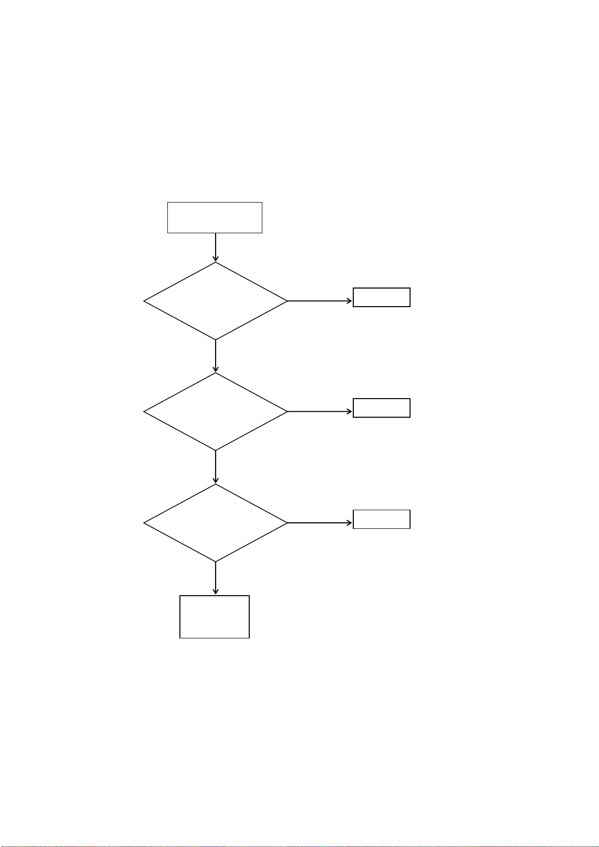
4-1 Operation Preparation
Before you turn the power ON, perform the following inspection.
Start pre-operation
inspection
Connect it.
pre-operation
inspection
completed
Is the power cord
connected properly?
Is the connecting cable
connected properly?
NO
Is the analyzer
input/output wiring
connected properly?
YES
YES
YES
Connect it.
Connect it.
NO
NO
Is the sample gas
piping connected
properly?

9
4-2 Start-up
Perform the basic start-up operation as follows.
①When you turn ON the power to the analyzer, the
POWER LED lights up and Display 1 starts the
countdown. After 3 minutes, measurement can start.
Display 1 displays the countdown as follows.
3.00 -> 2.59 -> ... -> 0.01 -> 0.00 ->
Concentration display
The analyzer does not have a power switch, so provide
one externally.
②Display 2 displays the output range No.
When range No. 1 is selected: 1
When range No. 2 is selected: 2
When range No. 3 is selected: 3
When range No. 4 is selected: 4
Checking and changing of each range is performed using
the receiver setting data (CH030 - 037).
If the concentration warning is output, the range No. is
not displayed, and AH (concentration high) or AL
(concentration low) is displayed.
For details, see page 16, 4-4 Procedure During
Operation, (2) Output Range Switching.
③For gas calibration, see page 16, 4-4 Procedure During
Operation, (4) Gas Calibration.
O2 ANALYZER
ppm
%
O2
Vol
POWER
Display 1
Display 2
ENT
RANGE
Start-up operation
Turn power ON.
Check/change
Output range.
Gas calibration
Measurement
10
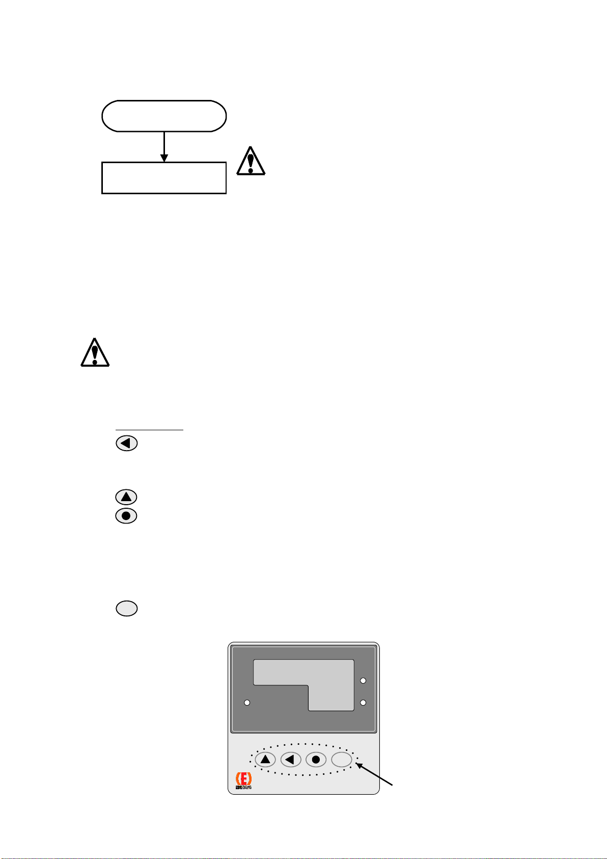
4-3 Stop Procedure
Turn OFF the power supply to the oxygen analyzer.
There is no power switch on the analyzer, so turn off the
external power supply.
If operation is stopped for a short period such as 1 week or less, do not turn off the power.
If operation is stopped for a longer period, once the sample gas is replaced by ambient air,
then turn off the power.
4-4 Procedure During Operation
(1) Key Operation Method
Key operation is required to change the range and perform gas calibration when starting
up. This operation is very important, so be sure to read these instructions.
Key operation may change the oxygen analyzer output, so when using the oxygen
analyzer output signals for control purposes, always apply the control release device
before operating the keys.
Key Functions
key …Press this key to shift from the O2Concentration display to the data
setting mode, or to move toward the left digit of the setting data. The
currently changeable digit flickers.
key …Press this key to change the value of the set CH and the set data.
key …Press this key in the following cases.
*To insert a decimal point after the flickering digit.
*To switch to the opposite sign when the set data has a plus or minus sign.
*To return to the O2Concentration display mode from the setting mode
*To clear an error when it has occurred.
key …Press this key to save data in the receiver memory after changing the
value of the set CH or set data.
ENT
Stop Procedure
Turn OFF the power
O2 ANALYZER
ppm
%
O2
Vol
POWER
Key
ENT
RANGE

11
Key Operation Method
Display 1 is the O2Concentration display.
Display 2 is the Range or Concentration warning display.
①First, press the key.
Display 2 will display the CH No. and LED 8 will flicker.
Display 1 display the data.
②Press or to set the CH No. of the data you
wish to display on Display 2.
③Press .
LED5 on Display 1 will flicker.
Display 2 will continue to display the CH No.
④Press or to change the data displayed on
Display 1.
⑤Press to save the data in the receiver memory.
⑥Press to return to the O2Concentration display.
Key operation is finished.
Using steps ①- ⑥above, you can change the range and
perform gas calibration.
The following page displays the System Data Table
explaining which data is input to which CH.
Press or
Press
Press
Key Operation Method
During measurement
Press
ENT
Press
ENT
During measurement
Press or
ENT
ENT
O2 ANALYZER
ppm
%
O2
Vol
POWER
LED
1
LED
2
LED
3
LED
4
LED
5
LED
6
LED
7
LED
8
Display 1
Display 2
Keys
ENT
RANGE
12
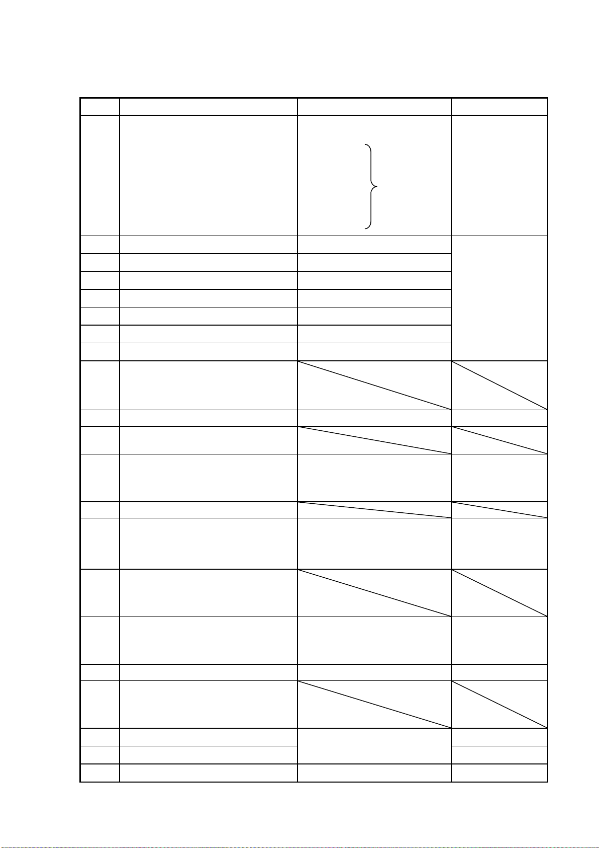
System data Table
CH No.
Function
Setting Data
Default Data
000
Display selection
0: No display (--――)
1: Oxygen concentration
2: Icp
3: Vs
4: Ip1 *2 –9 are for
5: Ip2 checking use
6: Vp by we.
7: Vh
8: Ih
9: CPU Ih
1
001
Sensor output VS monitor (V)
-
Monitor value
002
Sensor output IP monitor (A)
-
003
Sensor output IP monitor (A)
-
004
Sensor output VP monitor (V)
-
005
Sensor heater voltage monitor (V)
-
006
Sensor heater current monitor (A)
-
007
Sensor heater current monitor (A)
-
008
|
015
Data for setting, checking by
ENERGY SUPPORT CORP.
016
Primary delay time (sec)
0 –99
0
017
Data for setting, checking by
ENERGY SUPPORT CORP.
018
WET/DRY operation
0: WET
1: DRY(gas fuel)
2: DRY(solid and liquid fuel)
See
Specifications
Manual.
019
020
Output range switching
1: No. 1 range
2: No. 2 range
3: No. 3 range
4: No. 4 range
Data is supplied
for the current
selected range
021
|
022
Data for setting, checking by
ENERGY SUPPORT CORP.
023
Output hold setting
0: No hold
1: Desired value
2: Value 5 sec. before error
See
Specifications
Manual.
024
Output hold value setting (%FS)
0 - 100
0
025
|
026
Data for setting, checking by
ENERGY SUPPORT CORP.
027
OUT1 output adjustment
When adjusting output ZERO or
SPAN, sets to this CH.
-
028
OUT2 output adjustment
-
029
-
-
-

13
CH No.
Description
Setting data
Initial data
030
Output range No. 1 span value
1 - 99999
* Check the output range unit
using CH034 - 037.
See
Specifications
Manual.
031
Output range No. 2 span value
032
Output range No. 3 span value
033
Output range No. 4 span value
034
Output range No. 1 unit
0: Not in use
1: ppm
2: %
1
035
Output range No. 2 unit
1
036
Output range No. 3 unit
2
037
Output range No. 4 unit
2
038
-
-
-
039
-
-
-
040
|
119
Data for setting, checking by
ENERGY SUPPORT CORP.
120
Zero gas concentration (%)
0.00 - 99.90
See inspection
data
121
Span gas concentration (%)
122
-Span gas concentration (%)
-99.90 - 99.90
123
Air point concentration
0.00 - 99.90
125
to
142
Data for setting, checking by
ENERGY SUPPORT CORP.
143
Linearization table
Specific values for each sensor
See inspection
data
144
|
179
Data for setting, checking by
ENERGY SUPPORT CORP.
180
Calibration point selection
5: Zero point
6: Span point
8: Air point
8
181
Calibration start
0: Default value
1: Calibration start
0
182
|
189
Data for setting, checking by
ENERGY SUPPORT CORP.
190
Heater control mode
0: Heater OFF
1: Constant voltage control
2: Constant resistance control 1
3: Constant resistance control 2
1
(Change not
possible.)
191
Heater voltage setting value (V)
5.00 - 11.00
10.50
(Change not
possible.)
192
Heater resistance at room
temperature (Ω)
Specific values for each sensor
See inspection
data
193
Resistance ratio
Specific values for each sensor
See inspection
data
194
to
199
Data for setting, checking by
ENERGY SUPPORT CORP.

14
CH No.
Description
Setting data
Initial data
200
Contact output RY1 function setting
0: No contact output
1: Analyzer error
2: Range echo (2 range
discrimination)
3: Range echo (discrimination of 3
ranges or more))
4: READY
5: Concentration max. alarm
6: Concentration min. alarm
7: Range echo (3 contacts)
See
Specifications
Manual.
201
Contact output RY2 function setting
202
Contact output RY3 function setting
203
Contact output RY4 function setting
204
Contact output RY1 movement
setting
0: NO
1: NC
See
Specifications
Manual.
205
Contact output RY2 movement
setting
206
Contact output RY3 movement
setting
207
Contact output RY4 movement
setting
208
Contact input RY1 movement
setting
0: Not in use
1: Air 1 point calibration start
See
Specifications
Manual.
209
Contact input RY2,3 movement
setting
0: Local range switching
1: Remote range switching
210
|
219
Data for setting, checking by
ENERGY SUPPORT CORP.
220
O2 concentration max. alarm
setting value
0.0 - 9999.0
If 5 and 6 are set
for CH200 –
203, set your
desired limit
221
O2 concentration max. alarm
setting value
0.0 - 9999.0
222
Oxygen max. alarm unit
0: Not used
1: ppm
2: %
223
Oxygen min. alarm unit
224
Simulation output selection
0: Measurement value output
1: Simulation output
0
225
OUT1
Current simulation output value
0.0 –100.0
0.0
226
OUT2
Voltage Simulation output value
0.0 –100.0
0.0
227
|
229
Data for setting, checking by
ENERGY SUPPORT CORP.
230
Gas fuel CO2 concentration
0.00 –100.00
0.00
231
Gas fuel CO concentration
0.00
232
Gas fuel H2 concentration
0.00
233
Gas fuel CH4 concentration
0.00
234
Gas fuel C2H6 concentration
0.00
235
Gas fuel C3H8 concentration
0.00
236
Gas fuel C4H10 concentration
0.00
237
Gas fuel C5H12 concentration
0.00
238
Gas fuel N2 concentration
0.00
239
Gas fuel H2O concentration
0.00
240
Gas fuel CO2 concentration
0.00
241
Solid and Liquid fuel
C concentration
0.00
15
Caution notices when changing data settings.
Do not make changes to CH190 –191. It will change the heater voltage supplied
to the sensor, which could damage the sensor.
CH No.
Description
Setting data
Initial data
242
Solid and Liquid fuel
H concentration
0.00 –100.00
0.00
243
Solid and Liquid fuel
S concentration
0.00
244
Solid and Liquid fuel
N2 concentration
0.00
245
Solid and Liquid fuel
H2O concentration
0.00
246
Solid and Liquid fuel
O2 concentration
0.00
247
|
269
-
-
-
270
How to calibration
0: Manual
1:Semi Auto
2: Auto
276
Calibration mode
0: Air 1 point calibration
1: Air,Zero 2 point calibration
2: Air,Span 2 point calibration
3: Air,Zero,Span 3 point calibration
See
Specifications
Manual.
271
|
289
Data for setting, checking by
ENERGY SUPPORT CORP.
290
Communication setting
0: Maker setting
1: Maker setting
2: RS-232C
3: Maker setting
Option
291
Bit rate setting
0: 1200
1: 2400
2: 4800
3: 9600
292
Data length setting
0: 8 bit
1: 7 bit
293
Parity setting
0: Even parity
1: Odd parity
294
Parity mode setting
0: No check
1: Check used
295
Stop bit length setting
0: 1 bit
1: 2 bit
296
|
309
-
-
-
310
Data setting change password
0: Data change prohibited
201: Data change possible
201
Table of contents
Popular Analytical Instrument manuals by other brands


Rothenberger Industrial
Rothenberger Industrial RO-LASERMETER 35 operating manual

Digitimer
Digitimer DS4 Operator's manual

Goldanalytix
Goldanalytix GOLDSCREENPEN instruction manual

ennoLogic
ennoLogic eD560L user manual

Acuity
Acuity AR2000 Series Installation, operation and specification manual

Powerfix Profi
Powerfix Profi PEK 2.3 A1 User manual and service information


