EnerSys OLDHAM GT User manual

1
G
GT
T
&
&
G
GS
S
C
CA
AP
P
L
LA
AM
MP
P
S
SY
YS
ST
TE
EM
M
WARNING
This manual, including the warnings and cautions inside, must be read and followed carefully by all
persons who use or maintain this product, including those who have any responsibility involving its
selection, application, service, or repair. This cap lamp system will perform as designed only if used and
maintained according to the instructions, otherwise it could fail to perform as designed and persons who
rely on this product could sustain serious personal injury or death.
The Powerful Choice
INSTRUCTION
MANUAL
2
G
GT
T
&
&
G
GS
S
C
CA
AP
P
L
LA
AM
MP
P
S
SY
YS
ST
TE
EM
M
TABLE OF CONTENTS
Important p3
General description p3
Preparation for use p3
Battery charging p3
Storage of batteries p3
Filling battery p3
Cap lamp system p4
Replacing battery p4
Removing cable from battery p4
Replacing battery cover (metal) p4
Using GT & GS cap lamp systems p5
Repairing the headpiece p5
Replacing bulbs p5
Removing the bezel ring p5
Replacing main bulb p5
Replacing secondary bulb p6
Replacing the reflector p6
Reassembling the bezel ring p6
GT & GS diagram – Item list p7
Troubleshooting p8
Certification, equipment marking and instructions for p9
compliance with ATEX standards:-
Use of Equipment p10
Partsdiagram p11
3
IMPORTANT
Pay close attention to Warnings and Cautions in
this manual. A WARNING describes a condition
that may cause severe personal injury or death if
allowed to happen. A CAUTION describes a
condition that may cause moderate injury or
property damage if allowed to happen.
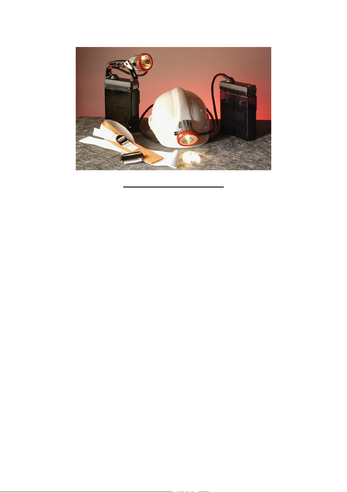
GENERAL DESCRIPTION
The GT & GS cap lamp systems consists of a cap
mounted headpiece powered by a (lead-acid)
battery.
The basis of the headpiece in which some of the
internal connections are integral is as follows. A
selector switch is incorporated, which can switch
on either the large main bulb or the small
secondary bulb. The main bulb is held in the
reflector in a focused position by a screwed bush
from which a lead connects to one of the cable
termination points. The small bulb holder is
positioned at the top of the headpiece, being
connected internally to the cable termination. The
reflector fits over the small bulb and has a rubber
gasket around the rim to seal against the
headpiece lens.
PREPARING THE GT or GS CAP LAMP FOR
FIRST TIME USE
Battery charging
Every battery must be charged before it is used
for the first time.
1. Allow the battery to remain on charge for 24
hours.
2. Top off each cell with distilled water if
necessary (see filling battery). Never fill over
top of fill line.
Note:
Batteries which do not perform satisfactorily,
should be removed from service and cycled-
charged for 16 hours and discharged 8 hours.
Repeat several times until battery responds. If
battery does not respond after three or four
cycles, it should be replaced.
Never discharge completely!
3. After weekly shifts, the battery should be
placed on the charger following the
instructions included with the charger, and left
to charge the remainder of the weekend.
4. If cap lamp needs cleaning, use a mild
detergent and wipe. Do not submerge in
water.
Storage of batteries
All stored batteries with acid should be boost
charged for 24 hours every 3 months, and
immediately before being placed into regular
service.
Recommended storage temperature: 0oC to 27oC.
Filling battery (Type T5 only)
The electrolyte level should be maintained
between the two lines below the filling and venting
hole i.e. slightly above the top of the battery plate.
Normally topping up should not be necessary
more often than once every 4-6 weeks, and
should always be carried out when the battery is
fully charged. Only distilled or de-ionized water
should be used in topping off.
WARNING
The electrolyte level of all batteries should be
checked once each week, and after the battery
is charged (T5 battery only).
Water only when battery is fully charged. If the
battery is overtopped, there is a possibility
that electrolyte may leak out under certain
conditions.
Topping up
1. Fill the plastic bottle (P/N 651901) with
distilled or de-ionized water only.
2. Insert the nozzle of the filling tube into the
small hole provided in the battery window and
squeeze the bottle gently.
3. Fill until the electrolyte level is level with the
bottom one of the two scribed lines below the
cell window. The battery may have to be tilted
back slightly to allow the water to flow.
4. Repeat this procedure in adjacent battery cell.
CAUTION
The electrolyte is corrosive and can cause
burns. Take proper precautions to avoid skin
and eye contact.

4
CAP LAMP SYSTEM
Replacing battery (Stainless steel cover)
1. To remove battery cover, remove the wax
seal (if applicable) from the lock screw hole.
2. Remove locking clamp hex screw with Allen
key (P/N 259442).
3. Remove locking clamp.
4. Lift up locking clamp end of cover and slide
cover back and off battery.
5. Remove fuse.
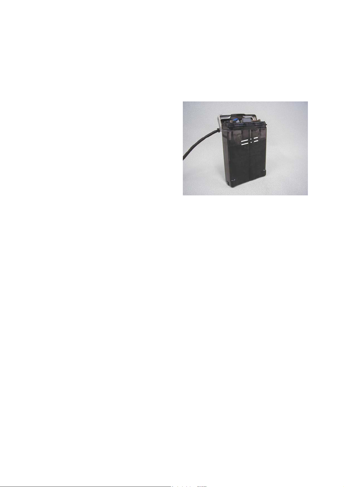
Replacing battery (Plastic cover)
1. Remove the two M4 button head socket
screws from the two clamp holding the cover.
2. Un-clip the clamps and lift cover to one side.
3. Remove fuse.
S8 plastic cover.
1. Remove the two M5 socket head screws from
the plastic cable clamp.

5
2. Lift the cable clamp to one side.
3. Remove fuse.
Removing cable from battery
1. Loosen nuts from each terminal of battery (do
not lose the nuts).
2. Lift each lead from battery terminal.
Replacing battery cover
1. Attach cable (leads) to battery
2. Connect brown conductor to positive battery
terminal.
3. Connect blue conductor to negative battery
terminal to ensure correct polarity.
4. Tighten cable leads down with terminal nuts
(do not over tighten).
5. Replace fuse.
6. Turn battery so the vent holes are facing you.
7. Replace the battery cover.
Note:
Ensure that the cable leads lie properly on the
battery top without being trapped or pinched.
USING THE GT or GS CAP LAMP SYSTEM
The GT and GS headpiece is made up of the
lamp-housing which contains the following parts:
- Bezel (ring)
- Lens (glass)
- Gasket
- Reflector
- Main bulb
- Secondary bulb
The on-off switch knob is located on the
headpiece. To operate the lamp:
1. Turn the switch knob clockwise to main bulb
or anti-clockwise to secondary bulb.
2. After use turn the switch knob until both bulbs
are off.
Repairing the headpiece
Only the small insulated screwdriver (P/N 201042)
should be used as this allows the screws to be
secured tightly enough without fear of a short-
circuit or other damage. The switch should be
placed in the off position and the battery fuse
removed (see section cap lamp system) before
dis-assembly of the headpiece. When
reassembling the headpiece ensure that the
gasket is correctly fitted around the reflector. The
location of the reflector is by two projections which
fit either side of the pin that rests against the
envelope of the pilot bulb. The bezel ring should
be screwed down firmly and the lock pin placed so
that it fits into one of the recesses of the bezel ring
and firmly screwed tight.
The lock screw can be sealed with wax – if
applicable.
WARNING
It is essential that all contacts in the headpiece
are tight, so that no electrical resistance is
incurred which might increase the time
necessary to obtain an efficient charge or
might reduce the light output of the lamp. In
order to obtain the maximum light possible,
the outside of the lens glass should be
cleaned thoroughly.
REPLACING BULBS (MAIN AND SECONDARY
BULB)
Removing the Bezel ring
1. Remove wax seal (if applicable) from lock
screw.
2. Unscrew lock screw by using special Allen
key P/N 237642
3. Unscrew and remove bezel ring from
headpiece housing.
4. Remove glass (lens) and reflector with sealing
channel from headpiece housing.
Note:
Inspect all parts for cracks or other damage.

6
Replacing the main bulb
1. Lift reflector out of housing, making sure not
to break the bush connection.
2. Unscrew reflector from bush by holding bush
and unscrewing reflector.
3. Remove main bulb.
4. Place the new main bulb in the reflector.
5. Hold the bush and screw the reflector onto it.
Replacing secondary bulb
1. Remove bezel ring (use Remove bezel ring
procedures).
2. Remove reflector from headpiece housing.
3. Unscrew secondary bulb from side socket
assembly of headpiece housing.
4. Thread the new secondary bulb into the
socket assembly (do not over-tighten).
5. Place the hole in the reflector over the
secondary bulb.
6. Reassemble the glass (lens) and bezel to the
headpiece assembly.
Replacing the reflector
1. Remove the bezel ring and lens.
2. Remove the reflector from main bulb bush
connection.
3. Remove gasket around reflector.
4. Place the gasket around the new reflector.
Ensure the gasket is in place all the way
around reflector.
5. Thread the reflector onto the bush connection.
6. Reassemble the lens and bezel ring (see
Reassembling of bezel ring).
Reassembling the bezel ring
When the lens is in position over the reflector, the
bezel ring is locked in position by a hex headed
lock screw that fits into a countersunk hole and
then enters one of the slots in the bezel ring. The
countersunk hole enclosing the lock pin can be
filled with wax if desired.

7
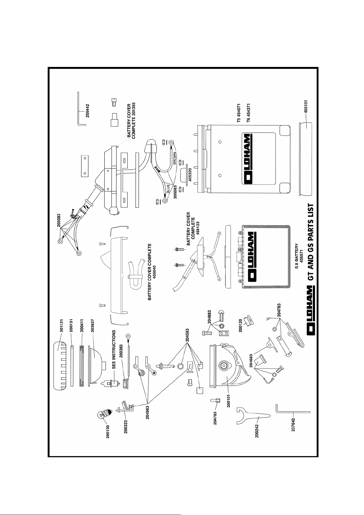
GT & GS DIAGRAM – ITEM LIST
200101. Headpiece shell
201121. Bezel ring
200131. Glass lens
200411. Sealing channel
203827. Reflector
200323. Small bulb socket
259130. Main bulb 4V 48 Lumen Halogen **
200130. Small bulb 4V 0.46A
200383. Prefocus reflector Bush and connection
203456. Cable 1.59m
455101. Plastic protection shoe
** dependant upon lamp type and temperature
classification
204983
HEADPIECE CONTACT KIT
Large bulb/switch connection
Small bulb/switch connection assembly
Switch connection
3/16” B HD screw
204583
SWITCH KNOB KIT
Switch knob
Switch knob sealing washer
Switch blade
Switch blade cowl
Grub Screw
204883
POSITIVE CHARGING SCREW KIT
Positive contact sealing washer
Charging contact screw
Large bulb socket block
Large bulb socket screw
205083
CABLE TERMINAL SPARES KIT
Cable grip
Sealing collar
Small terminal tag
Large terminal tag
Terminal sleeving Brown
Terminal sleeving Blue
Terminal tag (headpiece end)
204683
LOCK CONTACT KIT
Lock spring
Lock barrel
Lock contact
Lock contact screw
Lock contact sealing washer
204783
CAP CLIP KIT
Cap clip
Cap clip screw
Cap clip nut
Spring washer
Cap head lock pin
455045
PLASTIC BATTERY COVER COMPLETE
Clip for standard cover
Screw for plastic cover
Cable gland
Cable tie
614830
TOOL KIT
Small tools and spares kit for GT & GS lamps
comprising :-
Cable outlet gland key
Key for headpiece lock pin
Key for battery lock screw
Insulated screwdriver
Spring screwdriver
Key for battery terminal nuts
Topping up bottle (for T5 battery only)
Two main bulbs 4v / 0.75 amp Halogen
Two secondary bulbs 4v 0.46 amp
Two “T” battery fuses
Note: Only certain replacement items above may
be purchased individually. All others, as noted
above, must be purchased in kit form as this
ensures that other associated parts are also
available for replacement at the same time.

8
TROUBLESHOOTING
PROBLEM
CAUSE
1. Low battery capacity:
a. Observe the electrolyte level in the cell windows and
make certain level is between the two scribed lines on
the cell windows.
b. Continuous use of battery that has not been fully
charged will cause it to lose its capacity. This may be
corrected by cycling the battery several times
(discharge 8 hours and recharge 16 hours). Repeat
this procedure 3 times. If battery does not respond,
replace with a new one.
c. Battery not charged.
2. Loose connections:
a. Gently wiggle or pry each connection on top of the
battery to make sure it is tight and working properly.
b. Check the cables for broken conductors by twisting or
pulling it at various points along its length.
c. Check the headpiece terminals and the electrical
connections inside the headpiece in the same manner
as those on the battery.
d. Make sure the bulb is secure and making good
contact.
e. If the light flickers or dims when any of the preceding
items are being checked, that item should be repaired
or replaced.
Bulb glows dimly, flickers or fails
3. Electrolyte level:
a. Check at least once each month to see that the
electrolyte level is between the two scribed lines on
the cell window.
Battery not holding a charge during shift a. Make sure charger output is correct.
b. Check electrolyte level after charge
c. Make sure connections between headpiece and
battery are good.
d. Make sure that charging rack connections are good.
e. Make sure stored batteries are boost charged before
placing into service.
Battery capacity a. 13Ah battery recommended for 8-10 hour discharge /
16-14 hour charge, 5 days a week. Use the 16Ah
battery for greater cycle routines.
b. Check charger.
c. Check battery connections.
IMPORTANT : ALWAYS RECHARGE THE LAMP AFTER USE.
9
Certification, equipment marking and instructions for
compliance with ATEX standards:-
The GT and GS range of cap lamps are certified for use in Mines (Group I ) and Surface
(Group II ) areas where potentially explosive atmospheres may exist. The lamps are suitable for
M2 (Mining) and Group II 2 applications.
Certification codes are:-
Sira 02ATEX3175
Mining Group I:- EEx I ( Ta = -20oC to +40oC)
Surface Group II:- EEx II (Ta = 0oC to +40oC)
Warning the correct main bulb must be fitted to ensure the correct temperature classification.
Bulb Type Part Number Description Temperature Classification
B2 M259130 Prefocus Halogen Bulb 4.1v 48L T2
B2 M259530 Prefocus Halogen Bulb 4v 1.5A T2
B3 M259230 Prefocus Halogen Bulb 4v 0.75A T3
B4 M201230 Prefocus Krypton Bulb 4v 1A T4
Lamp Type Reference:-
The lamps can be assembled in a variety of combinations to satisfy customer requirements. The
assembly combination is stated on the certification label and this combination should not be
changed without consultation of Enersys Ltd., Swinton, Manchester UK.
The type code sequence is as below:-
1 2 3 4
Lamptop type Bulb type Battery Cover type Battery type
GStandard B2 S Stainless Steel T1 13Ah Low Maintenance
GH i.s. power Take off B3 LHand Lamp T2 16Ah Low Maintenance
B4 CCommunication Cover T3 13Ah Maintenance Free
PPlastic Cover T4 16Ah Maintenance Free
T5 16Ah Low Maintenance
T6 16Ah Maintenance Free
S8 8 Ah MF curved
S16 16Ah MF curved
1 2 3 4
Sample type code:- G B2 P T5

10
Use of equipment:-
The user must ensure that the lamp supplied meets the safety standard required for the Zoned
area:-
1. This equipment must only be used in a Category M2 or 2 / 3 zone. This equipment is not
suitable for a Category M1 or 1 zone.
2. Check the temperature classification and ensure the correct main bulb is fitted.
3. Check that the operating temperature range is in the range –20oC to +40oC for Mining and
0oC to +40oC for surface application.
4. The lamp must not be disassembled in a hazardous area.
5. The lamp must not be charged in a hazardous area.
6. The cap light and battery casings are manufactured from polycarbonate and ABS with
nitrile rubber seals. The performance of these materials, with respect to attack by
aggressive substances that may be present in the hazardous area, shall be taken into
account before the equipment is used.
7. Plastic surfaces may cause propagating brush discharges. Propagating brush discharges
are caused by non-conducting fluid flow over a non-conducting plastic surface. The cap
lights shall not be used in areas where a high fluid flow over the plastic surfaces may occur
(for example in the case of a ruptured process pipe or compressed air pipe).
EnerSys Ltd.,
Rake Lane,
Swinton
Manchester M27 8LR
UK
tel: +44 (0)161 727 3950 - 3955
September 2004
11
This manual suits for next models
1
Table of contents
Other EnerSys Lighting Equipment manuals

Popular Lighting Equipment manuals by other brands


Castaldi Lighting
Castaldi Lighting D51/0 thor Installation and maintenance sheet

KSIX
KSIX GLORY user manual

Generac Power Systems
Generac Power Systems MLTS owner's manual

EXTOL LIGHT
EXTOL LIGHT 43281 Translation of the original user manual

Procopi
Procopi AQUADECK EB Installation and maintenance instructions

Anslut
Anslut 005055 operating instructions