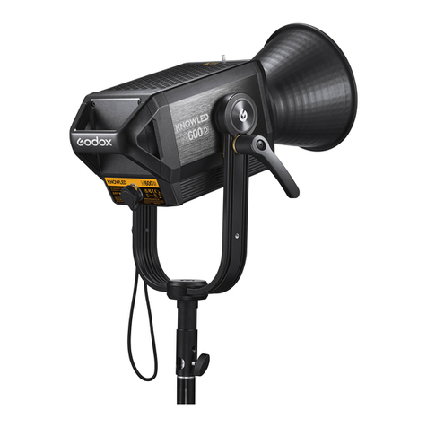
Godox MG2400Bi User manual

Important Safety Instructions and Precautions
Before use, please read and understand these instructions and attentions.
Professional lighting is prohibited for children. When children are near, parents or accompany-
ing persons must supervise closely to prevent children from personal injury due to collision
with lamps or private use of lamps.
This lighting product is not ordinary lighting product and cannot be used for general lighting.
Anyone who has suffered eye damage or has sensitive eyes should avoid using this product.
When the lamp is on, it must be used with care. Do not touch high-temperature parts, such as
LED lamp beads, to avoid burns.
When the lamp is on, it is forbidden to look directly at the lamp beads under any circumstances.
Strong light should be used under the guidance of professional lighting engineers. Avoid
prolonged exposure to strong light under any circumstances. If eye discomfort, please turn off
the lamp in time, suspend use, and see a doctor immediately.
If the lamp bead is damaged or deformed by heat, stop using this equipment, and contact the
manufacturer, service agent or qualified maintenance personnel to replace the lamp bead in
time to avoid accidents.
This product is only suitable for use in -20℃to 45℃operating environment and normal
humidity environment.
Do not use damaged equipment or accessories, and wait for professional maintenance
personnel to check and repair to confirm being normal before use.
During using, if the casing of this product is broken due to being dropped, squeezed or
subjected to strong impact, please do not use it, so as to avoid electric shock injury due to
contact with internal electronic components.
If an extension cord is required, please use an extension cord with a current rating greater than
or equal to that of the equipment. If an extension cord is rated less than the equipment,
overheating may result.
Some products have long power cords, please place the power cords properly and keep them in
a safe place. Avoid contacting the power cord with overheating surfaces, avoid improper
placement that could cause pulling damage, or trip on-site personnel. Please use the certified
power cord from the original manufacturer. If the product is damaged by using a non-certified
power cord, it will not be repaired by our factory.
Be sure to unplug equipment from the power outlet before cleaning and repairing. When not in
use, do not pull the power cord to unplug the equipment. For normal power-off, please hold
both ends of the plug of the equipment with your hands and pull the plug out of power outlet.
This equipment needs to be connected to a grounded outlet.
Do not disassemble the product without permission. If the product fails, it must be checked
and repaired by authorized maintenance personnel.
Before storing, make sure that the equipment has cooled down completely. For storage, unplug
the power cord from the equipment. The equipment should be placed in the carrying case or in
a ventilated dry place.
First of all, as the most basic principle: This product is a professional lighting set equipment
and should be used by professional lighting engineers or under the guidance of professionals.
Basic safety attentions must always be followed during use, as follows:
1.
2.
3.
4.
5.
6.
7.
8.
9.
10.
11.
12.
13.
14.

Forword
Thank you for purchasing!
MG2400Bi is a brand new high power LED light, with the following powerful features and functions:
input power of 2900W, support 100V-240V~50/60Hz power supply which allows you to use it
anywhere in the world, ultra-high and thousand-bit adjustable brightness, separate design of light
body and controller, IP54 rate, four dimming curves, wide CCT range from 2800K to 6500K, CRI≥96
& TLCI≥96, various wireless controlling methods, and etc. This new product is suitable for shooting
scenes in large-scale photography studios, film and television studios, broadcast studios, outdoor
exteriors and large field scenes.
Main Features
Warning
2600W strong output power in full CCT range.
Thousand-bit adjustable brightness from 0%to 100%.
Wide CCT range adjustable from 2800K to 6500K.
Super high CRI: CRI≥96,TLCI≥96
Four dimming curves: linear, S-curve, exponential, logarithmic.
Various wireless controlling methods: support DMX 512/LumenRadio CRMX/Bluetooth
App control.
With the brand new Godox G-Mount, communication contacts and intelligent accessory
recognition, the safety index for the use of high-power lighting fixture is significantly
improved.
IP54 rate keeps the light head and controller from dust and water.
Adopt efficient heat dissipation system design with large fan to meet the cooling needs of
large LED light.
11 FX modes: flash, lightning, cloudy, broken bulb, TV, candle, fire, firework, explosion,
welding, SOS.
Do not look directly at the LED light or illuminate at others’ eyes.
Do not plug or unplug the power cable or connecting cable when the power is turned on,
otherwise personal injuries may occur.
Do not cover the heat dissipation vent in working status.
Keep out of reach of children.
Please make sure to follow the instruction manual and correctly use this professional lighting
device.
keep these instructions! •
Do not place equipment near flammable and volatile solvents such as alcohol and gasoline.
Do not use accessories that are not recommended by our factory to avoid fire, electric shock
or personal injury.
When cleaning, do not wipe it with a damp cloth, please use a dry cloth or a soft cloth to wipe
the dirt of the equipment.
Please take off the protective cover before using.
This product complies with ROHS,CE,and FCC certification, please refer to the relevant
national standards for use and operation.
The safety instructions are formulated according to the strict testing of the factory, and the
design and specifications of the equipment are subject to change without prior notice. For
latest product information, please check the GODOX website and view latest electronic
instruction.
One-year warranty period, accessories such as consumable batteries, adapters, power cords,
etc. are not covered by this warranty.
If it is found that the equipment is repaired without authorization, the one-year warranty
period will be cancelled and relevant fees will be charged for maintenance.
Machine failures caused by non-standard operation are not covered by the warranty.
15.
16.
17.
18.
19.
20.
21.
22.
23.

1. Antenna Port
2. Remove Controller Port
3. DC Output Port
4. PRESET Button
5. LOCK Button
6. MENU Button
7. MODE Button
8. Adjust Dial
9. Wireless CRMX Indicator
10. Power Switch
11. Display
12. DMX OUT Port
13. DMX IN Port
14. AC Input Port
15. Ethernet Port
1. Handle 1
2. Handle 2
3. Direction Adjustment H andle
4. DC Input Port
5. Lanyard Attachment
6. Yoke
7. Mount Locking Pusher
8. Godox G-Mount
9. Quick Install Device
Name of Parts
Light Body
Controller
1
2
3
5
6
4
7
8
9
21 3
411
12
13
15
56 7 8 9 10
14

What’s Inside MG2400Bi What’s Inside MG2400Bi K1
Light Body × 1
Antenna × 1 Reflector × 1
Main Cable × 1 Tying Rope × 1 DMX Practical
Table × 1
Instruction
Manual × 1
DC Cable × 1
Pipe Clamp × 1 Light Protection
Cover × 1
Safety Wire × 1
Light Body Soft
Case SC18 × 1
Accessory Soft
Case SC19 × 1
Yoke × 1 Controller × 1 Light Body × 1
Antenna × 1 Reflector × 1
Main Cable × 1 Tying Rope × 1 DMX Practical
Table × 1
Instruction
Manual × 1
DC Cable × 1
Pipe Clamp × 1 Light Protection
Cover × 1
Safety Wire × 1
Yoke × 1 Controller × 1

What’s Inside MG2400Bi K2 Optional Accessories
Note: Due to continuous updates and
upgrades of the products, there may
be differences between the actual
products and the pictures. Therefore,
the pictures are for reference only,
products to prevail in kind.
Yoke G2400BY01
Fresnel Lens GF14
Parabolic
Softbox GP3
Parabolic
Softbox GP4
Parabolic
Softbox GP5
Reflector Kit GRK2
Octa GO3 Octa GO4 Octa GO5
Reflector Kit GRK
Light Body × 1
Antenna × 1 Reflector × 1
Main Cable × 1 Tying Rope × 1 DMX Practical
Table × 1
Instruction
Manual × 1
DC Cable × 1
Pipe Clamp × 1 Light Protection
Cover × 1
Safety Wire × 1
Yoke × 1 Controller × 1
Flight Case FC02 × 1

Installation and Disassembly
1. Installing the Yoke
1.1 Place the light on a flat surface with
the heat dissipation side upward.
1.3 Align both ends of the yoke with the
quick install device, lock the wrenches on
both sides, and then the "click" indicates
successful installation.
1.4 Install the light on the roller stand and
lock the fixing knob on the roller stand.
Please be careful when installing the light as it is
quite heavy.
Note: The roller stand is sold separately.
1.2 Press down the quick install device
button and remove the wrench.
Projection GP19K
Barndoor GR45B Barndoor GR30B
Soft Case SC18 Soft Case SC19
Projection GP26K Projection GP36K
Flight Case FC02

2. Disassembling the Yoke 4. Installing/Disassembling the Reflector
5. Installing the Controller on the Light Stand
6. AC Power Cord Connection Instructions
3. Installing/Disassembling the Light Protection Cover
2.1 Hold the handle of the light and
remove it from the roller stand then place
it on a flat surface.
4.1 Align the reflector with the mount,
insert and then rotate clockwise to install.
Wire 1 (yellow) is the ground wire, wire 2 (black) is
the neutral wire, while wire 3 (red) is the live wire.
Please ensure proper connection by matching the
corresponding wires to the appropriate terminals
on the plug before use.
4.2 Press and hold the mount locking
pusher and rotate counterclockwise to
remove the light protection cover.
5.1 Loosen the handle of pipe clamp and insert the light stand pole, rotate the handle clockwise to
lock the mounting device, then align the quick install device with the slot of mounting device and
insert it.
3.1 Align the light protection cover with
the mount and rotate clockwise to install.
3.2 Press and hold the mount locking
pusher and rotate counterclockwise to
remove the light protection cover.
2.2 Press and hold the quick install device
button and release the wrench to remove
the yoke.
Note: Make sure to align the reflector with the mount
of the lamp head.
①②③

7. Connect to DMX 512 Controller 8. Connect to Ethernet
Connection 1
Connection 2
DMX
Connection
DMX 512
DMX
Connection
Note: The DMX cable is sold separately.
Ethernet
Ethernet
DMX512
CRMX TX
7.1 Wireless DMX Connection
7.2 Wired DMX Connection
CRMX
CRMX
CRMX
CRMX
CRMX
CRMX
DMX
Connection DMX
Connection DMX
Connection DMX
Connection
CRMX

Power Supply
Power On/Off
8 Firework
Connect the device to the power source
and briefly press the power switch button
on the controller to turn it on or off.
In the brightness setting interface, turn the adjust
dial to adjust the brightness ratio from 0% to
100%.
Turning the adjust dial clockwise once will
increase the value by 0.1 unit, while turning it
counterclockwise once will decrease the value by
0.1 unit. Quick adjustment is also available during
rapid rotation.
CCT Mode
FX Mode
1. Flash Effect
Briefly press the MODE button to switch to CCT mode. Briefly press the adjust dial to switch
between the brightness setting interface and color temperature setting interface.
Note: Do not plug or unplug the power cord or connecting cable when the power is turned on, otherwise injuries may occur.
85.2%2800 K
In the color temperature setting interface, turn the adjust dial to adjust the color temperature
from 2800K to 6500K.
Turning the adjust dial clockwise once will increase the value by 100 units, while turning it
counterclockwise once will decrease the value by 100 units.
Briefly press the MODE button to switch to FX
mode. Turn the adjust dial to switch among the
following 11 effects: flash, lightning, cloudy,
broken bulb, TV, candle, fire, firework, explosion,
welding, SOS.
Select the desired lighting effect and briefly
press he adjust dial to enter the effect setting
interface.
In the flash effect setting interface, turn the
adjust dial to select options among switch, dim,
CCT, auto, manual, speed, mode, etc. Briefly
press the adjust dial to select the desired option
then turn the dial to adjust the options (except
for the auto and manual options). Finally,
continuously press the adjust dial/briefly press
the MODE button to return to the previous menu.
Note: If manual is selected, the flash effect can
be triggered once by briefly pressing the adjust
dial.
Switch: Turn on/off the effect
Dim: 0%-10 0%
CCT: 2800K-6500K
Speed: 1-100
Mode: Camera Flash/Flash Bulb
2. Lightning Effect
In the lightning effect setting interface, turn the
adjust dial to select options among switch, dim,
CCT, auto, manual, times, frequency, etc. Briefly
press the adjust dial to select the desired option
then turn the dial to adjust the options (except
for the auto and manual options). Finally,
continuously press the adjust dial/briefly press
the MODE button to return to the previous menu.
Note: If manual is selected, the lightning effect
can be triggered once by briefly pressing the
adjust dial.
Switch: Turn on/off the effect
Dim: 0%-10 0%
CCT: 2800K-6500K
Times: Random/1-10
Frequency: Random /2-20
AC100V-240V

Note: If manual is selected, the explosion effect
can be triggered once by briefly pressing the
adjust dial.
3. Cloudy Effect
In the cloudy effect setting interface, turn the
adjust dial to select options among switch, dim,
ratio, speed, etc. Briefly press the adjust dial to
select the desired option then turn the dial to
adjust the options. Finally, continuously press
the adjust dial/briefly press the MODE button to
return to the previous menu.
Switch: Turn on/off the effect
Dim: 0%-10 0%
Ratio:10%-90%
Speed: Random/1-100
7. Fire Effect
In the fire effect setting interface, turn the adjust
dial to select options among switch, dim, speed,
etc. Briefly press the adjust dial to select the
desired option then turn the dial to adjust the
options. Finally, continuously press the adjust
dial/briefly press the MODE button to return to
the previous menu.
Switch: Turn on/off the effect
Dim: 0%-10 0%
Speed: 1-100
4. Broken Bulb Effect
In the broken bulb effect setting interface, turn
the adjust dial to select options among switch,
dim, CCT, speed, etc. Briefly press the adjust dial
to select the desired option then turn the dial to
adjust the options. Finally, continuously press
the adjust dial/briefly press the MODE button to
return to the previous menu.
Switch: Turn on/off the effect
Dim: 0%-10 0%
CCT:2800K-6500K
Speed: 1-100
5. TV Effect
In the TV effect setting interface, turn the adjust
dial to select options among switch, dim, speed,
etc. Briefly press the adjust dial to select the
desired option then turn the dial to adjust the
options. Finally, continuously press the adjust
dial/briefly press the MODE button to return to
the previous menu.
Switch: Turn on/off the effect
Dim: 0%-10 0%
Speed: 1-100
6. Candle Effect
In the candle effect setting interface, turn the
adjust dial to select options among switch, dim,
speed, etc. Briefly press the dial to select the
desired option then turn the adjust dial to adjust
the options. Finally, continuously press the
adjust dial/briefly press the MODE button to
return to the previous menu.
Switch: Turn on/off the effect
Dim: 0%-10 0%
Speed: 1-100
8. Firework Effect
In the firework effect setting interface, turn the
adjust dial to select options among switch, dim,
speed, embers, etc. Briefly press the adjust dial
to select the desired option then turn the dial to
adjust the options. Finally, continuously press
the adjust dial/briefly press the MODE button to
return to the previous menu.
Switch: Turn on/off the effect
Dim: 0%-10 0%
Speed: 1-100
Embers: 01-100
9. Explosion Effect
In the explosion effect setting interface, turn the
adjust dial to select options among switch, dim,
CCT, auto, manual, speed, embers, etc. Briefly
press the adjust dial to select the desired option
then turn the dial to adjust the options (except
for the auto and manual options). Finally,
continuously press the adjust dial/briefly press
the MODE button to return to the previous menu.
Switch: Turn on/off the effect
Dim: 0%-10 0%
CCT: 2800K-6500K
Speed: 1-100
Embers: 1-100
10. Welding Effect
In the welding effect setting interface, turn the
adjust dial to select options among switch, dim,
CCT, speed, etc. Briefly press the adjust dial to
select the desired option then turn the dial to
adjust the options. Finally, continuously press
the adjust dial/briefly press the MODE button to
return to the previous menu.
Switch: Turn on/off the effect
Dim: 0%-10 0%
CCT: 2800K-6500K
Speed: 1-100

Menu Settings
Note: The default dimming curve in FX mode is
linear.
11. SOS Effect
1. DMX
In the SOS effect setting interface, turn the
adjust dial to select options among switch, dim,
CCT, etc. Briefly press the adjust dial to select
the desired option then turn the dial to adjust the
options. Finally, continuously press the adjust
dial/briefly press the MODE button to return to
the previous menu.
Briefly press the adjust dial to enter DMX setting interface. Turn the adjust dial to select options
among address, DMX mode, RDM state, DMX lost, termination, extend DMX channels. Briefly
press the adjust dial to select the desired option then turn it to adjust settings. Finally, briefly
press the adjust dial to exit the current setting, briefly press the MENU button to return to the
previous menu.
Interface when connected to DMX
Briefly press the MENU button to enter menu
settings, turn the adjust dial to select among the
following options: DMX, CRMX, Bluetooth,
Network settings, Art-Net & sACN, optics
recognition, power limit,dimming curves,fan,
display, language, version & upgrade, factory
reset, fixture info.
Switch: Turn on/off the effect
Dim: 0%-10 0%
CCT: 2800K-6500K
1
DHCP
ON
English
V0.13
MG2400Bi
DMX
Interface when connected to CRMX
CRMX
Level 1 Option
Address
DMX Mode
RDM State
DMX Lost
Termination
Extend DMX
Channels
Level 2 Option
1-512
01:CCT 8 bit
02:FX 8 bit
03:CCT 16 bit
04:FX 16 bit
05:ULTIMATE DMX 8 bit
06:ULTIMATE DMX 16 bit
On
O
Hold Last Command
Black Out
Black Out After 2 Min
On
O
On
O
Description
Initial address
CCT Mode in 8 bit
FX Mode in 8 bit
CCT Mode in 16 bit
FX Mode in 16 bit
DMX Mode in 8 bit
DMX Mode in 16 bit
Turn on RDM
Turn o RDM
After the DMX control signal is lost, continue to use the last received
DMX control signal until power down or a valid DMX control signal is
received again.
The light is o immediately.
After the DMX control signal is lost, continue to use the last received
DMX control signal for 2 minutes then black out.
Note: If a valid DMX control signal is received within 2 minutes, then
use the new DMX control signal.
Turn on DMX terminal
Turn o DMX terminal
Turn on extend DMX channels
Turn o extend DMX channels
DMX Mode 01:CCT 8 Bit
On
Black Out After 2 Min
RDM State
DMX Lost
ULTIMATE DMX 16BIT ULTIMATE DMX 16BIT
O O

Note: Please refer to the DMX Practical Table to control the device by DMX/RDM. The electronic version can be
downloaded from the official website https://www.godox.com.
Note: Before selecting the transmit mode/receive mode, perform a reset first.
Note: The app can be used directly on the firstly installed
device (smartphone or iPad). When change to other mobile
device (smartphone or iPad), the light shall be reset before the
normal connection of the app.
2. CRMX
Briefly press the adjust dial to enter CRMX setting interface. Turn the adjust dial to select options
between switch and mode. Briefly press the adjust dial to select the desired option then turn it to
adjust settings. Finally, briefly press the adjust dial to exit the current setting, briefly press the
MENU button to return to the previous menu.
3. Bluetooth
Briefly press the adjust dial to enter Bluetooth setting interface. Turn the adjust dial to select
options between switch and reset. Briefly press the adjust dial to select the desired option then
turn the dial to adjust settings. Finally, briefly press the MENU button to return to the previous
menu.
4. Network Settings
Briefly press the adjust dial to enter network
settings interface. Turn and briefly press the
adjust dial to select network mode, then turn the
dial to select among DHCP, Art-Net 2.x, Art-Net
10.x and manual. Finally, briefly press the MENU
button to return to the previous menu.
Scan the QR code to download the "Godox
Light" smartphone app version 3.0 or above
(can be used in Android and iOS).
Transmitter mode in CRMX Receiver mode in CRMX
Level 1 Option
CRMX
Mode
Output Power
Status
Level 2 Option
On
Off
Transmitter
Receiver
5dBm
11dBm
16dBm
20dBm
Link
Linking
Description
Turn on CRMX
Turn off CRMX
Transmitter mode
Receiver mode
Output power value = 5dBm (only adjustable in transmitter mode)
Output power value = 11dBm (only adjustable in transmitter mode)
Output power value = 16dBm (only adjustable in transmitter mode)
Output power value = 20dBm (only adjustable in transmitter mode)
To enter linked status (only adjustable in transmitter mode)
Linking (only adjustable in transmitter mode)
MODE MODE
Reset Reset
Reset
CRMX
02�00�00�00�00�00
DHCP
Status
Godox KNOWLED App

Note: The light will not be lightened if the optics is not correctly
installed even optics recognition function is turned on.
Note: If the power supply environment is unable to meet the
requirements for powering on, you can activate this function
while the device is in the powered-off state. Simultaneously
press the Preset button and MODE button, and the device will
automatically enter the Power Limit mode upon startup
(default power limitation is set to 50%).
5. Art-Net & sACN
Briefly press the adjust dial to enter Art-Net &
sACN setting interface. Turn and briefly press the
adjust dial to select options among auto, Art-Net,
sACN and off, then other level 2 options are
available to adjust. Finally, briefly press the
MENU button to return to the previous menu.
6. Optics Recognition
Briefly press the adjust dial to enter optics
recognition setting interface. Turn and briefly
press the adjust dial to turn the function on or
off. Finally, briefly press the MENU button to
return to the previous menu.
7. Power Limit
Briefly press the adjust dial to enter power limit
setting interface. Rotate and briefly press the
adjust dial to turn the function on or off. Finally,
briefly press the MENU button to return to the
previous menu.
Max. limit:10%-100%
Level 1 Option
Network Mode
IP
Subnet Mask
Default
Gateway
Level 2 Option
DHCP
Art-Net 2.x
Art-Net 10.x
Manual
AAA.BBB.CCC.DDD
255.BBB.CCC.DDD
AAA.BBB.CCC.DDD
Description
DHCP mode
To use 2.B.C.D network
To use 10.B.C.D network
Set the network IP, subnet mask, and default gateway manually.
The ID address is assigned by DHCP in DHCP mode.
The ID address is 2.B.C.D in Art-Net 2.x mode.
The ID address is 10.B.C.D in Art-Net 10.x mode.
In manual mode:
AAA=0-255
BBB=0-255
CCC=0-255
DDD=0-255
The subnet mask is 255.BBB.CCC.DDD and can not be adjusted by
menu settings in DHCP/Art-Net 2.x/Art-Net 10.x mode.
In manual mode:
AAA=0-255
BBB=0-255
CCC=0-255
DDD=0-255
The default gateway is assigned by DHCP in DHCP mode.
The default gateway is 2.B.C.D in Art-Net 2.x mode.
The default gateway is 10.B.C.D in Art-Net 10.x mode.
In manual mode:
AAA=0-255
BBB=0-255
CCC=0-255
DDD=0-255
Level 1 Option
Art-Net&sACN
Art-Net Net
Art-Net Sub-Net
Art-Net Port
Art-Net Universe
sACN Universe
Level 2 Option
Auto/Ar t-Net/sACN/Off
0-127
0-15
0-15
0...32767
1...63999
Description
Auto:Art-Net & sACN two protocols are accepted.
Art-Net:Only Art-Net protocol.
sACN:Only sACN protocol.
Off:No network protocols are accepted.
Art-Net network
Choose Art-Net subnet in Art-Net network.
Art-Net port
Art-Net universe
sACN universe

8. Dimming Curves
Briefly press the adjust dial to enter dimming
curves setting interface. Rotate and briefly press
the adjust dial to choose among linear, S-curve,
exponential and logarithmic. Finally, briefly press
the adjust dial/MENU button to return to the
previous menu.
11. Language
Briefly press the adjust dial to enter language
setting interface. Rotate and briefly press the
adjust dial to select between Simplified Chinese
and English. Finally, briefly press the MENU
button to return to the previous menu.
12. Version & Upgrade
Briefly press the adjust dial to enter version &
upgrade setting interface to check the firmware
version of lamp head & controller and upgrade
instruction. Then, short press the MENU button
to return to the previous menu.
13. Factory Reset
To access the factory reset interface, briefly
press the adjust dial. Rotate the adjust dial to
select "Yes" or "No," then briefly press the adjust
dial to complete the setting. Once you have
confirmed the factory reset, the light fixture will
restart, and the interface will automatically
display options for Chinese and English. Rotate
the dial to select an option and then press the
dial to confirm the setting. At this point, the
brightness value of the light will automatically be
set to 100% and the interface will return to CCT
mode interface.
9. Fan
Briefly press the adjust dial to enter fan setting
interface. Rotate and briefly press the adjust dial
to choose among mute, auto, medium, and high.
Finally, briefly press the adjust dial/MENU button
to return to the previous menu.
10. Display
Briefly press the adjust dial to enter display
setting interface. Rotate and briefly press the
adjust dial to adjust display brightness from 10%
to 100%. Finally, briefly press the MENU button to
return to the previous menu.
FAN
OFF
Auto Medium High
Language
Version&Upgrade
Inse The U Disk With New
Firmware After Power O,
Then Reboot To Upgrade The
Device.
Box:V0.13 Lamp:V0.03

14. Fixture Info
Briefly press the adjust dial to enter fixture info setting interface to check model, UID NO., firmware
version of lamp head and controller, light head temp., lamp maintenance time reminder,
certification etc. Then, briefly press the MENU button to return to the previous menu.
When the lamp head displays a remaining
maintenance time of 0 hours, it is recommended for
the customer to clean the glass or other parts of the
lamp head. We suggest using a dry or soft cloth to
wipe away any dirt or debris on the equipment. Once
the maintenance is complete, if you choose to reset,
the lamp head maintenance time will start counting
again.
Briefly press the LOCK button, the panel is locked
when < > is displayed on the panel, briefly
press again to unlock.
Note: The locking function only works on the controller
panel, other operations are still available.
Notes:
1. New firmware must be downloaded from the official website, and keep only one BIN file in the root directory of the
USB disk.
2. The USB Type-A port can only support output voltage and current of 5V/1.5A. Do not connect to over-rated USB
device.
Note: If light effect data has been previously saved, there
will be an additional option.
MG2400Bi
Box:V0.12 Lamp:V0.01
1000
Lock Setting
Briefly press the PRESET button to enter preset
effects interface. Rotate and briefly press the
adjust dial to choose and enter preset effects
1-20, then briefly press to select save or cancel.
Then, briefly press the adjust dial to return to the
previous menu and briefly press the PRESET
button to exit.
This product, except consumables, is supported with a one-year warranty.
Unauthorized service will void the warranty.
Maintenance of the light must be performed by our authorized maintenance department which
can provide original accessories.
If the product had failures or become wet, do not use it until it is repaired by professionals.
Shut down the device immediately should abnormal operation be detected.
Cancel: Return to the previous interface.
Apply: Apply this set of preset lighting effects.
Save: Save the current lighting effect of the light
fixture.
Preset Setting
Maintenance
Insert The U Disk With New Firmware After Power Off, Then Reboot To Upgrade The Device.
Box:0.13 Lamp:V0.03
Version&Upgrade
1.1 Download the new firmware to the U disk from official website (https://www.godox.com.cn/-
firmware-continuous-light).
1.2 Turn off the device. Insert the U disk with new firmware into the USB Type-A port.
1.3 Turn on the device, and MG2400Bi controller will automatically enter the upgrading interface.
1.4 It will return to main interface after completion.
Software Upgrade
1.Firmware version of controller
2.1 Download the new firmware to the U disk from official website (https://www.godox.com.cn/-
firmware-continuous-light).
2.2 Turn off the device. Insert the U disk with new firmware into the USB Type-C port.
2.3 Turn on the device, and MG2400Bi lamp head will automatically enter the upgrading interface.
2.4 It will return to main interface after completion.
2.Firmware version of lamp head
8 Firework
1
2
3
Save
Cancel
Apply

The above data is not absolute values but rather average values. All tests were conducted with the light at 100% brightness.
Specifications and data may subject to changes without notice.
Photometric Data Technical Data
Model
Power Supply
Max. Power
CCT
Brightness Range
Dimming Curves
FX Modes
CRI
TLCI
Waterproof Grade of Light
Body/Controller
Controlling Methods
Bluetooth Controlling Distance
USB Type-A Port
Dimension(Yoke and reflector
are not included in the light
body)
Netweight≈
MG2400Bi
100V-240V~50/60Hz 30A(Max.)
≈2900W
2800-6500K
0%-100%
linear, S-curve, exponential, logarithmic
11
Average≥96
Average≥96
IP54
DMX 512 Control(support RDM protocol/LumenRadioCRMX)/RC-A6 Remote
Control/Bluetooth App Control /Ethernet (support Art-Net & sACN
protocol)/Remove Controller/Light Body Control(Remove Controller RC11 is
sold separately)
Max. 100m
Firmware Upgrade/5V 1.5A Power Supply
Light Body:16.10 ” ×15.16”×14.02”
Controller:11.02‘*16.54“*8.27”
Light Body(Yoke and reflector not included):20kg
Controller:13kg
3m
≈8810
≈818
≈9700
≈901
≈11600
≈1080
≈12000
≈1120
≈11300
≈1050
5m
≈3540
≈329
≈3950
≈367
≈4740
≈440
≈4890
≈454
≈4650
≈432
7m
≈2120
≈197
≈2360
≈220
≈2840
≈264
≈2900
≈269
≈2730
≈254
9m
≈1480
≈137
≈1640
≈152
≈1920
≈179
≈1970
≈183
≈1870
≈174
10m
≈1250
≈116
≈1380
≈128
≈1650
≈153
≈1700
≈158
≈1600
≈149
lux
fc
lux
fc
lux
fc
lux
fc
lux
fc
Bare Light
Testing
Condition
3m
≈32200
≈2990
≈35900
≈3340
≈43200
≈4020
≈44600
≈4140
≈42100
≈3910
5m
≈11700
≈1090
≈13000
≈1200
≈15700
≈1460
≈16200
≈1500
≈15300
≈1420
7m
≈6240
≈580
≈6900
≈641
≈8340
≈775
≈8590
≈798
≈8110
≈753
9m
≈4000
≈372
≈4450
≈413
≈5370
≈499
≈5520
≈513
≈5260
≈489
10m
≈3380
≈314
≈3740
≈348
≈4490
≈417
≈4650
≈432
≈4400
≈408
lux
fc
lux
fc
lux
fc
lux
fc
lux
fc
With
Reector
(45°)
CCT
2800K
3200K
4300K
5600K
6500K
CCT
2800K
3200K
4300K
5600K
6500K
Illuminance
Unit
Illuminance
Unit
Testing
Condition

This device complies with part 15 of the FCC Rules. Operation is subject to the following two
conditions:
(1) This device may not cause harmful interference, and
(2) this device must accept any interference received, including interference that may cause
undesired operation.
Any Changes or modifications not expressly approved by the party responsible for compliance
could void the user's authority to operate the equipment.
Note: This equipment has been tested and found to comply with the limits for a Class B digital
device, pursuant to part 15 of the FCC Rules. These limits are designed to provide reasonable
protection against harmful interference in a residential installation. This equipment generates uses
and can radiate radio frequency energy and, if not installed and used in accordance with the
instructions, may cause harmful interference to radio communications. However, there is no
guarantee that interference will not occur in a particular installation. If this equipment does cause
harmful interference to radio or television reception, which can be determined by turning the
equipment off and on, the user is encouraged to try to correct the interference by one or more of
the following measures:
-Reorient or relocate the receiving antenna.
-Increase the separation between the equipment and receiver.
-Connect the equipment into an outlet on a circuit different from that to which the receiver is
connected.
-Consult the dealer or an experienced radio/TV technician for help.
The device has been evaluated to meet general RF exposure requirement.
The device can be used in portable exposure condition without restriction.
Operatingfrequency: 2402MHz–2480MHz(BT)
MaximumEIRPPower:5dBm
FCC Statement
Warning
GODOX Photo Equipment Co.,Ltd. hereby declares that this equipment are in compliance with the
essential requirements and other relevant provisions of Directive 2014/53/EU. In accordance with
Article 10(2) and Article 10(10), this product is allowed to be used in all EU member states.For more
information of DoC, Please click this web link:
https://www.godox.com/eu-declaration-of-conformity/
The device complies with RF specifications when the device used at 0mm from your body.
Declaration of Conformity
Warranty
Dear customers, as this warranty card is an important certificate to apply for our maintenance service,
please fill in the following form in coordination with the seller and safe-keep it. Thank you!
Product
Information
Customer
Information
Seller
Information
Note
Model
Name
Address
Name
Contact Number
Address
Date of Sale
Product Code Number
Contact Number
Note: This form shall be sealed by the seller.
The document applies to the products listed on the Product Maintenance lnformation (see below for further
information). Other products or accessories (e.g. promotional items,giveaways and additional accessories
attached,etc.) are not included in this warranty scope.
Applicable Products
Warranty Period
The warranty period of products and accessories isimplemented according to the relevant Product
Maintenance Information. The warranty period is calculated from the day(purchase date) when the product
is bought for the first time,And the purchase date is considered as the date registered onthe warranty card
when buying the product.
How to Get the Maintenance Service
If maintenance service is needed, you can directly contact the product distributor or authorized service
institutions. You can also contact the Godox after-sale service call and we will offer you service. When
applying for maintenance service, you should provide valid warranty card. If you cannot provide valid
warranty card, we may offer you maintenance service once confirmed that the product or accessory is
involved in the maintenance scope, but that shall not be considered as our obligation.
Inapplicable Cases
The guarantee and service offered by this document are not applicable in the following cases: ①The
product or accessory has expired its warranty period; ②Breakage or damage caused by inappropriate
usage, maintenance or preservation, such as improper packing, improper usage, improper plugging
in/out external equipment, falling off or squeezing by external force, contacting or exposing to the
improper temperature, solvent, acid, base, flooding and damp environments, etc; ③Breakage or
damage caused by non-authorized institution or staff in the process of installation, maintenance,
alternation, addition and detachment; ④The original identifying information of product or accessory is
modified, alternated, or removed; ⑤No valid warranty card; ⑥Breakage or damage caused by using

The warranty period and service types of products are implemented according to the following Product
Maintenance Information:
Maintenance and Service Support Information
12
12
No
3
Circuit Board Customer sends the
product to
designated site
Customer sends the
product to
designated site
Customer sends the
product to
designated site
Battery
Electrical parts e.g.battery
charger, etc.
Without warranty
Parts
Other
Items
Power cord, lamp cover,lockingdevice,
package, etc.
Product
Type Name Maintenance
Period(month) Warranty
Service Type
illegally authorized, nonstandard or non-public released software; ⑦Breakage or damage caused by
force majeure or accident; ⑧Breakage or damage that could not be attributed to the product itself. Once
met these situations above, you should seek solutions from the related responsible parties and Godox
assumes no responsibility. The damage caused by parts, accessories and software that beyond the
warranty period or scope is not included in our maintenance scope. The normal discoloration, abrasion and
consumption are not the breakage within the maintenance scope.
This manual suits for next models
1
Other Godox Lighting Equipment manuals

Godox
Godox SL Series User manual

Godox
Godox Knowled MG1200BI User manual

Godox
Godox ML-150 II User manual

Godox
Godox WITSTRO+ AR400 User manual

Godox
Godox ML60Bi User manual

Godox
Godox SZ200 Bi User manual

Godox
Godox LR180 User manual

Godox
Godox LED1000D II User manual

Godox
Godox LED 36 User manual

Godox
Godox AD300Pro User manual
Popular Lighting Equipment manuals by other brands

Star Phantom
Star Phantom ULB42-1 Instructions for intallation

LSC
LSC Smart Connect 3008407 Getting started

Viking
Viking WARRIOR VK132-2R instruction manual

American DJ
American DJ Mega Par Profile System User instructions

Saxby Lighting
Saxby Lighting EL-20079 Instruction leaflet

Showlite
Showlite LTS-100 manual