MI/1749 - 5aed. DEU - 11/2017 D51/0 thor - D51/0 CM
1
Das Produkt entspricht den Richtlinien
der Europäischen Gemeinschaft
Montageanleitung - Instandhaltung
WICHTIGER HINWEIS: diese Montageanleitung informiert den Anwender über die korrekten Wartungsmaßnahmen und den Austausch der Lampen. Jede Manipulation und/
oder Veränderung des Geräts, das in dem gelieferten Zustand installiert und verwendet werden muss und den nationalen Normen für Anlagen entspricht, ist verboten.
Bei unsachgemäßer Installation verfallen jegliche Garantieansprüche und die Firma haftet nicht für Schäden aufgrund einer unsachgemäßen Installation. DIE INSTALLATION
MUSS VON QUALIFIZIERTEM FACHPERSONAL DURCHGEFÜHRT WERDEN.
Qualitätskontrolle: Sollten Sie Reklamationen haben, wenden Sie sich an unsere Firma oder an unsere Verkaufsorganisation unter Angabe des Bestelldatums
und der Kennummer des Geräts
. / Technische Anderungen vorbehalten!
LED-VERSION:
Die Lichtquelle dieses Geräts darf nur vom Hersteller, seinem Kundendienst oder entsprechend qualifiziertem Personal ausgetauscht werden.
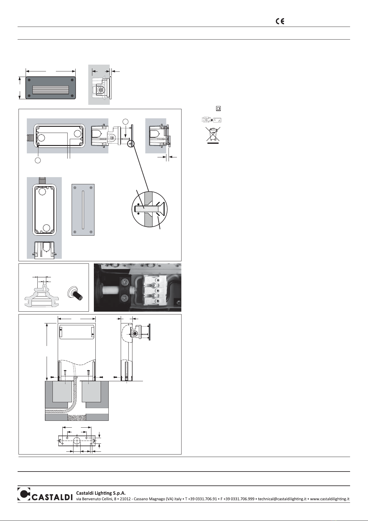
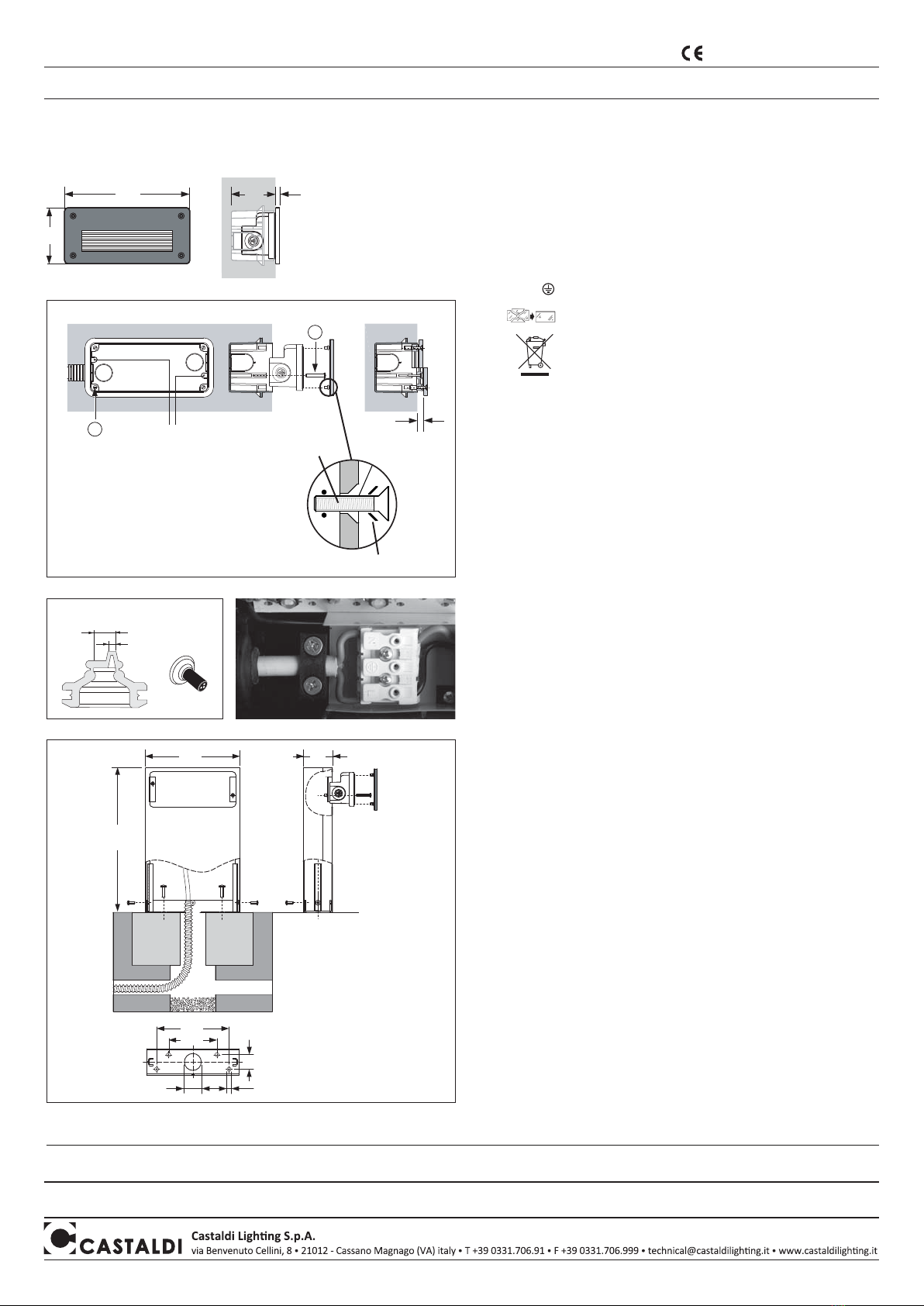
A
B9
Befestigung Lochen
85
190 65 GLAS Version: 7 mm
METALL Version: 12 mm
Abb. 1
196 60
30
100
Ø8,5Ø35
300
150
Abb. 4
Ø 7,5 ÷ 13mm
Ø 2,5 ÷ 4mm
Abb. 2
Abb. 3
KUNSTSTOFFSCHEIBE
OR Dichtung
version D51/0-LW
version D51/0-LWLT-MAL • Die Schalung in die Gussbewehrung mit dem oberen Rand bündig
zur fertigen Mauer einsetzen. (Abb.1)
• Das Schutzrohr des Stromkabels in den Guss einsetzen.
• Nach erfolgtem Guss wie folgt für die Montage vorgehen:
Zum Öffnen der Leuchte die 4 Schrauben der Glasscheibe lösen, den
Reflektor (2 Schrauben) herausnehmen und das Speisekabel durch die
Membrane. (Abb.2)
• Bei der Installation die anlagentechnischen Vorschriften streng befolgen.
• Für Montagen im Freien ist (CEI EN 60598-1; EN 50525) ein biegsames
Neopren Gummikabel Typ H07RN-F mit Durchmesser zwischen
7,5 und 12 mm vorgeschrieben.
Nicht zulässig sind PVC-isolierte Kabel oder mit PVC-Mantel oder auf jeden
Fall andere als die hier angegebenen. Für die korrekte Verbindung
Kabel-Membrane wie in Abb. 2 veranschaulicht vorgehen.
• Das Kabel muss unterhalb der entsprechenden Brücke verlaufen und 3 mm ~
hinausstrecken (Abb. 3).
• Die Leuchte an der Schalung mit den zwei Schrauben “A” befestigen;
eventuelles Hervorstehen der Leuchte kann durch Festschrauben
der 4 Stifte “B” korrigiert werden (Abb.1).
• Die Leuchte unter Beachtung der Polung anschliessen, die Kabelschelle
festziehen. Den Reflektor wieder aufsetzen, nachprüfen, dass die Dichtung
festsitzt und die Glasscheibe und Rahmen durch Festziehen der Schrauben
wieder anmontieren; für eine korrekte Festspannung müssen diese
gleichmässig und stufenweise zugeschraubt werden.
• Die befestigung der Säule auf einer geeigneten Stütze vornehmen (gestampfter
Zement oder dergleichen) und dabei vermeiden, daß sich umdie Grundplatte
herum Wasserpfützen bilden.
• Die Leuchte an der Säule wie in Abb. 4 angegeben mit den mitgelieferten
Bestandteilen befestigen.
ZU BEACHTEN:
• Für die Befestigung der Basis 4 Dübel verwenden.
• Die Säule wird mit einer Kunststoffschutzfolie geliefert, die nach der Installation
entfernt werden muss.
Lampenaustausch - Wartungs:
• Vor jeglichem Wartungseingriff die Spannung abschalten.
Zum Austausch der Led-Lampe, wenden Sie sich an unsere Firma oder
an unsere Verkaufsorganisation. Bevor Sie das Gerät offnen, müssen Sie
gründlich reinigen. Verformte oder nicht in einwandfreiem Zustand
befindliche Dichtungen müssen ausgetauscht werden.
• Die Glasscheibe und die äussere Oberfläche der Leuchte müssen
unbedingt periodisch gereinigt werden, damit sich keine Erd- oder
Schmutzablagerungen bilden. Solche Ablagerungen können gefährliches
Überhitzen verursachen und dadurch korrekte Lichtaussendung und korrekte
Wärmedissipation verhindern. Eventuelle Kalkverkrustungen am Glas müssen
mit einem Schaber entfernt werden.
Installation D51/0-CM:
Installation D51/0 - Leuchte:
Eigenschaften - Bedeutung der Symbole auf dem Typenschild
:
Die Leuchte ist für den Innen - sowie den Aussenbereich geeignet
Montage: Wandeinbau oder auf einer Säule
IP65
Klasse II Doppelisolierung
Schutzleiteranschluss nicht zulässig
die beschädigten Schutzgläser ersetzen
Das Entsorgen im Hausmüll ist verboten!
Bei Ablauf der Lebensdauer bitte beachten:
Abfalltrennung ist Pflicht
Absolut staubdicht
Schutz gegen Wasserstrahlen aus allen Richtungen