Enfinity 1000TL User manual

Enfinity
PVinverter
Installation guide
www.enfinity.biz
EN
1000TL / 1650TL / 2200TL / 2800TL / 3300TL / 3680TL / 4400TL / 5000TL

2
Copyright declaration
Copyright of this manual belongs to Enfinity.
No corporation or individual should plagiarize,
partially or fully copy, reproduce or distribute this
document (including software, etc.) in any form
or by any means without the express permission
of Enfinity. All rights reserved. Enfinity reserves
the right of final interpretation. This information is
subject to change without notice. Version – 003, August 2011

3
Contents
1 Notes on this manual������������������������������������������������������������������������������������������������������������������������������������������������������������4
1.1 Validity ���������������������������������������������������������������������������������������������������������������������������������������������������������������������������������������������������� 4
1.2 Target group ���������������������������������������������������������������������������������������������������������������������������������������������������������������������������������������� 4
1.3 Symbols used �������������������������������������������������������������������������������������������������������������������������������������������������������������������������������������� 4
2 Safety���������������������������������������������������������������������������������������������������������������������������������������������������������������������������������������������������5
2.1 Appropriate usage�����������������������������������������������������������������������������������������������������������������������������������������������������������������������������5
2.2 Important safety instructions�������������������������������������������������������������������������������������������������������������������������������������������������������5
2.3 Explanation of symbols�������������������������������������������������������������������������������������������������������������������������������������������������������������������6
3 Introduction����������������������������������������������������������������������������������������������������������������������������������������������������������������������������������� 8
3.1 Basic features���������������������������������������������������������������������������������������������������������������������������������������������������������������������������������������8
3.2 Electrical block diagram �����������������������������������������������������������������������������������������������������������������������������������������������������������������8
3.3 Dimension and weight���������������������������������������������������������������������������������������������������������������������������������������������������������������������9
4 Technical data��������������������������������������������������������������������������������������������������������������������������������������������������������������������������� 10
4.1 Input (DC) ��������������������������������������������������������������������������������������������������������������������������������������������������������������������������������������������10
4.2 Output (AC) ����������������������������������������������������������������������������������������������������������������������������������������������������������������������������������������10
4.3 Eciency, safety and protection����������������������������������������������������������������������������������������������������������������������������������������������� 11
4.4 General data����������������������������������������������������������������������������������������������������������������������������������������������������������������������������������������� 11
5 Function�������������������������������������������������������������������������������������������������������������������������������������������������������������������������������������������12
6 Installation�������������������������������������������������������������������������������������������������������������������������������������������������������������������������������������13
6.1 Packaging��������������������������������������������������������������������������������������������������������������������������������������������������������������������������������������������� 13
6.2 Identification of the Enfinity inverter �������������������������������������������������������������������������������������������������������������������������������������14
6.3 Installation precautions�����������������������������������������������������������������������������������������������������������������������������������������������������������������14
6.4 Position�������������������������������������������������������������������������������������������������������������������������������������������������������������������������������������������������� 15
6.5 Preparation������������������������������������������������������������������������������������������������������������������������������������������������������������������������������������������ 17
6.6 Installation steps������������������������������������������������������������������������������������������������������������������������������������������������������������������������������� 17
6.7 Connection of the PV power system��������������������������������������������������������������������������������������������������������������������������������������18
6.8 Run the inverter �������������������������������������������������������������������������������������������������������������������������������������������������������������������������������23
7 Operation method����������������������������������������������������������������������������������������������������������������������������������������������������������������25
7.1 Control panel�������������������������������������������������������������������������������������������������������������������������������������������������������������������������������������25
7.2 LCD function��������������������������������������������������������������������������������������������������������������������������������������������������������������������������������������26
7.3 LCD information������������������������������������������������������������������������������������������������������������������������������������������������������������������������������� 28
8 Communication and monitoring��������������������������������������������������������������������������������������������������������������������������� 30
8.1 Communication interface������������������������������������������������������������������������������������������������������������������������������������������������������������30
8.2 Communication��������������������������������������������������������������������������������������������������������������������������������������������������������������������������������30
9 Country settings���������������������������������������������������������������������������������������������������������������������������������������������������������������������33
9.1 SF-SW settings for the Enfinity inverter �����������������������������������������������������������������������������������������������������������������������������33
9.2 Switch setting for safety standards��������������������������������������������������������������������������������������������������������������������������������������� 33
9.3 About the introduction of ‘Custom Setting’ mode, ‘Test’ mode, and ‘60Hz’ mode��������������������������������������34
9.4 About the introduction of dierent safety standards in dierent countries on LCD�����������������������������������34
9.5 Mains voltage, eciency range and time reset after disconnection ��������������������������������������������������������������������34
10 Troubleshooting ���������������������������������������������������������������������������������������������������������������������������������������������������������������������35
10.1 Troubleshooting�������������������������������������������������������������������������������������������������������������������������������������������������������������������������������35
10.2 Routine maintenance ��������������������������������������������������������������������������������������������������������������������������������������������������������������������36
11 Decommissioning������������������������������������������������������������������������������������������������������������������������������������������������������������������37
11.1 Dismantling the inverter �������������������������������������������������������������������������������������������������������������������������������������������������������������� 37
11.2 Packaging�������������������������������������������������������������������������������������������������������������������������������������������������������������������������������������������� 37
11.3 Storage ������������������������������������������������������������������������������������������������������������������������������������������������������������������������������������������������� 37
11.4 Disposal������������������������������������������������������������������������������������������������������������������������������������������������������������������������������������������������ 37
12 Contact Enfinity����������������������������������������������������������������������������������������������������������������������������������������������������������������������38
4
1 Notes on this manual
This manual is an integral part of the inverter. Please read the product manual carefully before installation,
operation or maintenance. Keep this product manual for future reference.
1.1 Validity
This installation guide describes the assembly, installation, commissioning, maintenance and failure search
of the following Enfinity inverters.
Enfinity-1000TL
Enfinity-1650TL
Enfinity-2200TL
Enfinity-2800TL
Enfinity-3300TL
Enfinity-3680TL
Enfinity-4400TL
Enfinity-5000TL
Store this manual where it will be accessible at all times.
1.2 Target group
This manual is for use by qualified personnel only. The tasks described in this manual must only be
performed by qualified personnel.
1.3 Symbols used
The following types of safety instructions and general information appear in this document as described
below.
!DANGER!
Danger indicates a hazardous situation which, if not avoided,
will result in death or serious injury.
!WARNING!
Warning indicates a hazardous situation which, if not avoided,
could result in death or serious injury.
!CAUTION!
Caution indicates a hazardous situation which, if not avoided, could result
in minor or moderate injury.
NOTE:
Note provides tips that are valuable for the optimal operation of your
product.
5
2 Safety
2.1 Appropriate usage
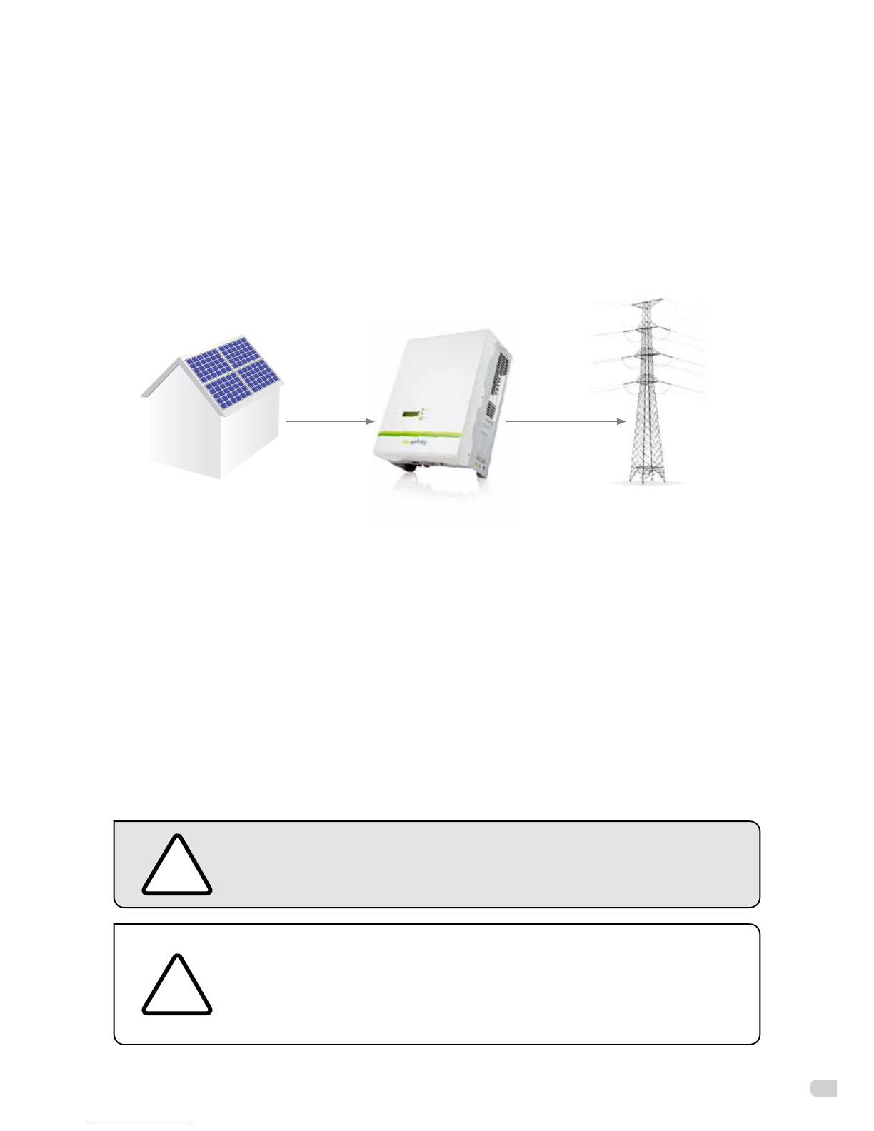
The Enfinity inverter is a PV inverter which converts the DC current of a PV generator into AC current and
feeds it into the public grid.
•PrincipleofasolarpowersystemwiththeEnnityinverter.
PV module inverter grid
Figure 1
The Enfinity inverter may only be operated with PV generators (modules and cabling) of protection class
II. Do not connect any sources of energy other than PV modules to the Enfinity inverter.
When designing the PV system, ensure that the values comply with the permitted operating range of
all components at all times. The free design program ‘Enfinity Design’ will assist you in this process. The
manufacturer of the PV modules must have approved the modules for use with this Enfinity inverter
unit. You must also ensure that all measures recommended by the module manufacturer for long-term
maintenance of the module properties are undertaken.
Do not use the Enfinity inverter for purposes other than those described here. Alternative uses,
modifications to the Enfinity inverter or the installation of components not expressly recommended or
sold by the manufacturer void the warranty claims and operating license.
2.2 Important safety instructions
!DANGER!
Dangertolifeduetohighvoltagesintheinverter!
• Allworkontheinvertermustbecarriedoutbyqualiedpersonnelonly.
!
CAUTION!
Danger of burn injuries due to hot enclosure parts!
During operation, the upper lid of the enclosure and the enclosure body may
become hot.
• Onlytouchthelowerenclosurelidduringoperation.
6
!CAUTION!
Possibledamagetohealthasaresultoftheeectsofradiation!
• Donotstaycloserthan20cmtotheinverterforanylengthoftime.
NOTE:
GroundingthePVgenerator.
Comply with the local requirements for grounding the PV modules and the PV
generator. Enfinity recommends connecting the generator frame and other
electrically conductive surfaces in a manner which ensures continuous conduction
and ground these in order to have optimal protection of the system and personnel.
2.3 Explanation of symbols
This section gives an explanation of all the symbols shown on the inverter and on the type label.
•Symbolsontheinverter
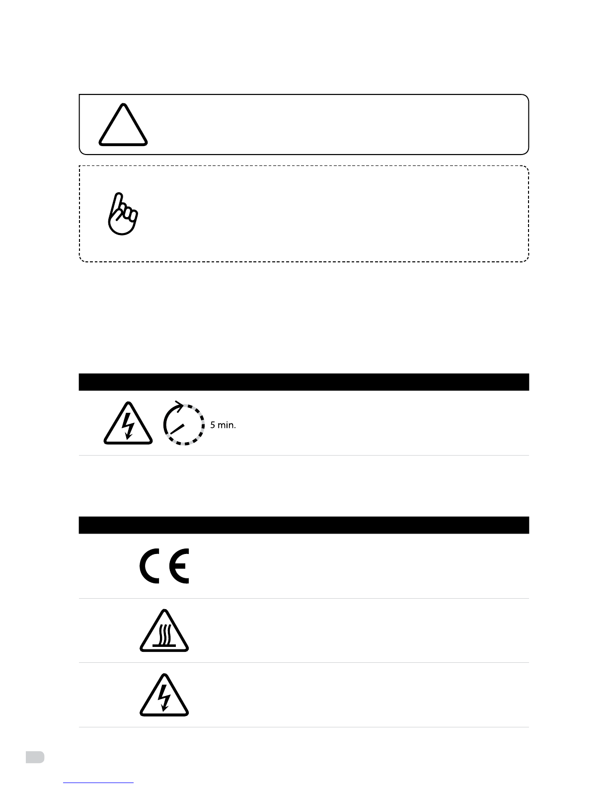
Symbol Explanation
Danger to life due to high voltages in the inverter!
There is residual voltage in the inverter. The inverter requires 5
minutes to discharge.
•Wait 5 minutes before you open the upper lid or the DC lid.
•Symbolsontheproductlabel
Symbol Explanation
CEmark.
The inverter complies with the requirements of the applicable
CE guidelines.
Bewareofhotsurface.
The inverter can become hot during operation. Avoid contact
during operation.
Dangerofhighvoltages.
Danger to life due to high voltages in the inverter!
7
•Importantsafetyinstructions
When using the product, please remember the information detailed below to avoid the risk of fire and
personal injury:
!
WARNING!
Ensure input DC voltage ≤Max.DC voltage. Over voltage may cause permanent
damage to inverter or other losses, which will not be covered by the warranty!
This chapter contains important safety and operating instructions. Read and keep
this operation guide for future reference.
!
WARNING!
Authorized service personnel must disconnect both AC and DC power from the
Enfinity inverter before attempting any maintenance, cleaning or working on any
circuits connected to the Enfinity inverter.
• BeforeusingtheEnnityinverter,readallinstructionsandcautionarymarkingsontheEnnity
inverter, and all appropriate sections of this guide.
• UseonlyattachmentsrecommendedorsoldbyEnnity.Doingotherwisemayresultinariskofre,
electric shock, or injury to persons.
• Toavoidariskofreandelectricshock,makesurethatexistingwiringisingoodconditionandthatthe
wires are not undersized. Do not operate the Enfinity inverter with damaged or substandard wiring.
• DonotdisassembletheEnnityinverter.Itcontainsnouser-serviceableparts.SeeWarrantyfor
instructions on obtaining service. Attempting to service the Enfinity inverter yourself may result in a
risk of electric shock or fire and will void your warranty.
• Toreducetheriskofelectricshock,authorizedservicepersonnelmustdisconnectbothACandDC
power from the Enfinity inverter before attempting any maintenance, cleaning or working on any
circuits connected to the Enfinity inverter. Turning o controls will not reduce this risk.
• Keepawayfromammable,explosivematerialstoavoidredisaster.
• Theinstallationplaceshouldbeawayfromhumidorcorrosivesubstance.
• Toavoidelectricshockaccident,pleasedonotdisassembletheinverterbecausetherearehigh-
voltage capacitors installed inside the inverter. Fatal high-voltage will remain in the inverter after its
disconnection with grid for 5 minutes.
• Toreducethechanceofshort-circuits,authorizedservicepersonnelmustuseinsulatedtoolswhen
installing or working with this equipment.

8
3 Introduction
3.1 Basic features
Congratulations on your purchase of an Enfinity inverter. The Enfinity inverter is one of the finest inverters
on the market today, incorporating state-of-the-art technology, high reliability, and convenient control
features.
• AdvancedMCUcontroltechnology.
• Incorporatingthelatesthigh-eciencypowercomponents.
• OptimalMPPTtechnology.
• Advancedanti-islandingsolutions.
• Excellentprotections.
• IP65protectionlevel.
• Eciencyupto96.6%.
• THD<3%.
• Safe&Reliable:transformerlessdesignwithsoftwareandhardwareprotection.
• FriendlyHMI(Human-MachineInteraction).
• LEDstatusindications.
• LCDdisplaytechnicaldata,Human-Machineinteractionthroughpresskey.
• RS485andRS232communicationinterface.
• PCremotecontrol.
3.2 Electrical block diagram
•Electricalblockdiagram
MPPTDC Input
+
-
DC/DC
Ground Fault
Monitoring
LCD
RS485
MCU
Controller A
MCU
Controller B
AC Leakage
Current
Detection
PE
AC
RS232
DC/AC
MPPTDC Input
+
-
DC/DC
Ground Fault
Monitoring
LCD
RS485
MCU
Controller A
MCU
Controller B
AC Leakage
Current
Detection
PE
AC
RS232
DC/AC
+
-
Figure 2: Enfinity 1000TL-2800TL Figure 3: Enfinity 3300TL-5000TL

9
•TerminalsofPVinverter
Figure 4: terminals of Enfinity 1000TL-2800TL inverters Figure 5: terminals of Enfinity 3300TL-5000TL inverters
!CAUTION!
About SF-SW. Risk of electric shock! Only authorized personnel is allowed to set
the DIP switch (see page 33).
3.3 Dimensions and weight
•Dimension
Figure 6: Enfinity 1000TL-2800TL inverters Figure 7: Enfinity 3300TL-5000TL inverters
•Weight
Enfinity model 1000TL 1650TL 2200TL 2800TL 3300TL 3680TL 4400TL 5000TL
Weight 17.1kg 17.1kg 17.5kg 17.9kg 18.9kg 19.2kg 19.2kg 19.2kg
329mm
433mm
180mm
RS-485RS-485
DC InputDC Input RS-232RS-232 AC OutputAC Output
SF-SWSF-SW
332mm
450mm
161mm

10
4 Technical data
4.1 DC Input
Enfinity model 1000TL 1650TL 2200TL 2800TL 3300TL 3680TL 4400TL 5000TL
Max. DC
Input Power 1100W 1700W 2300W 3000W 3480W 4000W 4580W 5200W
Max. DC Voltage 550V
Max. DC Current 9A 9A 11A 13.5A 17. 5A 22A 22A 26A
MPP Tracking No. 1
MPPT Voltage
Range 120 - 500V 180V - 500V 200V - 500V 210V - 500V 200V - 500V
No. of DC Inputs 1 2
Switch on/o
Voltage 100V / 70V
4.2 AC Output
Enfinity model 1000TL 1650TL 2200TL 2800TL 3300TL 3680TL 4400TL 5000TL
Rated Output
Power 1000W 1500W 2000W 2600W 3000W 3680W 4000W 4600W
Max. Output
Power 1000W 1650W 2200W 2800W 3300W 3680W 4400W 5000W
Max. Output
Current 6A 8.6A 11A 13.8A 16A 16A 22A 24A
On-grid
Connection Single-phase
On-grid AC
Voltage / Range 230V / 180V - 270V
On-grid AC
Frequency / Range 50Hz / 60Hz, 47-52Hz / 57-61,5 Hz
Power Factor 1
THD <3%(Ratedpower)

11
4.3 Eciency, safety and protection
Enfinity model 1000TL 1650TL 2200TL 2800TL 3300TL 3680TL 4400TL 5000TL
Eciency
Max. Eciency 96.6% 96.8% 96.8% 97% 97.4% 97.6% 97.6% 97.6%
Euro Eciency 95% 95.8% 96.2% 96.3% 96.5% 97.1% 97.1% 96.8%
MPPT Eciency 99.9%
Safety and protection
Over voltage
Protection Yes
DC isolation
Impedance
Monitoring
Yes
Ground Fault
Protection Yes
Grid Monitoring Yes
Ground Fault
Current
monitoring
Yes
DC Injection
Monitoring Yes
4.4 General data
Enfinity model 1000TL 1650TL 2200TL 2800TL 3300TL 3680TL 4400TL 5000TL
Dimension
(W/H/D) 332/450/161mm 329/433/180mm
Weight 17.1kg 17.1kg 17.5kg 17.9kg 18.9kg 19.2kg 19.2kg 19.4kg
Installation Wall-mounted
Operating
Temperature
Range
-20°C ~ +60°C (derating at 45°C)
Relative Humidity 0%~95%,nocondensation
Altitude <2,000m
Protection Level IP 65
Isolation Type Transformerless
Night-time
Consumption 0W
Operating Loss <10W
Cooling Natural Cooling Fan Cooling
Noise Level <28dBA <40dBA
Communication
Interface RS485 and RS232
Standard Warranty 10 years

12
5 Function
•Operationmode
Stand-by mode
Thestand-bymodemeansthattheinverterisreadybutstillnotconnectedtothegrid.Underthismode,
it will continue to check if the PV array has enough power to feedback into the grid. When the inverter
passes the dump load test after startup, it will change from stand-by mode to checking mode.
Checking mode
If the inverter passed the dump load test and no error/fault occurs, it starts checking to deliver power.
On-Grid mode
Underthismode,EnnityinvertersconvertthePVarray’sDCintoACandfeedsitbackintothegrid.
!
CAUTION!
The inverter decreases the output power is normal in the condition of thermal
protection, but if this phenomenon occurs frequently, you need to check the
heatsink and the fan, or consider putting the inverter in the place where there
isbetterairow.Ifthefanistoodirty,pleasecleanit,andifoutputpower
decreases, please ask for professional support.
MPPTmode
ThedefaultsettingisMPPTmode,theoperationmodewillreturntoMPPTafterDC&ACrestart.
Fault mode
If any fault or error occurs, the inverter stops delivering power until the fault or error is clear. Some faults
or errors will auto recover, and some may need a manual restart.
Setting mode
The user can access the setting mode by pressing ‘Function’ key for 5 seconds. Please refer to the
operation method in chapter 7 for detailed information.

13
6 Installation
6.1 Packaging
Figure 8: packaging
Object description Quantity Remark
1Enfinity inverter 1
2Bracket 1
3Screw package 1 set screwpackageinclude:M5angenut,expansionscrew,M5screwrivet
4AC connector 1
5DC connector
1 set for ENFINITY-1000TL/1650TL/2200TL
2 sets for ENFINITY-2800TL/3300TL
3 sets for ENFINITY-3680TL/4400TL
4 sets for ENFINITY-5000TL
6T-plug
none for ENFINITY-1000TL/1650TL/2200TL/3300TL
1 set for ENFINITY-2800TL/3680TL/4400TL
2 sets for ENFINITY-5000TL
7Packaging list 1
8Product manual 1
9Warranty terms and
conditions 1
10 Product warranty 1
7 9 10
4
5
31 2
8
6
14
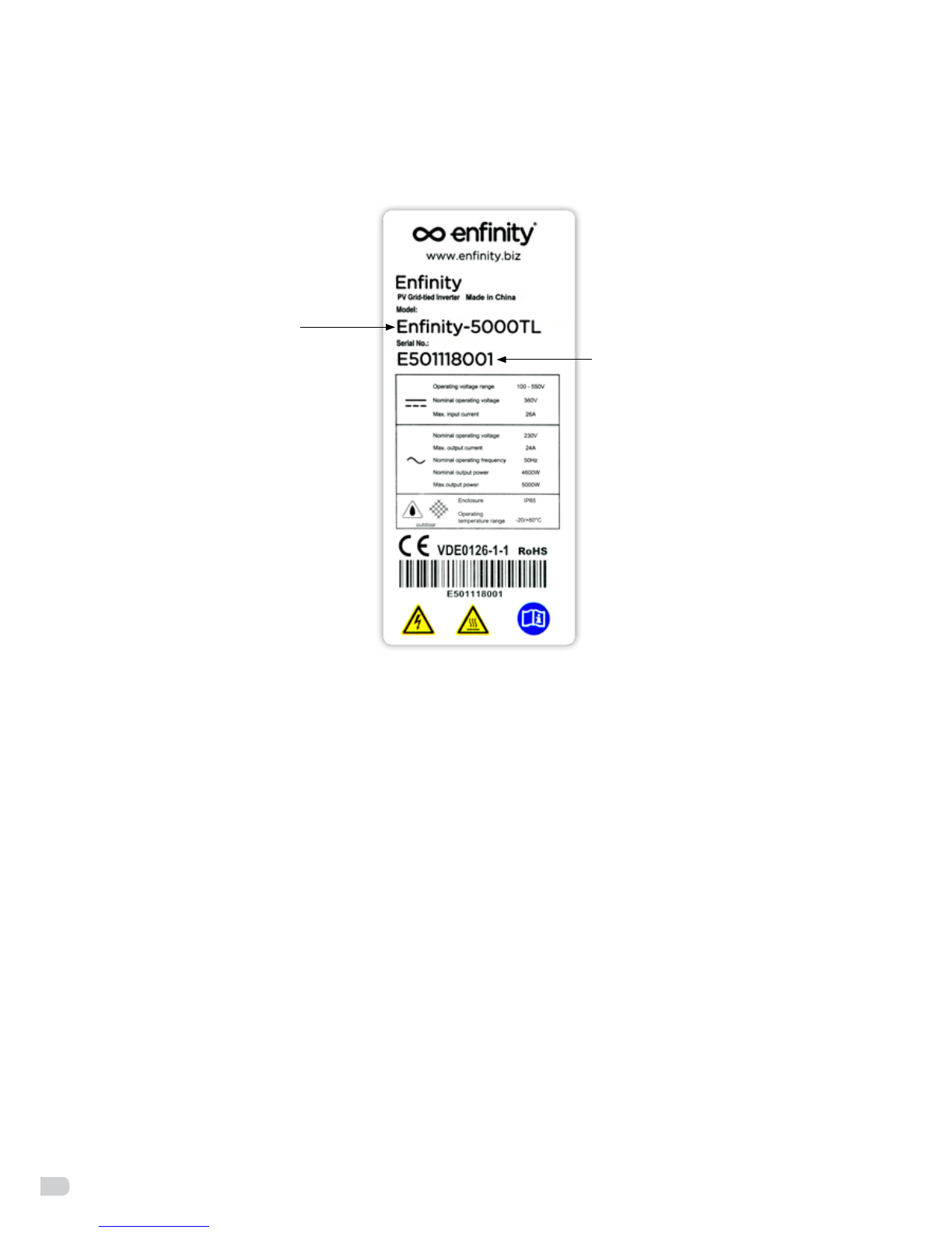
6.2 Identification of the Enfinity inverter
You can identify the Enfinity inverter type by the product label found on the right-hand side of the housing.
6.3 Installation precautions
Check the environment where the system is installed
Check that the installation site does not have any of the following conditions:
• Theambienttemperatureisoutsidetherangeoftolerableambienttemperature
(-20°C to +60°C, -4°F to +140°F,).
• Higherthanthealtitudeofabout2,000mabovesealevel.
• Pronetobedamagedbyseawater.
• Closetocorrosivegasorliquid(forexample,locationswherechemicalsareprocessed).
• Exposedtodirectsunlight.
• Pronetobeoodedorhighlevelsofsnowpack.
• Littleornoairowandhighhumidity.
• Exposedtosteam,vapor,orwater.
• Exposedtodirectcoolair.
• Nearthetelevisionantennaorantennacable.
• Ventilationisinsucienttocooltheinverter,thatistosay,outdoors,theinverterrequiresatleast30
cm (see table and illustration) of clearance around the unit. It is recommended that the same clearance
between the unit and the ground be used. Installing the inverter with inadequate ventilation may cause
the system to malfunction as a result of water or excessive high temperature inside the inverter.
Please advise users that Enfinity will not compensate any fault caused in this way.
• Flammableunderground.
• Don’tinstallongyprocwalltoavoidthenoiseorvibration.
Device type
Serial number
Figure 9: product label
15
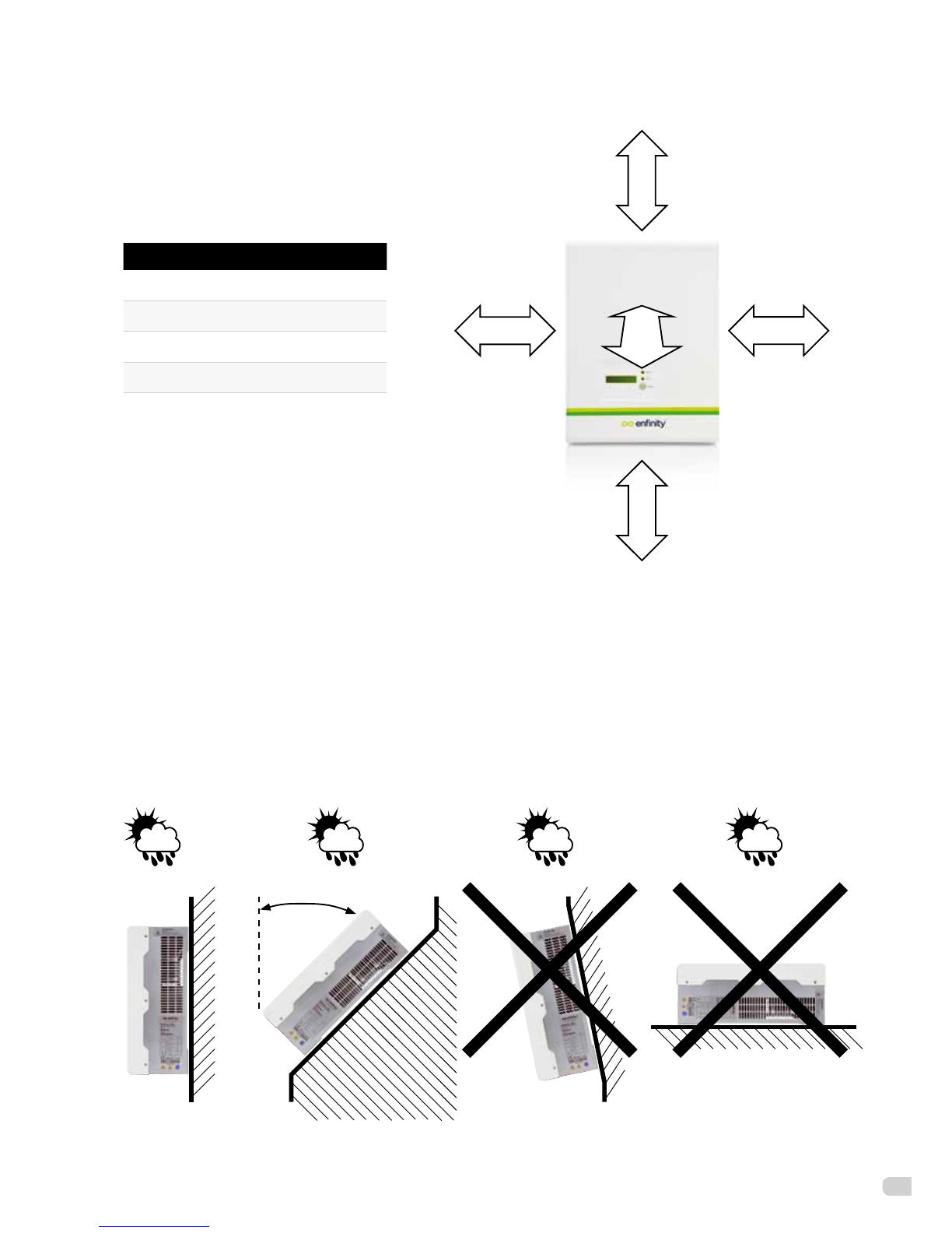
Direction Minimum clearance
Sides 30cm
Top 30cm
Bottom 30cm
Front 10cm
Figure 10: minimum clearance
6.4 Positioning and mounting instructions
• Installverticallyortiltedbackwardsuptoamaximumof45°.
• Neverinstalltheinvertertiltingforward.
• Donotinstallhorizontally.
• Installateyeleveltoallowoperatingmodestobereadatalltimes.
45°
Figure 11: positioning instructions
30cm 30cm
10
cm
30
cm
30
cm
16
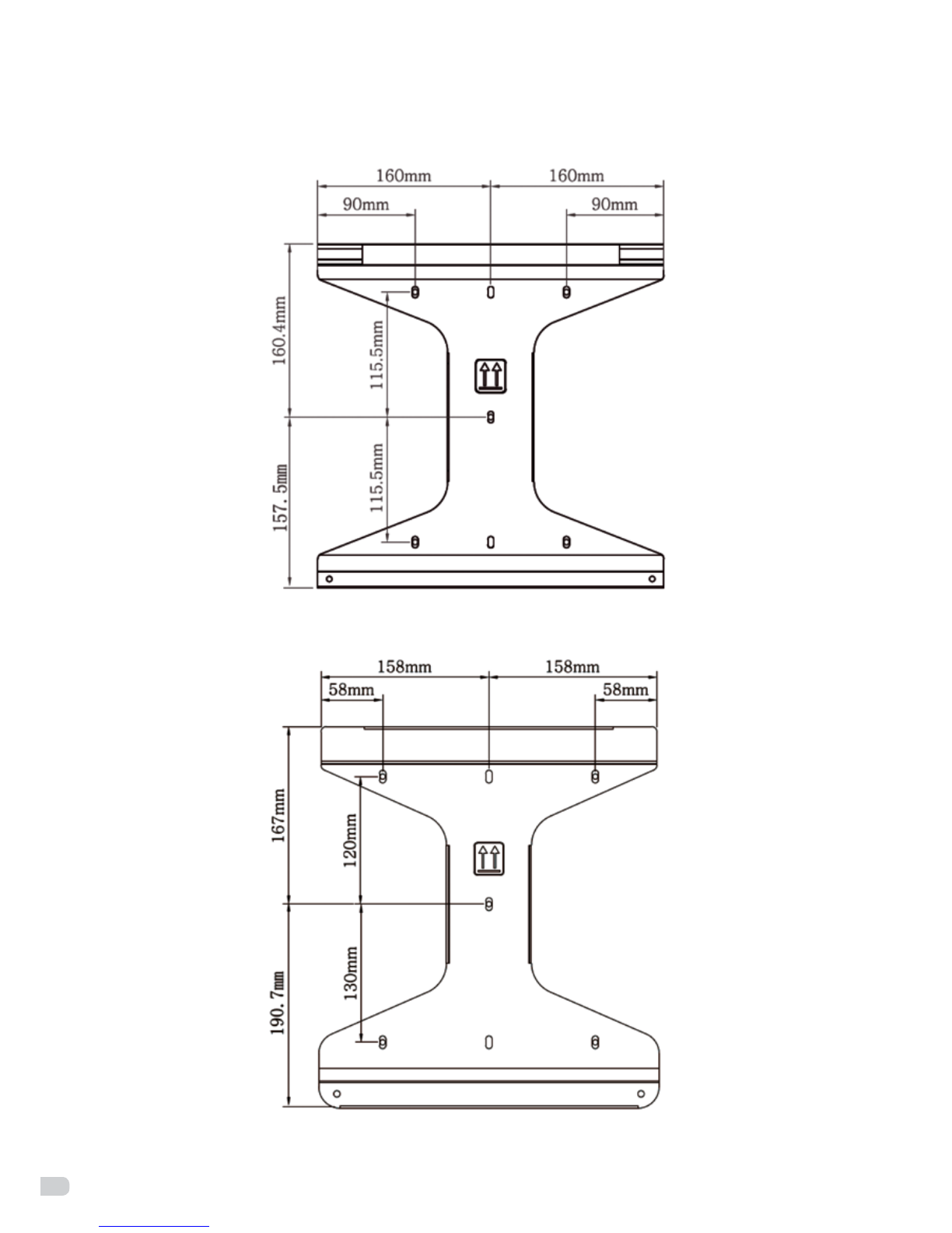
• Usetherearpanelasadrillingtemplateandmarkthepositionsofthedrillholes.
Figure 12: rear panel for the Enfinity 1000TL-2800TL inverters
Figure 12: rear panel for the Enfinity 3300TL-5000TL inverters

17
6.5 Preparation
• Installationtools:crimpingpliersforbindingpostandRJ11, 6 driller, screwdriver and manual wrench.
Figure 13: installation tools
!
WARNING!
Before installation and maintenance, check that both the AC and DC sides do
not carry electricity. If the DC side has just been disconnected, capacitors will
still contain electricity; therefore, please wait for at least 5 minutes to ensure the
capacitors completely release the energy and the inverter is not electrified.
NOTE:
Inverters should be installed by a technician.
6.6 Installation steps
Step 1
Drill 5 holes in the wall with 6 drill piece according to the size of bracket. Keep drilling vertical to the wall,
and don’t shake when drilling to avoid damage to the wall. The depth of the holes should be about 30mm.
After removing the dust in the holes, measure the net depth of the holes. If the depth is deeper than 33mm
or less than 27mm, the expansion tubes should not be installed and tightened.
Figure 14: installation of the expansion pipe
expansion screw
expansion pipe

18
Step 2
Clean all dust outside/inside the hole and measure pitch-row before installation. It needs repositioning
and drilling holes if the hole with much error. Then put expansion pipe into the hole vertically, use rubber
hammer to tap the pipe into the wall completely. After that, twist the 5 screws into 5 corresponding pipes.
Step 3
Usethebrackettoinstalltheinverterontothenarrowverticalpanel(orwall).
Put upper-part holes of the inverter onto the bracket, lower part onto the M5 screw rivet of
the bracket. Srew the 2 nuts on the M5 screw rivet (see figure 15).
Figure 15: installation of the bracket
Step 4
UseM5angenuttoxthebottomoftheinverter.
Step 5
You can connect PV-modules in serie into 1 string for the Enfinity inverters (1000TL/1650TL/2200TL/2800TL)
and 2 strings for the Enfinity inverters (3300TL/3680TL/4400TL/5000TL). Complete the installation process.
6.7 Connection of the PV power system
•PVstring
Please select PV modules with excellent function and reliable quality. Open-circuit voltage of module arrays
connectedinseriesshouldbe<Max.DC(tablebelow)inputvoltageatthemintemperatureaccordingto
the country ex. (-10°C for Belgium); operating voltage should be conformed to MPPT voltage range.
Enfinity model 1000TL 1650TL 2200TL 2800TL 3300TL 3680TL 4400TL 5000TL
Max. DC Voltage 550V
Please use a PV cable to connect modules to the inverter. From junction box to the inverter, voltage drop is
about1-2%.SowesuggesttoinstalltheinverternearthePV-modules,inordertosavecableandreduceDCloss.
5 screws 2 nuts

19
NOTE:
Please do not make the PV panel positive or negative grounded.
Figure 16: use a multimeter to measure module array voltage
!WARNING!
PV module voltage is very high which belongs to dangerous voltage range,
please comply with electric safety rules when connecting.
!WARNING!
When there is something wrong with module arrays, modules can be connected
with PV grid-tied inverter only after eliminating these problems.
20
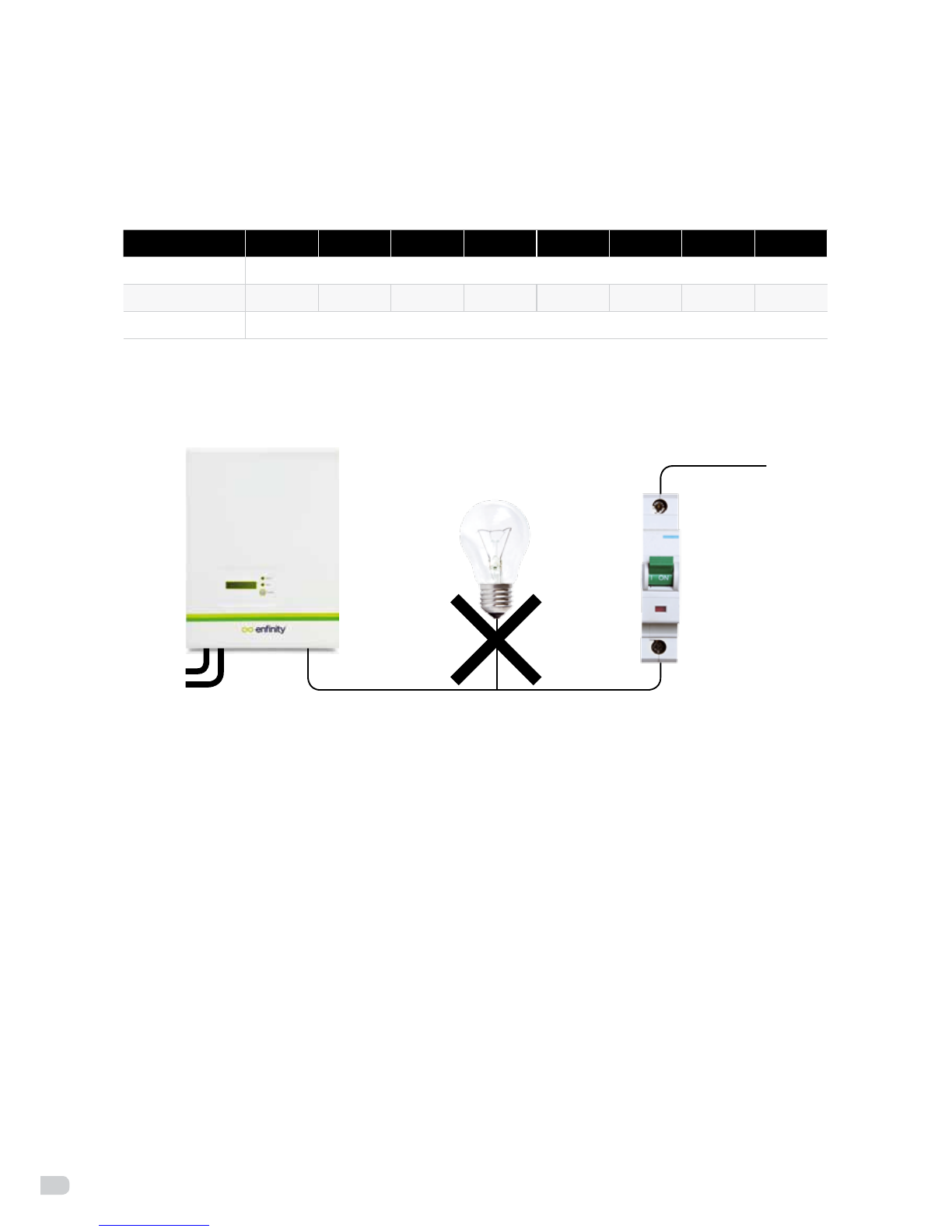
•ACoutput
Enfinity inverters are designed for single phase grid. The Voltage range is from 180V to 260V (200V-270V
for Australia), frequency is 47Hz~52Hz/57Hz~61.5Hz. Other technical requests should comply with the
requirement of local public grid.
Enfinity model 1000TL 1650TL 2200TL 2800TL 3300TL 3680TL 4400TL 5000TL
Cable 4mm2
Micro-Breaker 16A 16A 20A 20A 20A 25A 25A 25A
Distance max. 15m
Micro-breaker should be installed between inverter and grid, and its leakage current needs to be >30mA.
Any load should not be connected with the inverter directly.
Figure 17: incorrect connections between load and inverter
Impedance of the Enfinity inverter AC connecting dot should be less than 2Ω. To ensure reliable anti-
islandingfunction,PVcableshouldbeusedtoensurewireloss<1%ofnormalpower.
This product has a professional IP66 AC waterproof connector. You have to wire AC by yourself. Please
see figure 18 and 19 for AC connector disassembling guide.
This manual suits for next models
7
Table of contents


