SIGLENT SSG5000 Series User manual

SIGLENT
SSA3000X Service Manual 1
SSG5000X
Signal Generator
r
Service Manual
E01A

SIGLENT
2 SSG5000X Service Manual
Guaranty and Declaration
Copyright
SIGLENT TECHNOLOGIES CO., LTD All Rights Reserved.
Trademark Information
SIGLENT is the registered trademark of SIGLENT TECHNOLOGIES CO.,LTD
Declaration
◆SIGLENT products are protected by patent law worldwide
◆SIGLENT reserves the right to modify or change parts of or all the
specifications or pricing policies at company’s sole decision.
◆Information in this publication replaces all previously corresponding
material.
◆Any way of copying, extracting or translating the contents of this manual is
not allowed without the permission of SIGLENT.
◆SIGLENT will not be responsible for losses caused by either incidental or
consequential in connection with the furnishing, use or performance of this
manual as well as any information contained.
Product Certification
SIGLENT guarantees this product conforms to the national and industrial
standards in China as well as the ISO9001: 2015 standard and the ISO14001:
2015 standard. Other international standard conformance certification is in
progress.

SIGLENT
SSG5000X Service Manual 3
General Safety Summary
Carefully read the following safety precautions to avoid any personal
injury or damage to the instrument and any products connected to it. To
avoid potential hazards, please use the instrument as specified.
Use Proper AC Power Line
Only the power cord designed for the instrument and authorized by local
country should be used.
Ground the Instrument
The instrument is grounded through the protective earth conductor of
the power line. To avoid electric shock, please make sure the instrument
is grounded correctly before connecting its input or output terminals.
Connect the Probe Correctly.
If a probe is used, do not connect the ground lead to high voltage since it
has isobaric electric potential as the ground.
Look Over All Terminals’ Ratings
To avoid fire or electric shock, please observe all ratings and label
notices on this instrument. Before connecting the instrument, please
read the manual carefully to gain more information about the ratings.
Use Proper Overvoltage Protection
Make sure that no overvoltage (such as that caused by a thunderstorm)
can enter the product, or else the operator might be exposed to danger of
electrical shock.
Electrostatic Prevention
Operate the instrument in an electrostatic discharge protective area
environment to avoid damages induced by static discharge. Always
ground both the internal and external conductors of the cable to release
static before connecting.
Maintain Proper Ventilation
Inadequate ventilation may cause increasing of the instrument’s
temperature, which will eventually damage the instrument. So keep well
ventilated and inspect the intake and fan regularly.
Avoid Exposed Circuit or Components
Do not touch exposed contacts or components when the power is on.
Do Not Operate Without Covers
Do not operate the instrument with covers or panels removed.
Use Only the Specified Fuse.
Keep Product Surfaces Clean and Dry.
To avoid the influence of dust and/or moisture in the air, please keep the
surface of the device clean and dry.

SIGLENT
4 SSG5000X Service Manual
Do Not Operate in Wet Conditions.
In order to avoid short circuiting to the interior of the device or electric
shock, please do not operate the instrument in a humid environment.
Do Not Operate in an Explosive Atmosphere.
In order to avoid damage to the device or personal injury, it is important
to operate the device away from an explosive atmosphere.

SIGLENT
SSG5000X Service Manual 5
Safety Terms and Symbols
Terms on the product. These terms may appear on the product:
DANGER Indicates direct injuries or hazards that may happen.
WARNING Indicates potential injuries or hazards that may happen.
CAUTION Indicates potential damages to the instrument or other
property that may happen.
Symbols on the product. These symbols may appear on the product:
Hazardous Protective Warning Earth Chassis
Voltage Ground Ground

SIGLENT
6 SSG5000X Service Manual
Contents
Guaranty and Declaration .............................................................................2
General Safety Summary ..............................................................................3
Safety Terms and Symbols ...........................................................................5
Preparation Information ................................................................................7
Power-on Inspection..................................................................................7
Interface Test.............................................................................................8
Performance Verification Test....................................................................15
10 MHz output accuracy test...................................................................16
Absolute amplitude accuracy test............................................................17
Second Harmonics ..................................................................................20
Internal AM modulation test .....................................................................22
Internal FM modulation test.....................................................................24
Internal ΦM modulation test.....................................................................26
Pulse modulation test ..............................................................................28
I/Q modulation distortion performance test..............................................30
I/Q modulation EVM performance test.....................................................32
LF AC test................................................................................................34
LF DC test ...............................................................................................36
Assembly Procedures .................................................................................37
Safety Considerations..............................................................................37
List of Modules ........................................................................................38
Required Tools.........................................................................................38
Disassembly Procedures.........................................................................39
Removing the Outer Cover................................................................39
Removing the IQ Module...................................................................40
Removing the Power Module ............................................................41
Removing the Control Board.............................................................42
Removing the Main Board.................................................................43
Removing the front panel ..................................................................44
Removing the LCD, Keyboard...........................................................45
Contact SIGLENT.........................................................................................46
SIGLENT
SSG5000X Service Manual 7
Preparation Information
Before initiating performance verification or any adjustments, it is
recommended to follow these procedures. The following topics are discussed
in this chapter.
⚫How to perform power-on inspection.
⚫How to perform interface test.
For more detailed information about the signal generator operation, please
refer to the SSG5000X User Manual.
Power-on Inspection
The normal operating voltage for SSG5000X series signal generators is in the
range of 100-240 VRMS, 50 Hz/ 60 Hz/ 440 Hz.
Please use the power cord provided with the accessories to connect the
instrument to the power source as shown in the figure below.
Figure 1-1 Connect power cord
Note: To avoid electric shock, make sure that the instrument is
correctly grounded to the earth before connecting AC power.
Press the power-on button located at the lower left corner of the front panel
and several keys will illuminate for about 6 seconds. Then, the boot screen will
appear on the display.
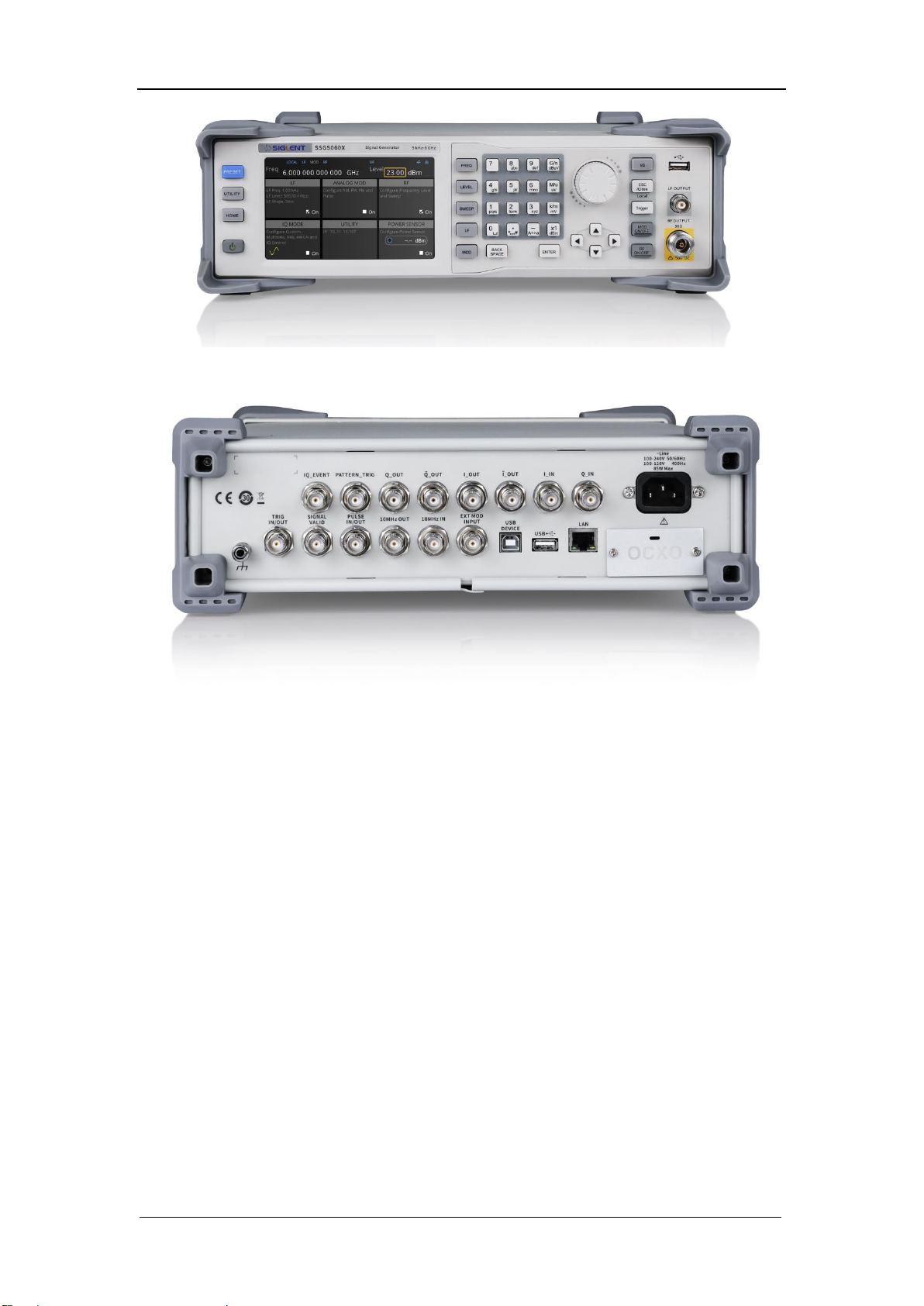
The front panel is shown in the figure below.
Power
Interface
SIGLENT
8 SSG5000X Service Manual
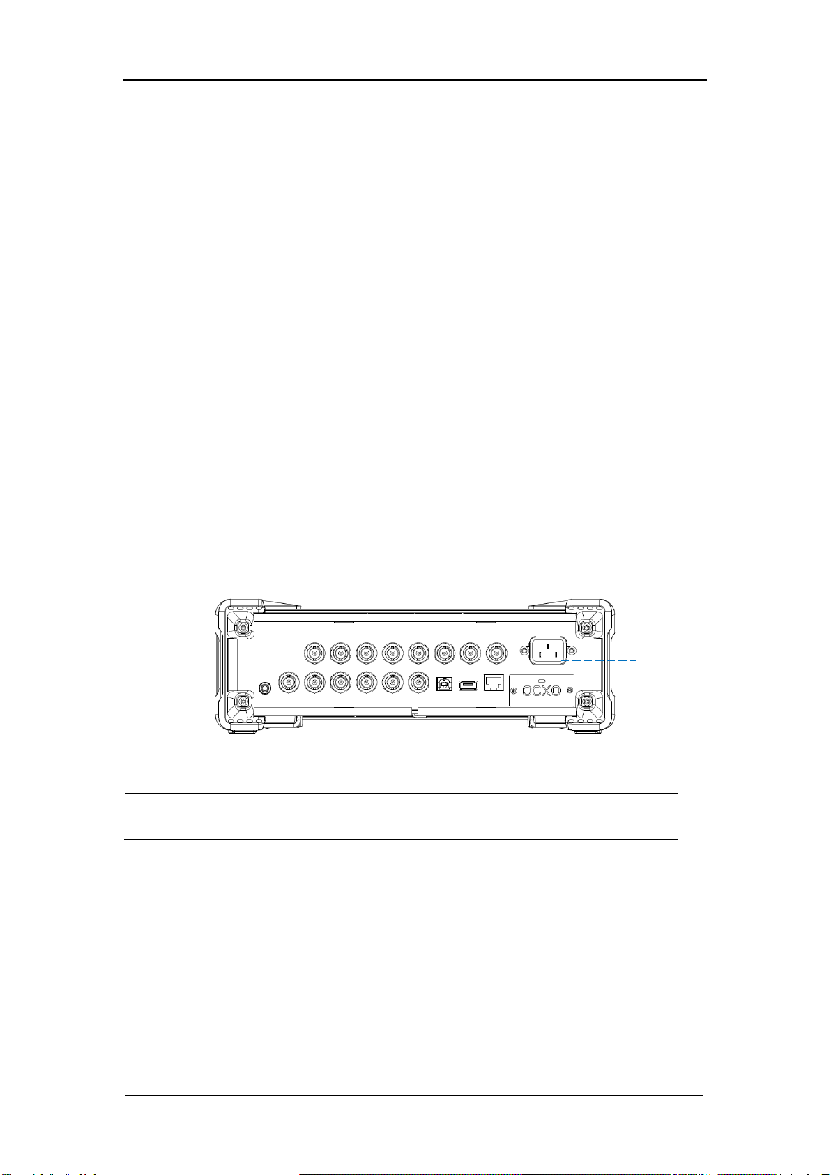
Figure 1-2 Front Panel
Figure 1-3 Rear Panel
Interface Test
The SSG5000X series signal generator is designed with three standard
interfaces: USB Host, USB Device, and LAN. Being connected to other
instruments via these interfaces enables the signal generator to achieve
additional capabilities. In order to ensure the signal generator is operating
properly, it is recommended to first test the interfaces.
USB Host Test
To test if the USB Host interface is working normally.
Tools:
● USB memory device (U disk)
Steps:

SIGLENT
SSG5000X Service Manual 9
1. Insert a U disk into the USB Host interface on the front panel of the signal
generator.
2. An icon shaped like a U disk appears on the upper right of the screen, as
shown in figure below. The icon appearance indicates the U disk has been
successfully recognized.
Figure 2-1 USB drive has been properly recognized
SIGLENT
10 SSG5000X Service Manual
USB Device Test
To test if the USB Device interface is operating normally.
Tools:
●A computer with USB interface that is compatible with running National
Instruments NI-MAX software
● A standard USB cable (Type A-B)
● NI-MAX software
Steps:
1. Download and install National Instruments NI MAX software by following the
installation instructions provided by National Instruments.
2. Connect the signal generator USB Device port and the computer using an
USB cable.
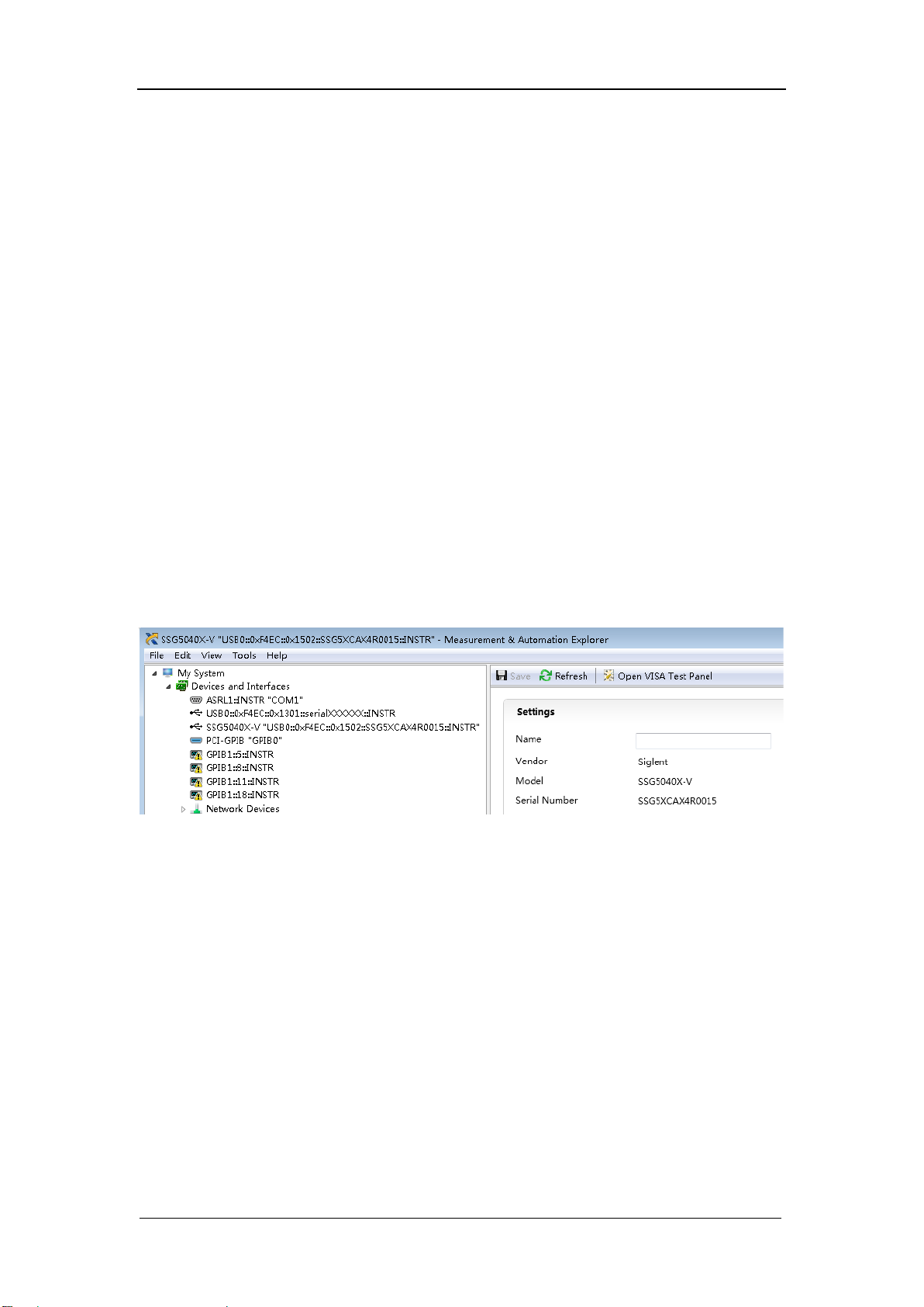
3. Run NI MAX software. Click “Device and interface” at the upper left corner of
the NI software interface and immediately displays the “USBTMC” device
symbol.
4. Click “Open VISA Test Panel” option button, and then the following
Interface will appear. Then click the “Input/Output” option button and click
the “Query” option button in order to view the Read operation information.

SIGLENT
SSG5000X Service Manual 11

SIGLENT
12 SSG5000X Service Manual
LAN Port Test
Use to test the LAN interface functionality.
Tools:
● A computer with functional LAN interface
● A standard LAN cable
Steps:
1. Connect the signal generator and the computer using a LAN cable via LAN
interface.
2. Press UTILITY->Interface, Set DHCP State ON, as the figure below shows.
The signal generator will set IP Address and Subnet Mask and Gateway
automatically in this network.
3. Write down the displayed IP address. It will be used in later steps.
Figure 2-2 IP configuration interface
4. Run NI max software. Click “Device and interfaces” in the upper left corner
of the NI software interface, select “Network Devices”, Add Network Device,
and select VISATCP/IP Resource as shown:.

SIGLENT
SSG5000X Service Manual 13
5. Select Manual Entry of LAN instrument, select Next, and enter the IP
address as shown. Click Finish to establish the connection:
Note: Leave the LAN Device Name BLANK or the connection will fail.

SIGLENT
14 SSG5000X Service Manual
6. After a brief scan, the connection should be shown under Network
Devices:
7. Right-click on the product and select Open NI-VISATest Panel:
8. Click the “Input/Output” option button and click the “Query” option button in
order to view the Read operation information.
Note: The *IDN? Command (known as the Identification Query) should return the
instrument manufacturer, instrument model, serial number, and other
identification information.

SIGLENT
SSG5000X Service Manual 15
Performance Verification Test
This chapter explains testing the signal generator in order to verify
performance specifications. For accurate test results, please let the test
equipment and the signal generator warm up 30 minutes before testing.
Below is the required equipment:
Table 3-1 Test equipment
Equipment
Specification
Qty.
Recommended
Signal Analyzer
20Hz~26.5 GHz
1
Keysight N9020
Power Meter
6 GHz
1
R&S NRP6A
Frequency
Counter
10 MHz
1
SIGLENT
SDG6032X
With OCXO
Dual-N Cable
6 GHz
1
BNC Cable
2 GHz
1

SIGLENT
16 SSG5000X Service Manual
10 MHz output accuracy test
Specification
Reference frequency
10.000000 MHz
Initial calibration accuracy
<0.2 ppm
Test Connection Diagram
Test Procedures
1. Connect ref out port of the signal generator to the channel A of the
SDG6000X. The SDG6000X should be connected to an external OCXO 10
MHz reference oscillator.
2. Set the SDG6000X to frequency counter mode, and set frequency ref to
10.000000 MHz
3. Check if the frequency deviation ≤ 0.2 ppm
Test Record Form
Frequency
Frequency Deviation
Pass/Fail
10.000000 MHz

SIGLENT
SSG5000X Service Manual 17
Absolute amplitude accuracy test
Specification
Level error (ALC on, temperature is 20 ℃~30 ℃)
Max performance
power to -40 dBm
-40 dBm ~ -90
dBm
-90 dBm ~ -110
dBm
-110 dBm ~ -130
dBm
9 kHz≤f<100 kHz
≤0.9 dB
≤0.7 dB (typ.)
≤0.9 dB
≤0.7 dB (typ.)
≤1.1 dB
100 kHz≤f≤4 GHz
≤0.7 dB
≤0.5 dB (typ.)
≤0.7 dB
≤0.5 dB (typ.)
≤1.1 dB
≤0.7 dB (typ.)
≤1.1 dB (typ.)
4 GHz<f≤6 GHz
≤0.7 dB
≤0.5 dB (typ.)
≤0.7 dB
≤0.5 dB (typ.)
≤1.1 dB
≤0.7 dB (typ.)
≤1.2 dB (typ.)
Test Devices
1. Power Meter ×1
2. Dual-N Cable ×1
3. Dual-BNC Cable ×1
4. Signal generator ×1
Test Connection Diagram
(a)
(b)

SIGLENT
18 SSG5000X Service Manual
Figure 3-1 Absolute amplitude accuracy connections
Test Procedures
1. Connect the output terminal of the SSG5000X with the power meter, as
shown in Figure 3-1 (a).
2. Set the SSG5000X to output a sine waveform with -10 dBm amplitude. Then
modify the output frequency of the SSG5000X according to Table 3-2 and
enable the RF output switch RF.
3. Modify the frequency of the power meter accordingly each time the output
frequency of the SSG5000X is modified. Read the amplitude measurement
value A1 and record it to the test record form.
4. Disconnect the SSG5000X and the power meter. Connect the [10 MHz OUT]
terminal of the signal analyzer with the [EXT REF IN] terminal at the rear panel
of the signal generator using dual-BNC cable to synchronize the two
instruments.
5. Connect the output terminal of the SSG5000X with the input terminal of the
signal analyzer using dual-N cable as shown in Figure 3-1 (b).
6. Configure the signal analyzer:
1) Select the external frequency reference input.
2) Set the span to 100 Hz.
3) Set the reference level to -20 dBm.
4) Set the input attenuation to 10 dB.
5) Set the resolution bandwidth to 1 Hz.
6) Set the self-calibration to normal and perform all of the calibration
items.
7. Set the output frequency of the SSG5000X and the center frequency of the
signal analyzer according to Table 3-2 (the center frequency of the signal
analyzer corresponds to output frequency of the SSG5000X).
8. Each time the center frequency is changed, wait for the instrument to finish a
sweep and press Peak Search to find the maximum peak. Then record the
result A2 to the test record form.
9. System Error (the input attenuation of the signal analyzer is 10 dB) = A2 -
A1 and record the measurement result.
10. Keep the connection shown in Figure 3-1 (b) unchanged, press Mode
Preset to restore the signal analyzer to its factory setting and set the output
amplitude of the SSG5000X according to Table 3-3.
11. Each time the output amplitude is changed, set the output frequency of the
SSG5000X and the center frequency of the signal analyzer according to Table
3-2 (the center frequency of the signal analyzer corresponds to output
frequency of the SSG5000X).
12. Each time the center frequency is changed, wait for the instrument to finish
a sweep; then, press Peak Search to find the maximum peak and record the
measurement result A3 to the test record form.
Note: when the output amplitude of the SSG5000X is -10 dBm, the
measurement result A3, namely, is the measurement value A2 of the signal
analyzer in step 8.
13. Calculate the Global Error = A3 - Reference Value and record the result.
14. Calculate the amplitude accuracy using the formula Amplitude Accuracy
= |Global Error - System Error| and compare the calculation result with the
specification.
SIGLENT
SSG5000X Service Manual 19
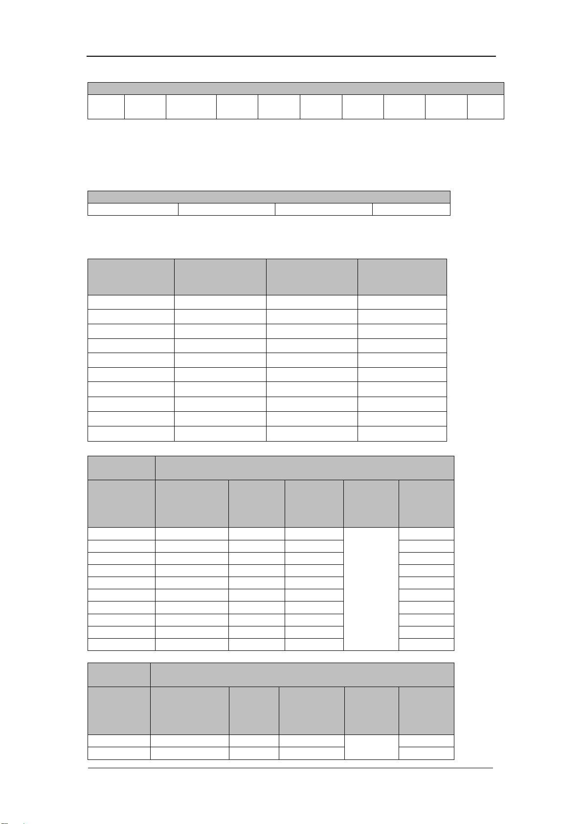
Table 3-2 Output Frequency of the SSG5000X
Output Frequency
103k
Hz
1.33M
Hz
51.33M
Hz
533M
Hz
1.933
GHz
2.433
GHz
2.933
GHz
3.933
GHz
4.933
GHz
5.933
GHz
Note: When the frequency of the signal measured is less than 10 MHz, make certain the
signal analyzer is in the DC coupling mode to ensure the measurement accuracy.
Table 3-3 Output Amplitude of the SSG5000X
Output amplitude
-10 dBm
-50 dBm
-90 dBm
-120 dBm
Test Record Form
SSG5000X
Output
Frequency
Power Meter
Measurement
Value A1
Signal Analyzer
Measurement
Value A2
System
Error
103 kHz
1.33 MHz
51.33 MHz
533 MHz
1.933 GHz
2.433 GHz
2.933 GHz
3.933 GHz
4.933 GHz
5.933 GHz
Reference
Value
-10 dBm
SSG5000X
Output
Frequency
Signal
Analyzer
Measurement
Value A3
Global
Error
Amplitude
Accuracy
Limit
Pass/Fail
103 kHz
<0.7
1.33 MHz
51.33 MHz
533 MHz
1.933 GHz
2.433 GHz
2.933 GHz
3.933 GHz
4.933 GHz
5.933 GHz
Reference
Value
-50 dBm
SSG5000X
Output
Frequency
Signal
Analyzer
Measurement
Value A3
Global
Error
Amplitude
Accuracy
Limit
Pass/Fail
103 kHz
1.33 MHz

SIGLENT
20 SSG5000X Service Manual
51.33 MHz
<0.7
533 MHz
1.933 GHz
2.433 GHz
2.933 GHz
3.933 GHz
4.933 GHz
5.933 GHz
Reference
Value
-90 dBm
SSG5000X
Output
Frequency
Signal
Analyzer
Measurement
Value A3
Global
Error
Amplitude
Accuracy
Limit
Pass/Fail
103 kHz
<0.7
1.33 MHz
51.33 MHz
533 MHz
1.933 GHz
2.433 GHz
2.933 GHz
3.933 GHz
4.933 GHz
5.933 GHz
Reference
Value
-120 dBm
SSG5000X
Output
Frequency
Signal
Analyzer
Measurement
Value A3
Global
Error
Amplitude
Accuracy
Limit
Pass/Fail
103 kHz
<1.1
1.33 MHz
51.33 MHz
533 MHz
1.933 GHz
2.433 GHz
2.933 GHz
3.933 GHz
4.933 GHz
<1.2
5.933 GHz
Second Harmonics
Specification
Spectral purity
Harmonics
CW mod, 1 MHz<f<6 GHz, Level ≤+13 dBm
<-30 dBc
Test Devices
Table of contents
Other SIGLENT Inverter manuals

SIGLENT
SIGLENT SDG5000 series User manual

SIGLENT
SIGLENT SDG800 Series User manual

SIGLENT
SIGLENT SDG5000 series User manual

SIGLENT
SIGLENT SDG6000X Series:SDG6022X User manual

SIGLENT
SIGLENT SDG1000X Series User manual

SIGLENT
SIGLENT SDG2042X User manual

SIGLENT
SIGLENT SDG2000X Series User manual

SIGLENT
SIGLENT UM0202X-E02C User manual

SIGLENT
SIGLENT SSG3000X User manual
Popular Inverter manuals by other brands


SMA
SMA SUNNY BOY 3000 installation manual

SMA
SMA SUNNY BOY 3000TL Single Tracker Quick reference guide

Photonic Universe
Photonic Universe 10A dual battery solarcharging kit instruction manual

PNI
PNI CBM-2 user manual

SunSynk
SunSynk ECCO SUN-3.6K-SG05LP1-EU user manual

Host
Host HIV10GH1P116 Product instruction manual


