EngA Engineered Air XES-SC Series User manual
A
IOM-58 June 14 R5
INSTALLATION, OPERATION
AND MAINTENANCE MANUAL
FOR
XES-SC SERIES
INDOOR INDIRECT GAS FIRED
SEPARATED COMBUSTION HEATING UNIT
UNIT MODEL NO. _________________
UNIT SERIAL NO. _________________
SERVICED BY: ___________________
TEL. NO: ________________________
CANADIAN
HEAD OFFICE
AND FACTORY
USA
HEAD OFFICE
AND FACTORY
CANADIAN
FACTORY
1401 HASTINGS CRES. SE
CALGARY, ALBERTA
T2G 4C8
Ph: (403) 287-4774
Fx: 888-364-2727
32050 W. 83rd STREET
DESOTO, KANSAS
66018
Ph: (913) 583-3181
Fx: (913) 583-1406
6130 97th STREET
EDMONTON, ALBERTA
T6E 3J4
Ph: (780) 430-0310
Fx: (780) 434-6272
SALES OFFICES ACROSS CANADA AND USA
Retain instructions with unit and maintain in a legible condition.
Please give model number and serial number when contacting
factory for information and/or parts.
www.engineeredair.com

A XES SC MANUAL
IOM-58 2 of 30 June 14 R5
TABLE OF CONTENTS
You Have Responsibilities Too .....................................................................................................................................................3
Introduction .................................................................................................................................................................................3
Warranty ......................................................................................................................................................................................5
Parts .............................................................................................................................................................................................6
Receiving ......................................................................................................................................................................................6
Temporary Storage.......................................................................................................................................................................6
Installation....................................................................................................................................................................................7
Codes............................................................................................................................................................................................7
Minimum Clearance For Service And To Combustibles ...............................................................................................................8
Mounting......................................................................................................................................................................................8
Shipping Materials........................................................................................................................................................................9
Suitable Locations ........................................................................................................................................................................9
Assembly Of Two Piece Xess ........................................................................................................................................................9
Separated Combustion...............................................................................................................................................................10
Combustion Air Duct ..................................................................................................................................................................11
Venting Products Of Combustion...............................................................................................................................................12
Natural Gas And Propane Installation........................................................................................................................................18
Gas Line Testing (External To The Unit) .....................................................................................................................................18
Electrical Installation ..................................................................................................................................................................18
Split Unit Wiring .........................................................................................................................................................................19
Recommended 24v Field Wiring Size: ........................................................................................................................................20
Duct Mounted Te-6000-Ea3 Temperature Sensor .....................................................................................................................21
Before Start-Up ..........................................................................................................................................................................21
Start-Up Check List .....................................................................................................................................................................21
Operation ...................................................................................................................................................................................23
Combustion And Final Unit Check For Units Without Trac Controls..........................................................................................23
Unit Shut-Down Instructions......................................................................................................................................................24
Service Shut Down .....................................................................................................................................................................24
Maintenance ..............................................................................................................................................................................25
Electrical.....................................................................................................................................................................................25
Operating Instructions ...............................................................................................................................................................25
Belt Adjustment .........................................................................................................................................................................26
Set Screws ..................................................................................................................................................................................26
Bearing Setscrew Torques..........................................................................................................................................................26
Fan Lubrication...........................................................................................................................................................................27
Motor Lubrication ......................................................................................................................................................................27
Inspection And Cleaning.............................................................................................................................................................27
Filters..........................................................................................................................................................................................27
Controls......................................................................................................................................................................................27
Outdoor Air Intakes, Mixing Sections And Dampers..................................................................................................................28
Safety Shutoff Valve Leak Test:..................................................................................................................................................28
Troubleshooting .........................................................................................................................................................................29
Start-Up Record..........................................................................................................................................................................30
© Airtex Manufacturing Partnership. All rights reserved.

A XES SC MANUAL
IOM-58 3 of 30 June 14 R5
YOU HAVE RESPONSIBILITIES TOO
This installation, operation and maintenance manual cannot cover every possibility, situation or
eventuality. Regular service, cleaning and maintaining the equipment is necessary. If you are not capable
of performing these tasks, hire a qualified service specialist. Failure to perform theses duties can cause
property damage and/or harm to the building occupants and will void the manufacturers’ warranty.
INTRODUCTION
Engineered Air units are high quality products designed and manufactured to provide many years of
trouble-free operation. Engineered Air recommends that is manual be read thoroughly to ensure proper
installation, efficient operation and proper maintenance of this equipment. The submittal record is
considered to be part of the Installation, Operation and Maintenance Manual. Please report any
omissions to the national service manager.
SAFETY PRECAUTIONS
Read, understand and follow the complete manual before beginning the installation, including all safety
precautions and warnings.
WARNING:
FIRE OR EXPLOSION HAZARD
Failure to follow safety warnings exactly could result in serious injury, death or property damage.
Be sure to read and understand the installation, operation and service instructions in this manual.
Improper installation, adjustment, alteration, service or maintenance can cause serious injury, death or
property damage.
—Do not store or use gasoline or other flammable vapors and liquids in the vicinity of this or any other
appliance.
—WHAT TO DO IF YOU SMELL GAS
Do not try to light any appliance.
Do not touch any electrical switch; do not use any phone in your building.
Leave the building immediately.
Immediately call your gas supplier from a phone remote from the building. Follow the gas
supplier’s instructions.
If you cannot reach your gas supplier, call the fire department.
—Installation and service must be performed by a qualified installer, service agency or the gas supplier.
A XES SC MANUAL
IOM-58 4 of 30 June 14 R5
Warning:
Pool, laundry and common cleaning products often contain fluorine or chlorine
compounds. When these chemicals pass through the heater, they can form strong acids.
The acid can eat through the heat exchanger wall, causing serious damage and
presenting a possible threat of flue gas spillage into the building.
Warning:
This unit is connected to high voltages. Electrical shock or death could occur if
instructions are not followed. This equipment contains moving parts that can start
unexpectedly. Injury or death could occur if instructions are not followed. All work
should be performed by a qualified technician. Always disconnect and lock out power
before servicing. DO NOT bypass any interlock or safety switches under any
circumstances.

A XES SC MANUAL
IOM-58 5 of 30 June 14 R5
WARRANTY
LIMITED WARRANTY
ENGINEERED AIR will furnish without charge, F.O.B. factory, freight collect, replacement parts for, or
repairs to products covered herein which prove defective in material or workmanship under normal and
proper use for a period of twelve (12) months from the initial start-up or eighteen (18) months from the
date of shipment, whichever expires sooner, provided the customer gives ENGINEERED AIR written notice
of such defects within such time periods and provided that inspection by ENGINEERED AIR establishes the
validity of the claim and all pertinent invoices have been paid in full. The repairs or replacements will be
made only when the complete product(s) or part(s) claimed to be defective are returned to ENGINEERED
AIR or a depot designated by ENGINEERED AIR, transportation charges prepaid. Repairs or replacements
as provided for by this paragraph shall constitute fulfillment of all ENGINEERED AIR's obligations with
respect to this warranty. The refrigerant charge is not included in any part of this warranty. This warranty
does not apply to any products or parts thereof that have been subject to accident, misuse or
unauthorized alterations, or where ENGINEERED AIR's installation and service requirements have not been
met.
The foregoing warranty is in lieu of all other warranties, express or implied. ENGINEERED AIR specifically
disclaims any implied warranty of merchantability and/or fitness for purpose. Under no circumstances
shall ENGINEERED AIR be liable to, nor be required to indemnify, Buyer or any third parties for any claims,
losses, labour, expenses or damages (including special, indirect, incidental, or consequential damages) of
any kind, resulting from the performance (or lack thereof) of this Agreement or the use of, or inability to
use the goods sold hereunder, including, but not limited to, damages for delay, temporary heating/cooling
costs, loss of goodwill, loss of profits or loss of use. Furthermore, the parties agree that the Buyer's sole
remedy under this Agreement shall be limited to the limited warranty set forth in the preceding paragraph
relating to the repair or replacement of any defective goods. Under no circumstances shall any claim or
award against ENGINEERED AIR exceed the original contract price whether awarded through arbitration,
litigation or otherwise.
ENGINEERED AIR Warranty is void if:
1. The unit is not installed in accordance with this manual.
2. The start-up and operation of the unit is not performed in accordance with this manual.
3. The unit is operated in an atmosphere containing corrosive substances.
4. The unit is allowed to operate during building construction.
5. The unit is allowed to operate in atmospheres where chlorine or chlorine compounds are present
or which contain any contaminant (silicone, aluminum oxide etc.) that adheres to the spark ignition
flame sensing probe.
A XES SC MANUAL
IOM-58 6 of 30 June 14 R5
PARTS
WARNING:
Any replacement part must be of equivalent listing or certification and be functionally
equivalent. The replacement part must meet the original’s specification in terms of
functionality including certifications, timing, input and output range, accuracy and
operation.
Failure to replace parts or components with equivalent parts can cause property
damage, injury or death.
1. Motors:
Motor manufacturers have service centers that will repair or replace motors as required.
2. Parts Other Than Motors:
Contact the nearest Engineered Air sales office or factory. Be sure to include Model Number, Serial
Number, date of installation and nature of failure along with the description of the parts required.
Some parts may not be stocked items that must be made or ordered.
RECEIVING
Refer to the back of the packing slip for receiving unit instructions.
On receipt of the unit, check for damage. Inspect protective covers for punctures or other signs that there
may be internal damage. Remove protective covers and check for internal damage. Replace covers if the
unit is not being assembled or installed at this time. Open access doors and check for internal damage.
Close access doors when the inspection is complete.
All units are pre-tested at the factory immediately prior to shipping and are ensured to be in good
operating condition at that time. If damage is found follow the instructions on the packing slip.
On receipt of the unit, check electrical characteristics (see rating plate) to make sure the unit voltage is
compatible with that available for the unit. All parts for field installation are listed on the shipping order
form.
TEMPORARY STORAGE
If a unit is to be stored prior to installation the following precautions are required:
•Store in a well drained area that will not accumulate surface water.
•Store in an area where the unit will not get damaged.
•The entire perimeter and any full height cross members of the unit must be supported by a level
surface and the supporting surface must be adequate for supporting the entire weight of the unit.
•All protective coverings that were provided for shipping must be in place.
•Protect from rain and snow.

A XES SC MANUAL
IOM-58 7 of 30 June 14 R5
INSTALLATION
Warning:
This unit is not rated for hazardous locations and cannot be installed in areas requiring
any hazardous location rating.
Caution:
All wiring, piping and fuel line installation must be completed by qualified persons in
accordance with all federal, state, provincial and/or local codes.
Note: Installation shall be in accordance with this manual and all other associated component and
control Installation, Operation and Maintenance Manuals.
CODES
In Canada:
1. The installation of this unit shall be in accordance with the latest edition of the Canadian Electrical
Code, Part 1 –C.S.A. Standard C22.1, Provincial and Local Codes, and in accordance with the local
authorities having jurisdiction.
2. This unit shall be electrically grounded in accordance with the latest edition of the Canadian
Electrical Code, Part 1 –C.S.A. Standard C22.1, Provincial and Local Codes, and in accordance with
the local authorities having jurisdiction.
3. The installation of this unit shall be in accordance with the latest edition of the Canadian Natural
Gas and Propane Installation Code, C.S.A. Standard B149.1, Provincial and Local Codes, and in
accordance with the local authorities having jurisdiction.
4. In accordance with local authorities having jurisdiction or CSA. Standard B149.1 a readily accessible
approved manual shut-off valve shall be installed in either the drop or riser as close as possible to
the valve train (gas manifold).
5. The installation of this unit shall be in accordance with the latest edition of the National Plumbing
Code of Canada, Provincial and Local Codes, and in accordance with the local authorities having
jurisdiction.
6. The installation of this unit shall be in accordance with all other National, Provincial and Local
Codes, and in accordance with the local authorities having jurisdiction.
In USA:
1. The installation of this unit shall be in accordance with the latest edition of the National Electrical
Code (ANSI/NFPA 70), State and Local Codes and in accordance with the local authorities having
jurisdiction.
A XES SC MANUAL
IOM-58 8 of 30 June 14 R5
2. This unit shall be electrically grounded in accordance with the latest edition of the National
Electrical Code (ANSI/NFPA 70), State and Local Codes and in accordance with the local authorities
having jurisdiction.
3. If the unit has not been provided with an electric disconnect switch, one of adequate ampacity
shall be installed in accordance with Article 430 of the National Electrical Code (ANSI/NFPA 70).
4. The installation of this unit shall be in accordance with the latest edition of the National Fuel Gas
Code ANSI/Z223.1/NFPA 54, State and Local Codes and in accordance with the local authorities
having jurisdiction.
5. In accordance with local authorities having jurisdiction or NFPA 54 an accessible approved manual
shutoff valve shall be installed within 6 ft (1.8 m) of the valve train (gas manifold).
6. The installation of this unit shall be in accordance with the latest edition of the National Standard
Plumbing Code (NSPC), State and Local Codes and in accordance with the local authorities having
jurisdiction.
7. The installation of this unit shall be in accordance with all other National, State and Local Codes,
and in accordance with the local authorities having jurisdiction.
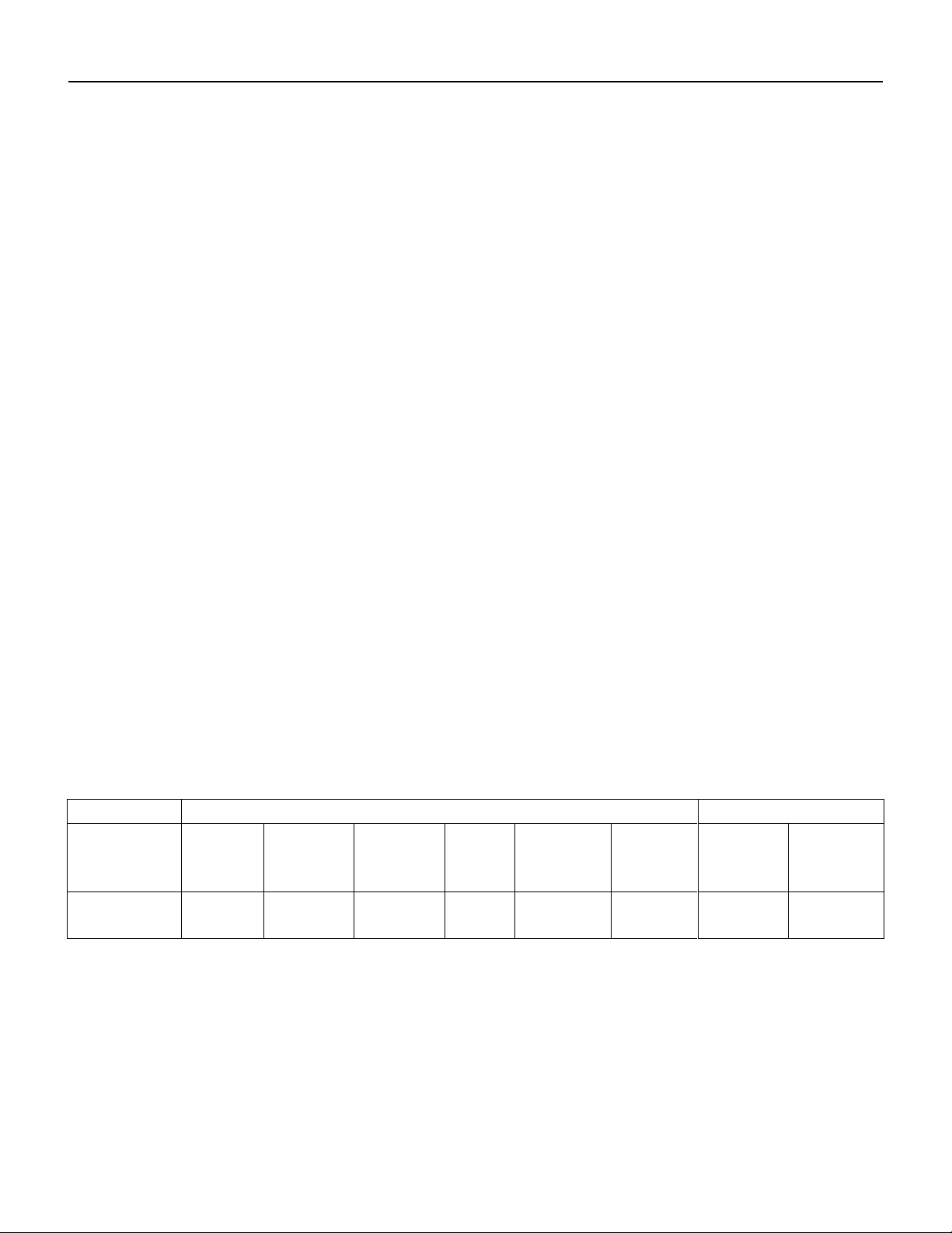
MINIMUM CLEARANCE FOR SERVICE AND TO COMBUSTIBLES
For Safety and Service, the following minimum clearances on the units shall be observed, in inches (mm):
Heaters must be installed to meet at least the minimum clearances shown on the rating plate. The rating
plate is located in the burner compartment. Be sure to allow enough clearance in front of the unit for
removing the burners and above for removing fan motors and blades.
MODEL
COMBUSTIBLE CLEARANCE
SERVICE CLEARANCE
TOP
FRONT
BACK
SIDE
BOTTOM
FLUE
SERVICE/
BURNER
SIDE
CONTROL
PANEL Þ
XES
1" (25)
6" (152)
0
0
C‡
6" (152)
24"
(610)
42”
(1068)
Þ - As required by the Canadian Electrical Code or the National Electrical Code.
* - Service Clearance For Burner & Blower Access, 24" (610).
‡- XES with suffix CF on combustible floor requires special base Part# CB(2,3,4,5,7,8, & 10).
MOUNTING
Units must be mounted level. Failure to do so can cause operational problems that can void warranty.
Failure to do so can result in injury or death, damage to the equipment and/or building and can be a cause
of poor indoor air quality. Equipment must be installed so that sufficient working clearance and
component access is provided. Consult the Submittal Record for specific unit mounting.

A XES SC MANUAL
IOM-58 9 of 30 June 14 R5
SHIPPING MATERIALS
Remove shipping materials. Shipping materials may include, but are not limited to:
-Protective covers over openings, inlets etc.
-Protective covers over split sections if provided.
-Tie-down bolts, straps and blocks on fan vibration isolators.
-Indirect fired heat exchangers may be supported with wood for shipping. Remove.
SUITABLE LOCATIONS
These appliances are suitable for use in aircraft hangars, parking structures and repair garages when
marked and installed, as applicable, in accordance with:
-Standard on Aircraft Hangars, ANSI/NFPA 409
-Standard for Parking Structures, ANSI/NFPA 88A
-Standard for Repair Garages, ANSI/NFPA 88B
-Installation Code for Natural Gas and Propane Installation Code, CSA B149.1
ASSEMBLY OF TWO PIECE XESs
This procedure covers the required field assembly of XES units.
HB (HIGH BOY) UNITS
a) Place the heat section on top of the fan section so the heat section is 1/2" (13 mm) behind the fan
section.
b) Carefully slide the heat section forward until the back and sides of the heat and fan section are
flush. This will lock the two pieces together at the back as the locking clip engages. Do not damage
foam tape which acts as air seal between sections.
c) Remove the fan section door, then lift the front of the heat section and block the front open about
4" (102 mm).
d) Feed the motor wires through the grommet between the sections and allow the wire to hang in the
fan compartment.
e) Lower the heat section back onto the fan section. Check alignment of the pieces then drive sheet
metal screws up from the fan section into the heat section. Holes are provided in the fan section at
the front sides for locating screws. Make sure the motor wires are not pinched between sections -
but feed smoothly from one section to the other.
f) The unit is now one piece locked together at the rear by a clip and at the front by two sheet metal
screws.
g) Follow the wiring diagram on the unit to connect motor wires to motor.
h) Inspect and test electrical components and motor operation.
CF (COUNTER FLOW) UNITS
a) Place the fan section on top of the heat section so the fan section is 1/2" (13 mm) forward of heat
section.
A XES SC MANUAL
IOM-58 10 of 30 June 14 R5
b) Carefully slide the fan section back until the back and sides of the heat fan section are flush. This
will lock the two pieces together at the back as the locking clip engages. Do not damage foam tape
which acts as air seal between sections.
c) Remove the outer fan door, vent pipe, shipping cardboard and inner fan door. Drive sheet metal
screws from the fan section into the heat section. Holes are provided in the front vestibule at sides
for locating two sheet metal screws.
d) The unit is now one piece locked together at back by clip and at front by two sheet metal screws.
e) Motor wires and upper limit control wires are clipped at top of heat section. Feed both of these
wire pairs into the fan compartment, through the hole provided. Wires should be neatly clipped in
place and taut so they will not contact the hot draft hood parts.
f) Connect the motor wires to the motor and upper limit control wires to the limit as shown on wiring
diagram.
g) Install the inner fan door.
h) Connect the vent pipe between the heat section and the top collar of the fan section. The vent
connector piece should be secure and located at the top of the fan section.
i) Inspect and test the electrical components and motor operation.
SEPARATED COMBUSTION
Warning:
Separated combustion equipment is not designed or approved for use in
atmospheres containing flammable or chlorine vapors.
Warning:
The installation of separated combustion systems must be completed by
qualified persons in accordance with all federal, state, provincial and/or local
codes.
Warning:
Do not operate this heater without all combustion air and flue gas piping
installed.
The heater shall not be connected to a venting system serving any other gas, liquid or solid fuel fired
appliance. Installation shall be in accordance with the requirements of authorities having jurisdiction and
ANSI Z2231/NFPA 54 or CSA B149.1. The vent shall be installed in such a manner that access to the
appliance or unit rating plate is not obstructed.
A XES SC MANUAL
IOM-58 11 of 30 June 14 R5
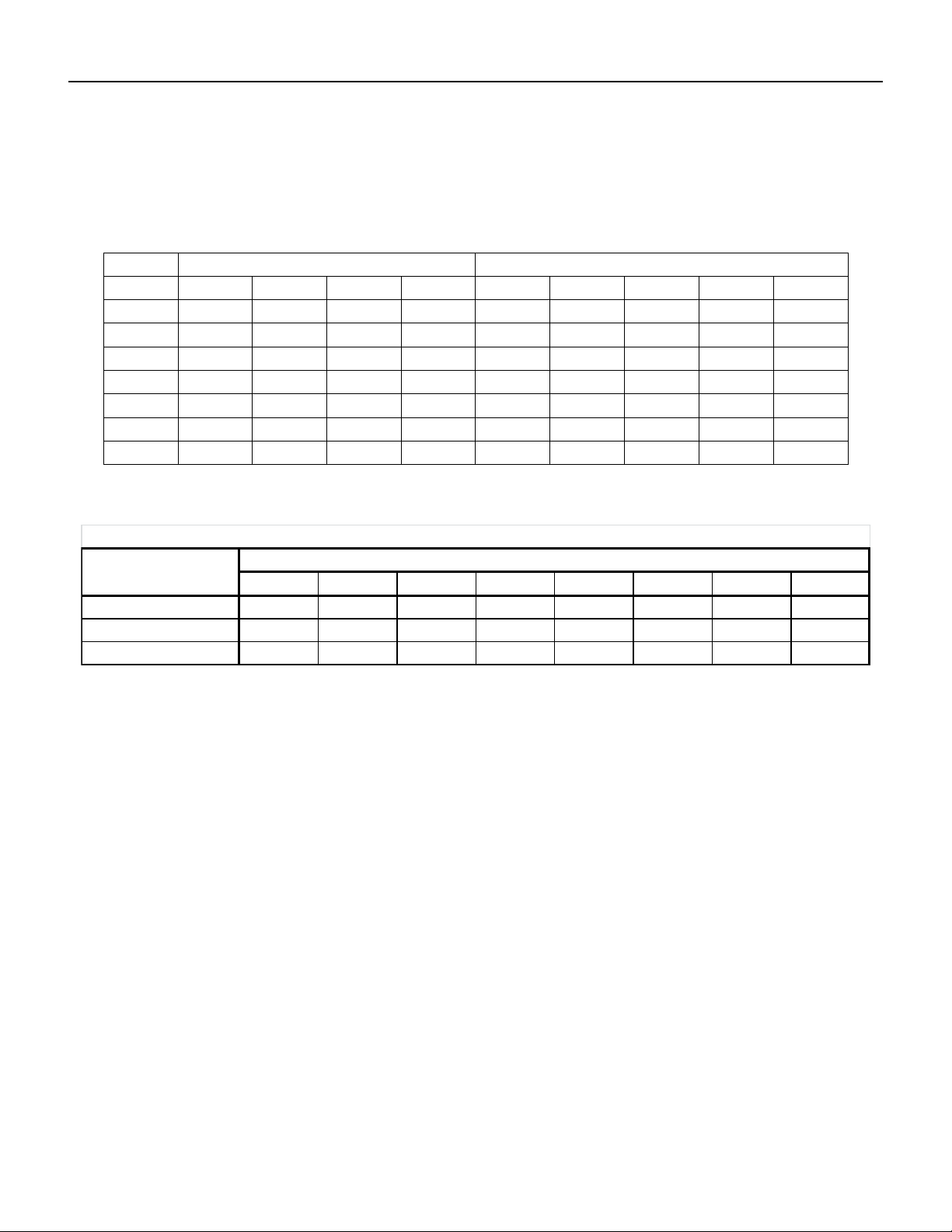
Table I indicates the maximum equivalent length of the various sizes of vent and combustion air for each
furnace model. Equivalent length equals the total length of straight pipe, plus the values for the fittings as
shown in the Table II below.
Table I
Maximum Equivalent Feet
Vent Diameter (inches)
Combustion Air Diameter (inches)
3
4
5
6
4
5
6
7
8
XES65
150
-
-
-
100
150
-
-
-
XES100
75
150
-
-
25
125
150
-
-
XES130
50
150
-
-
25
100
150
-
-
XES160
25
150
-
-
-
50
125
150
-
XES225
-
100
150
-
-
25
100
150
-
XES255
-
50
150
-
-
-
50
150
-
XES320
-
25
125
150
-
-
25
100
150
Table II
Example: System Pipe Size = 5"
2 –90° Elbows (5") = 2 x 9 = 18 ft.
5 - 4 ft. Lengths of 5" = 20 Ft.
Total Equivalent Feet = 18 ft. + 20 ft. = 38 ft.
This manual describes two options for separated combustion systems:
Side Wall Vent
oEngA Supplied
oBy Others
Vertical Vent
COMBUSTION AIR DUCT
Each separated combustion XES heater shall be equipped with its own combustion air supply. It must not
connect to any other air intake systems.
Use single wall pipe constructed of minimum 24ga galvanized steel or a material or equal durability and
corrosion resistance. Single wall combustion air duct may be externally insulated, as required.
Each slip joint shall be secured with corrosion resistant screws or rivets, and sealed with an adhesive
silicon sealant and/or aluminum tape.
For horizontal combustion air systems longer than 5 ft (1.5m) the piping must be supported every 3 ft
(1m).
3 4 5 6 7 8 9 10
811 14 15 18 21 23 26
5 7 9 10 12 14 15 17
3 4 5 5 6 7 8 9
90°
45°
Equivalent length (feet) of vent or combustion air fittings
Fittings
Vent or Combustion Air Diameter (inches)
Tee
A XES SC MANUAL
IOM-58 12 of 30 June 14 R5
VENTING PRODUCTS OF COMBUSTION
Each heater must have its own vent system, and must not be connected to other venting systems or
chimney.
Use ‘C’ Vent. All joints must be secured with corrosion resistant screws or rivet, and sealed with sealant
and/or aluminum tape rated to 500°F (290°C).
Warning:
Do not use PVC, ABS or any other non-metallic pipe for venting.
Any run of single wall vent pipe passing through an unheated space should be insulated with insulation
rated for at least 550°F (280°C) to prevent condensing. In cases where condensing is expected, install a
Tee at the bottom of the vertical section, with a drain for condensate.
Horizontal lengths of the vent system must be installed and sloped ¼”per foot (2%) to prevent the
accumulation of condensate.
Maintain a minimum of 6” (150mm) clearance from any combustible material.
Do not install dampers or other restrictive devices in the flue vent pipe.
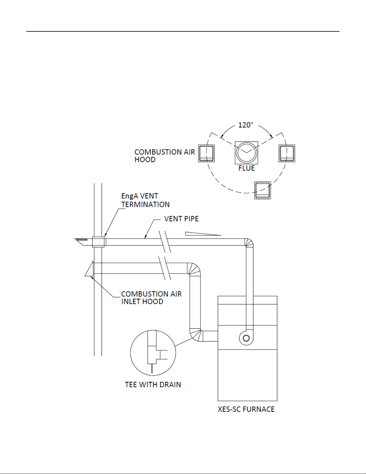
Figure 1: EngA Concentric Vent Termination
A XES SC MANUAL
IOM-58 13 of 30 June 14 R5
Figure 2: Separated Approved Vents By Others

A XES SC MANUAL
IOM-58 14 of 30 June 14 R5
Side Wall Vent –Engineered Air
Engineered Air supplied through-wall concentric vent terminations are recommended and approved for
use with XES furnace models.

A XES SC MANUAL
IOM-58 15 of 30 June 14 R5
A XES SC MANUAL
IOM-58 16 of 30 June 14 R5
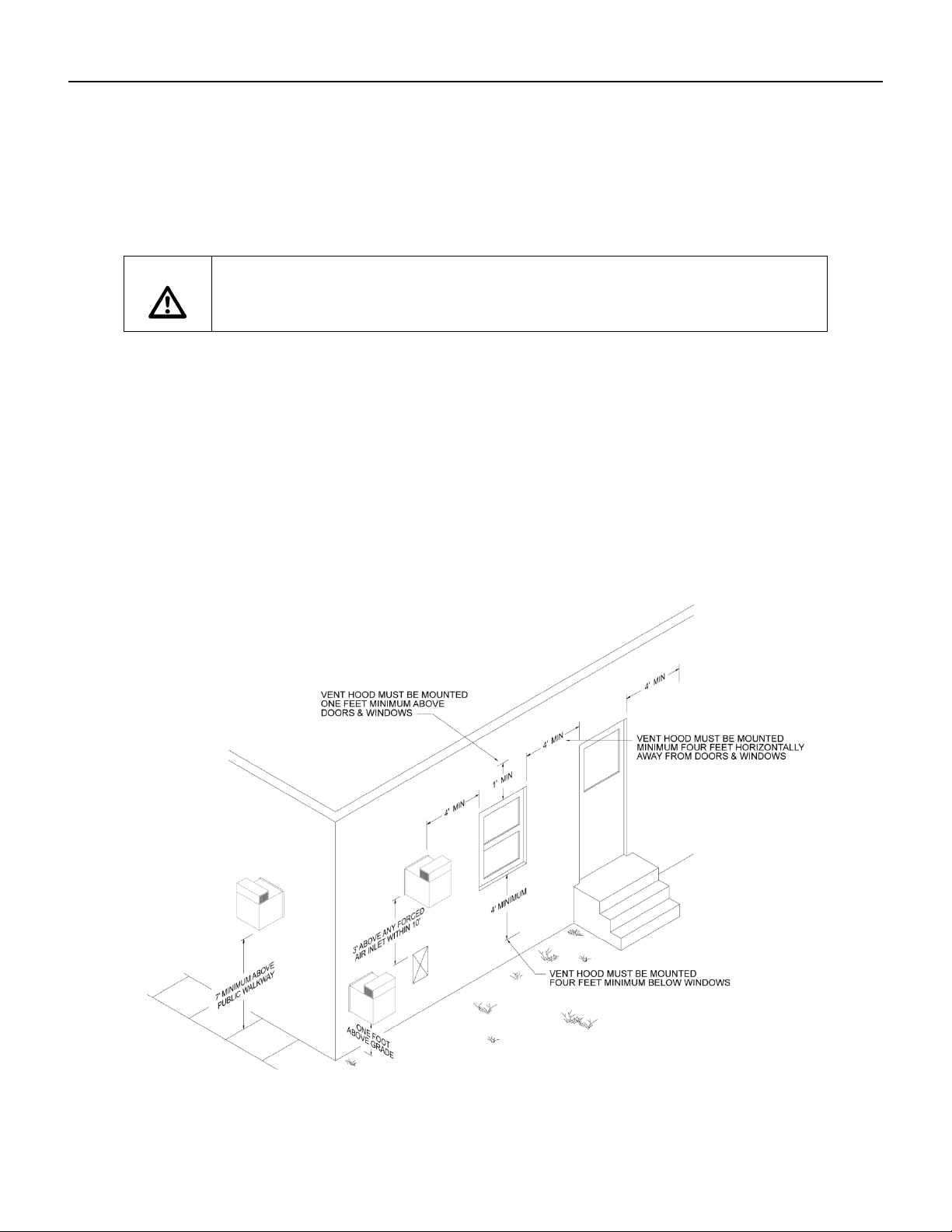
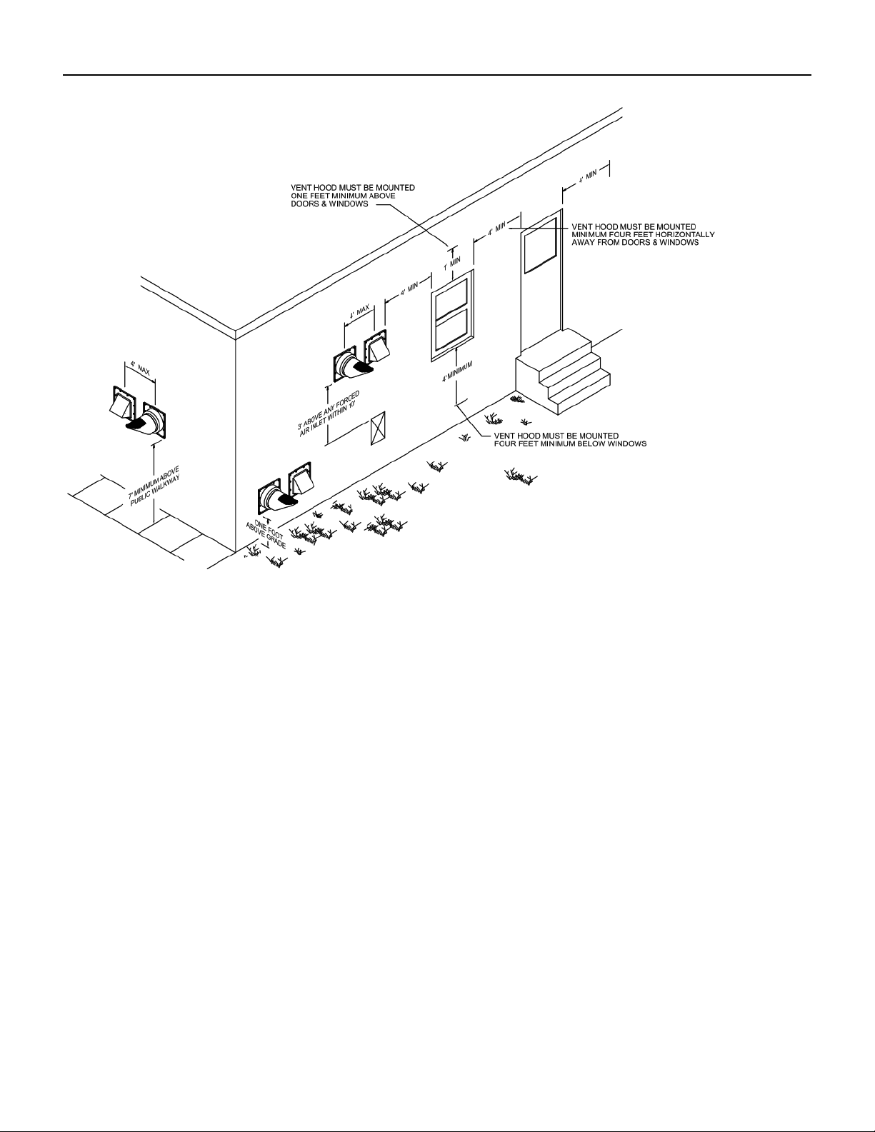
Side Wall Vent –Approved By Others
Where the Engineered Air supplied concentric flue termination cannot be used, separate approved wall
terminations may be supplied and used by the installing customer. Installation of the fresh air intake
relative to the combustion outlet must conform to the diagram shown below:
A XES SC MANUAL
IOM-58 17 of 30 June 14 R5
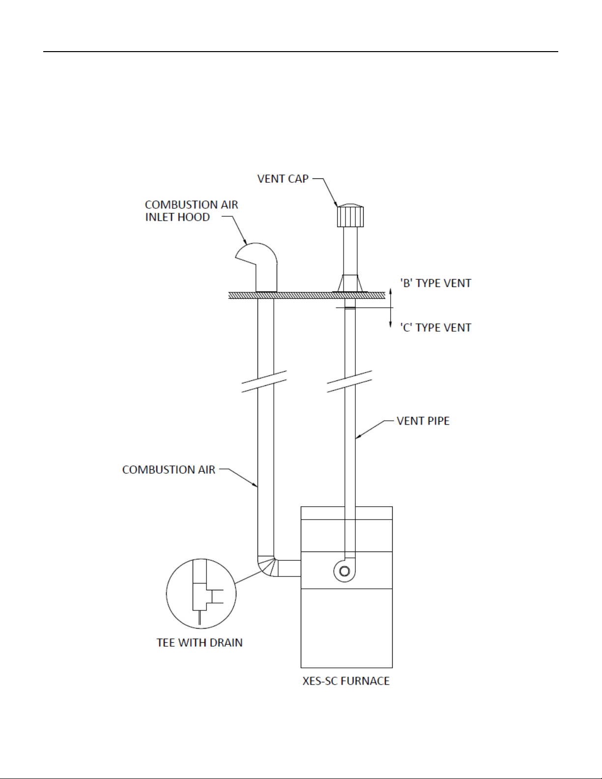
Vertical Vent
An approved vent cap (eg. Breidert), furnished by the customer, must be installed at the termination point
of the vertical vent system. The vent in this arrangement is category 1. ‘B’ Vent is acceptable. Installer
may seal joints as required.
Refer to the sketch below.

A XES SC MANUAL
IOM-58 18 of 30 June 14 R5
NATURAL GAS AND PROPANE INSTALLATION
1. Installation must be made in accordance with the requirements of the authorities having jurisdiction.
2. Check the unit rating plate and confirm fuel type, supply pressure, input rating and temperature rise.
3. Refer to the heater rating plate for determining the minimum gas supply pressure for obtaining the
maximum gas capacity for which this heater is specified.
4. Gas supply pressure higher than the unit rating plate requires an additional field supplied gas
regulator.
5. Install an approved appliance shutoff valve on the gas supply in accordance with the requirements of
the authorities having jurisdiction.
6. Gas lines shall not interfere with unit access. The gas line connection at the heater shall have an
approved drip leg with screwed cap.
7. A minimum 1/8 inch NPT plugged tapping, accessible for test gauge connection, must be installed
immediately upstream of the gas supply connection to the unit.
GAS LINE TESTING (EXTERNAL TO THE UNIT)
The appliance and its individual shutoff valve must be disconnected from the gas supply piping system
during any testing of that system at test pressures in excess of 0.5 psi (3.5 kPa).
The appliance must be isolated from the gas supply system by closing its individual shutoff valve during
any testing of that system at test pressure equal to or less than 0.5 psi (3.5 kPa).
ELECTRICAL INSTALLATION
Do not install anything that will interfere with equipment access or the rating plate.
All penetrations through the unit walls must be caulked and sealed to prevent air from entering the
unit.
The unit must be electrically grounded and all wiring must be installed in accordance with the National
Electrical Code, ANSI/NFPA 70, and/or the Canadian Electric Code CSA 22-1 and to the approval of the
authorities having jurisdiction. Field wiring diagrams, internal wiring diagrams and operating functions are
included in the control cabinet. The power requirements are indicated on the rating plate. Where field
wiring of control circuits is required, take care to size the field wiring for a maximum 10% voltage drop.
The control circuit ampacity is noted on the field wiring diagram. See the field wiring diagram for
requirements for shielded or twisted pair wire for solid state devices.
A XES SC MANUAL
IOM-58 19 of 30 June 14 R5
All wiring shall be installed according to the requirements of the authorities having jurisdiction. Field
wiring, internal wiring diagrams and unit operating functions are included in the control cabinet of the
unit. The power requirements are indicated on the rating plate.
SPLIT UNIT WIRING
All split wiring must be completed by an electrician prior to starting the equipment. A number of
different methods are used to reconnect the wiring.
Power wire: this wiring is generally not broken or spliced, and will extend from the device back to the
contactor or terminal block inside the electrical panel(s). The wire will be tagged to identify which panel it
extends to and will be numbered to the corresponding connection.
The location of the equipment split line may result in the wire being disconnected at the device it is
feeding. The wire bundle will be tagged and identified. Confirm correct rotation of 3 phase devices after
the wiring connections has been completed.
Control wire: this wire is typically broken near the split line, to be reconnected at either a enclosed
terminal block, junction box or extended to a nearby control panel. Each wire or wire bundle will be
tagged and numbered to indicate the location it is sent to.
Sensor wire shield: The drain wire from the shield must be grounded (at one end only). A ground
connection point is available for connection at the point of termination.
All loose wiring must be securely fastened to the equipment casing upon completion.
Caution:
Temporary Power Generation
The warranty will be void if the voltage being fed from any temporary generator is not
within 10% of the nominal rated nameplate voltage and voltage imbalance shall be
limited to 2%. A power monitor shall be installed by others to properly monitor power
quality and conditions.
All generator sets shall be provided with overcurrent and earth-fault protection. The
protective apparatus should be capable of interrupting, without damage, any short-
circuit current that may occur.
Warning:
No unspecified external load shall be added to the control transformer circuit(s) or to
the main power circuit(s).

A XES SC MANUAL
IOM-58 20 of 30 June 14 R5
Recommended 24V Field Wiring Size:
Copper conductors only
Circuit
Load
(Amps)
(1)
Maximum Total Length of Run
< 50 Ft
< 100 Ft
< 150 Ft
< 200 Ft
< 250 Ft
< 300 Ft
< 350 Ft
< 400 Ft
< 450 Ft
< 500 Ft
(~ 15 m)
(~ 30 m)
(~ 45 m)
(~ 60 m)
(~ 75 m)
(~ 90 m)
(~ 105 m)
(~ 120 m)
(~ 135 m)
(~ 150 m)
1
16 AWG
16 AWG
16 AWG
16 AWG
16 AWG
16 AWG
14 AWG
14 AWG
14 AWG
12 AWG
2
16 AWG
16 AWG
16 AWG
14 AWG
12 AWG
12 AWG
12 AWG
10 AWG
10 AWG
10 AWG
3
16 AWG
16 AWG
14 AWG
12 AWG
12 AWG
10 AWG
10 AWG
10 AWG
4
16 AWG
14 AWG
12 AWG
10 AWG
10 AWG
10 AWG
5
16 AWG
12 AWG
12 AWG
10 AWG
6
16 AWG
12 AWG
10 AWG
10 AWG
7
14 AWG
12 AWG
10 AWG
8
14 AWG
10 AWG
10 AWG
9
14 AWG
10 AWG
10
12 AWG
10 AWG
11
12 AWG
10 AWG
12
12 AWG
10 AWG
13
12 AWG
14
12 AWG
15
12 AWG
Notes:
1) The field wiring load depends on the actual load on a particular control circuit the field wiring is
connected to. Refer to the internal wiring diagram of the unit.
2) The table above is based on a maximum 10% voltage drop on a 24V control circuit. Wire size was
calculated using the following formula:
CM = (25 x I x L ) / V
Where CM is circular mils of conductor for a constant load of Iamps, wire length L in feet from the
unit to the field device and back, and voltage drop V.
When connecting to a three phase power supply, check for the correct rotation of all motors and fans. If
the rotation is incorrect, reverse the rotation at the incoming power only. All electrical conduit outlets in
the control panel must be sealed to prevent moist building air from migrating to the control panel.
DO NOT install any devices in a manner that interfere with access to the rating plate or door opening.
Replacement wiring must be equivalent to original wire. See field wiring diagram for requirements for
shielded or twisted pair wire for solid state devices.
This manual suits for next models
7
Table of contents
Popular Heat Pump manuals by other brands


Immergas
Immergas Rapax 300 V2 Instruction and recommendation booklet

ClimaCool
ClimaCool SHC onDEMAND Series Installation operation & maintenance

Nordyne
Nordyne T5BD Series user manual

Carrier
Carrier 50ZHA024-060 Installation & service instructions
 specification")
EMI
EMI DWPH365 (WHP36-SHC36) specification

auer
auer HRC 70 32 three-phase /3 Installation and user manual