ENGINEERING PRODUCTS 50-206 User manual
ENGINEERING
PRODUCTS
CO.,
INC.
Waukesha,
Wisconsin
OWNER'S
MANUAL
for
MODEL
50-206
42"
SNOWBLOWER AUGER
ASSEMBLY
and
MODEL
50-207
HITCH
ASSEMBLY
WARNING
READ THESE SAFETY
INSTRUCTIONS
CAREFULLY
AND
FOLLOW
THEM
CLOSELY, FAILURE TO
ADHERE
TO
THESE RULES COULD RESULT IN LOSS
OF
VEHICLE CONTROL. PERSONAL
INJURY
TO
YOURSElF.
BYSTANDERS, PROPERTY
DAMAGE
OR
DAMAGE
TO THE EQUIPMENT.
SAFETY RULES
1.
Read and
follow
operating and service
Instructions
carefully.
Be
thoroughly
familiar
with
all
controls
and
their
proper use.
2.
Never
allow
children
to operate
this
machine.
Do
not
permit
adults
to operate
equipment
without
proper
instruction.
3. Do
not
carry passengers.
4. Keep
the
area clear
of
all people not uSing
the
equipment,
children
and pets in
particular.
5.
Never
direct
discharge
toward
bystanders or
allow
anyone
near
the
vehicle
during
operation.
6. Be
sure
the
tractor is in good
working
condition, all
safety
devices and shields are
In
place and
working,
and
the
equipment
has
been
properly
adjusted.
7.
Never
attempt
to make any
adjustments
while
machine
is
running.
8.
Inspect
area to
be
cleared
for
debrIS,
doormats,
sleds,
boards,
wire,
etc.
9Be
sure
all
equipment
and
clutches
are in a
neutral
position
before
starting
engine.
10.
Wear
adequate
winter
clothing.
Wear
footwear
that
will
Improve
footing
on slippery surfaces.
11.
Handle
gasoline
with
care,
it's
highly
flammable.
12. Do
not
run
engine
in an enclosedarea-
exhaust
fumes
are
deadly.
13.
Adjust
skid shoes to
clear
gravel or
crushed
rock surfaces.
14.
Disengage
power
equipment
and
turn
off
engine
before
leaving
drlver's
position.
15.
Disengage
PTO,
turn
off
engine, and remove key before
attempting
to remove any clog.
16. Take all possible
precautions
before leaving
tractor
unattended.
Disengage
PTO,
lower
snow
blower,
turn
off
engine, and set
parking
brake. Remove key
from
ignition.
17.
After
striking
a
foreign
object, stop
the
snow
blower,
turn
off
the
engine
and
carefully
Inspect for damage.
18.
Should
the
tractor
start
to
vibrate
abnormally,
stop
the
snow
blower,
turn
off
the
engine,
and
determine
the
cause
immediately.
Vibration
is a
sign
of trouble.
19.
Always
clear
snow
up
and
down
the
face
of
aslope,
never
across
the
face of aslope. Use
extreme
caution
when
changing
directions
on aslope. Do
not
attempt
to clear
steep slopes.
98-7128
20. Disengage PTO, raise
snow
blower
before
transporting.
21. Never operate
the
snow
blower
when
visibility
or
lighting
is
poor.
OPERATING
INSTRUCTIONS
Read and
understand
the
safety
rules
and
assembly
instructions.
2. For best
snow
removal
results,
the
tractor
should
be placed
in
first
gear
with
the
engine
RPM
at
3/4
to
full
speed.
3.
Determine
the
best
snow
removal
pattern. Consider
the
size, shape, and
terrain
to be cleared
and
the
obstructions
in
the
area.
4. Drive
forward
and back.
The
long
direction
is
usually
the
best to
minimize
turning.
5.
Whenever
possible, begin
snow
removal on
the
upwind
side of
the
driveway
or
sidewalk
so
it
is
not
necessary to
blow
snow
over an already cleared area.
6.
The
Deflector
should
be
rotated to
discharge
the
snow
downwind,
not
into
it.
Always
adjust
the
Deflector
so
that
you
are
well
out
of
the
path
of
the
snow
stream.
7. Deposit
the
snow
beyond
the
area to be cleared
if
possible.
8. For
light
to
medium
snow
depths,
the
snow
blower
may
be
used
with
minimum
auger overlap
from
your
previous
path.
With
deep and very heavy
snow
conditions,
the
amount
of
overlap
should
be increased so
not
to force more
snow
into
the
unit
than
it
will
easily
handle
without
clogging.
9.
Should
the
snow
blower
become
clogged, disengage
the
PTO,
turn
off
the
engine
and
remove
the
key.
Get
off
the
tractor
and
dislodge
the
clog.
Return
to
the
tractor
and
proceed to
clear
the
snow.
10. The
snow
blower
should
be transported in araised
position
with
the
PTO
disengaged.
By
following
these
instructions,
you
should
have asafe and
effective
piece
of
equipment.
lM-9/82

ASSEMBLY
INSTRUCTIONS
PURPOSE:
This
Snowblower
is
manufactured
by
Engineering
Products
Co., Inc.
and
the
Haban
Manufacturing
Co.,
for
use on
Power
King Tractors.
It
is
intended
for use in the
removal
of
snow
from
sidewalks,
driveways,
and
other
moderately
large areas in a
safe and
effective
manner.
Strict
adherence
to the assembly,
safety,
and
operating
instructions
will
ensure
that
the
unit
will
have along and safe life.
ASSEMBLY:
The
Auger
Assembly
and
Chute
Deflector
are
contained
in
one
carton,
while
the
Hitch
and
Lift
Link
Assemblies
are in
another.
Be
sure
you have both cartons.
1.
Remove
the
AUGER ASSEMBLY,
Chute
DEFLECTOR (Item
60),
and
Chute
Direction
Control
ROD (Items
79,80,81
and
82)
from
the
first
carton. To
attach
the
Deflector
to
the
Auger
Assembly, loosen
the
four
(4) SCREWS (Item 76)
at
the
base of
the
Deflector, apply a
small
amount
of
grease
to
the
inside
of
the
Deflector
Base, and place it on
the
Auger
Assembly.
Tighten
the
four
Screws
previously
loosened.
2.
Attach
the
ends
of
the
Deflector
Control CABLE (Item
B)
to
the
opposite side (left
with
Snowblower
facing
forward)
of
the
Deflector
by
removing
Cable BOLT (Item 63)
and
WASHER (Item 62). Place both cable loops over the
weld
nut
and
replace the
bolt
and
washer.
3. Loosen
the
six Item
"C"
SCREWS
on
the
bottom
and sides
of
the
Auger
Assembly
Channel.
Also
loosen
two
Item
"B"
SCREWS on
either
side of
the
Channel. From a
position
behind
the
Auger
Assembly, slide
the
Hitch
Assembly
into
the
Channel,
making
sure
the
EYEBOLTS (Item 57)
with
one
NUT (Item 59) on
the
Channel
Side of each, are in
the
holes
in
the
Hitch
Adjusting
Blocks on
the
Hitch
Frame. Place
second NUT (Item 59) on Eyebolt
outside
of
Hitch
Adjustment
Blocks.
NOTE: Due to
manufacturmg
variation
on
the
widlh
of
the
Auger
Assembly
Channel, it
may
be necessary
on some
units
to
adjust
the
distancebelweenthe
two
Hitch
bars
that
enter
the
Auger
Assembly
Channel
In
order
to get a
sliding
fit. This can be
accomplished
by
carefully
bending
the bars.
This
will
not
affect
the
performance
of
the
unit.
Patience and care in
this
matter
will
make later
belt
adjustment
much
easier.
4. Remove the Channel COVER (Item 83). Place the shorter,
driven
BELT (Item
130)
around
the
Auger
Assembly
SHEAVE (Item
47)
and
the
lower
groove
of
the
three-groove
SHEAVE (Item
102)
at
the
rear of the
Hitch
Assembly
(see
Figure
4).
By loosening
and/or
tightening
the
Nuts
on
the
Eyebolts,
position
the
Hitch
Assembly
so
that
Belt
tension
is
properly
adjusted. Pull up on the
spring
loaded Idler
Arm
and place the belt
under
the
Idler PULLEY (Item 125). Tool
tighten
the
Screws
on sides
and
bottom
of
Auger
Assembly
Channel, and
the
Nuts
on
the
Eyebolts.
5.
With
the
Hitchl
Auger
Assembly
in a
position
under
the
tractor,
Idtthe
rear
of
the
Hitch
into
the
Rear
Hitch
Blocks
on
the
frame
of
the
tractor. Raise the
front
of
the
assembly so
that
the
front
crossbar
fits
into
the Front
Hitch
Blocks on
the
frame
of the tractor. Secure
with
Safety
LATCHES {Item
114) by
Inserting
aBlank
BOLT(ltem
116)throughthe
latch
and sma
II
upper hole in Front
Hitch
Block and
retaining
with
a
Quick
Change
KEY
(Item 113).
6.
Relieve
tension
on
driven
BELT (Item
130)
by
removing
it
from
under
Idler PULLEY {Item 125).
Allow
it
to
temporarily
drop off
of
lower
groove
of
the
three-groove
SHEAVE (Item
1021.
Disconnect
the
safety
chain
and
electrical
wire
harness
from
the
Electromagnetic
Clutch
at
the
front
of
the
tractor
engine.
Loop the longer,
Drive
BELT (Item 129) over
the
rearmost
belt
groove of
the
Electromagnetic
CIU1Ch
Pulley (except the 16 hp model
where
the
front
belt
groove
should
be
used). Thread
the
Drive
Belt
under
the
right
Idler
PULLEY (Item
119)
and
around
the
top
of
the
three-groove
SHEAVE.
Lift
up on
the
spring loaded
lefl
Idler
Arm
and
place
the
belt
under
the
left
Idler PULLEY (Item
119)
and
release arm.
This
will
a
utomatically
apply
proper
tensIOn to
Drive Belt. Replace
driven
Belt in
lower
groove of
three-
groove Sheave
as
provided in paragraph 4.
7. For
Model
1612
and all
other
tractors
with
serial
numbers
before
52589,
place
the
tractor
lift
in
such
a
position
that
the
bottom
of
lift
arm
is
as
far
forward
as possible.
Attach
the
Lift
Link
to
the
Lift
Arm
on the
right
side
of
the
Hilch
Assembly
using
the
Blank BOLT (Item 135),
1"
SPRING
(Item 136), WASHER (Item lOB) and a
Quick
Change KEY
(Item 145). Referring to
the
Universal
Lift
Link
diagram
(Figure 6). use positions Cand E
for
model
1612,
and
positions
Cand 0for
other
tractors.
8. For
tractors
other
than
the
Model
1612
and
with
serial
numbers
after
52589,
attach
the
Lifl
Li nkROD (Item
139)
to
the
Lift
Arm
with
aSCREW (Item
138)
and NUT (Item 110).
Connect the
other
end of
the
Rod
to
the
hole avai'lable in the
Rear
Lift
Link
Rod
just
in
front
of
where
it is
attached
to
the
Lift
Assembly
Arm
(as
shown
In
Tractor
Owner's
Manual).
using
the
SCREW (Item
140)
and
aNUT (Item 110).
9.
Mount
the
Chute
Control Rod BRACKET (Item
132)
to the
right
side
of
the
flywheel
housing
using
two
SCREWS (Item
131).
two
lock WASHERS (Item 142) and
two
flat
WASHERS (Item 143).
Insert
upper
section
of
ROD (Item 79)
through
the
Bracket.
Attach
the
lower
section
of
the
ROD
(Item 82) to EYEBOLT (Item 9) on
the
Auger
Assembly
and
slide
the
two
sections
of
the
Rod together.
Install
Quick
Change
KEY
(Item 81) in hole in
upper
section
below
Bracket.
10.
Adjust
the
height
of
the Skid SHOES (Item
2)
by
loosening
the
two
Screws
holding
the
Shoes
tothe
Auger
Assembly. If
the
Snowblower
IS
to be used on a
smoolh
surface, such as
concrete
or
asphalt, the
Shoes
should
be adjusted so
that
lhe
Scraper Blade is resting flat on
the
surface. If
the
intended
use is
on
agravel
or
loose
material
surface,
the
Shoes
should
be adjusted
to
allow
for a
1"
clearance
between
the
Blade and
the
surface.
To
do this,
lift
the
Snowblower
and place a
1"
thick
board
under
the
Scraper
Blade.
Lower
the
Snowblower
and
adjuslthe
Skid Shoes so
that
they
are resting on the surface.
11. Check
the
adjustment
of
the
Auger
Drive CHAIN (Item 34). If
correct,
the
chain
will
have a
slight
amount
of slack In It. In
the
event
the
Chain is not
properly
adjusted, loosen the
NUTS (Item 50) on
the
back of the
Auger
Assembly.
By
moving
these
Nuts
In
orout
you
will
be
moving
the
jackshaft
and
adjustIng
the
Drive Chain.
When
the Chain is
properly
adjusted,
tighten
the
Nuts
loosened previously.
NOTE.
If
there
was
an excessive
amount
of
adj
ustment
reqUired, go back to step 4and
readjust
the
belt
tension.

---\
\\
E.
E \ I
\\\
~~
\ I I
89~
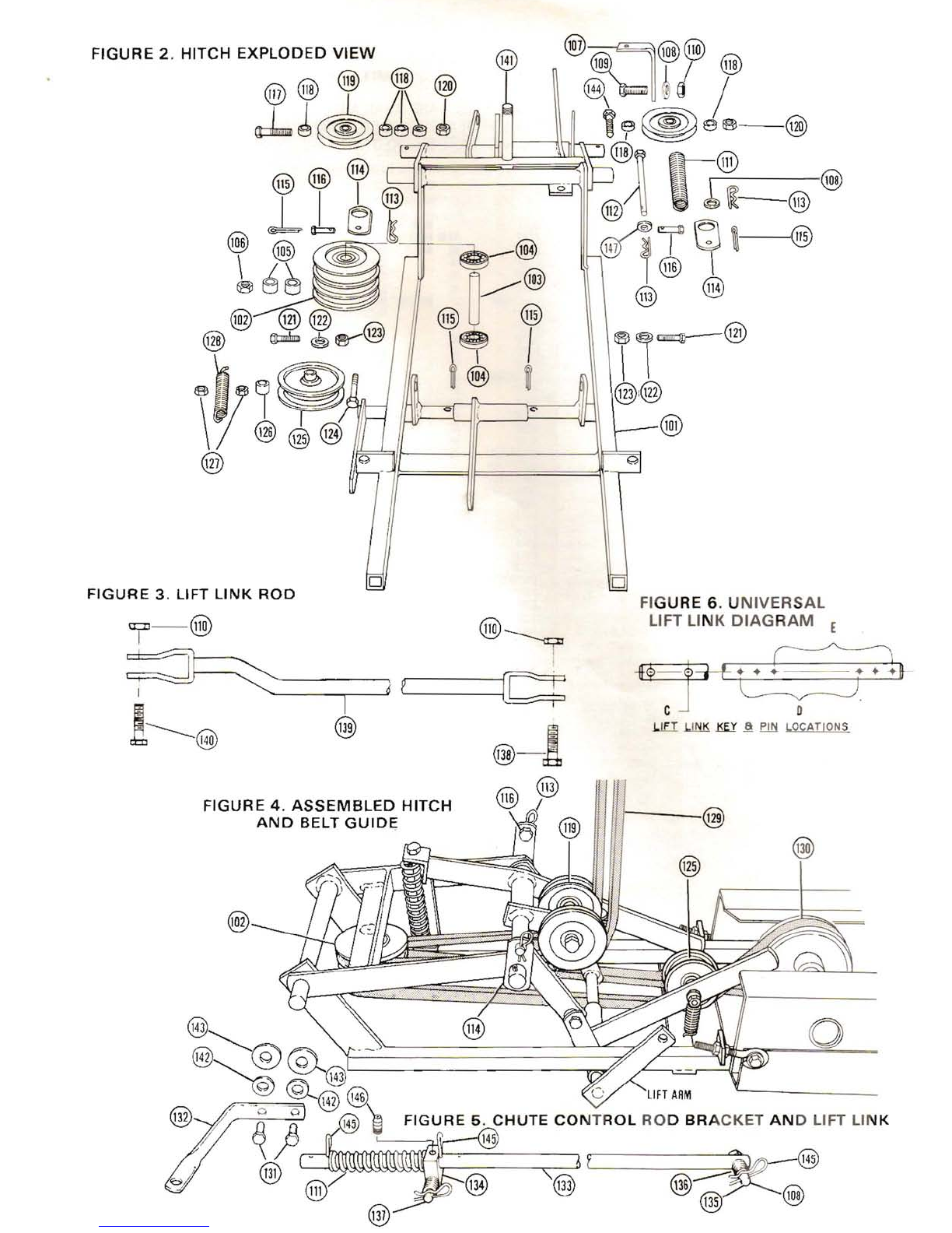
FIGURE 6.
UNIVERSAL
LIFT LINK
DIAGRAM
E
~
~~i'+
LIFT
LINK
KEl'
~
.Em
LOCATIONS
o
@-!
,G\@
~I
@
FIGURE
4.
ASSEMBLED
HITCH
AND
BELT
GUIDI;
@~
0
@)@@.'1-'---'--------------§
~
~
@
~~-
--
~--{LJI
,..
_~
~
@l
C'
LIFT
ARM
"--------
@)f/
~O
flO
@)
~
FIGURE 5.
CHUTE
CONTROL
ROD
BRACKET
AND
LIFT LINK
?
~
"I
@
~i
,@}
1
@------~®
\3'
~
@
~
'ill)
FIGURE
3. LIFT LINK ROO
i-@
@~
~~-
-----..,-f=J----;
p'-----~ti
!-----@
@

FIGURE
1,
2,
3,
4,
5
42"
SNOW
BLOWER
AND
HITCH
PARTS LISTS
NOTE:
·ONLY
THOSE
PARTS
WHICH
HAVE
"NEW
PART
NO."
ARE
AVAILABLE
FROM
ENGINEERING
PRODUCTS.
ORDER
REPLACEMENT
PARTS
DIRECT
FROM
HABAN
MANUFACTURING
CO.,
2100
NORTHWESTERN
AVE,
RACINE,
WISCONSIN
53404.
PHONE
NO.
(414)
637-8388
FOR
ANY
PART
MARKED
WITH
AN
ASTERISK
BY
THE
OLD
PART
NUMBER.
PARTS LIST
AUGER ASSEMBLY FIGURE 1
HITCH
FIGURE 2, 3, 4, 5
OLD
PART
NO.
.
..
4409'
.
..
4119'
..
GMl80018'
..
..
SW-4A
..
...
9713'
..
8203'
..
8204'
......
3430'
.8206'
..
10913'
..
GM446363'
...
10915'
........
.....
.6643'
...
7090'
...
GM271178'
DESCRIPTION
WELDMENT
....
..
Hitch
SHEAVE..
...3
Groove
SPACER
1"
OD
x3/4"
ID
x
1·
tl8"lg
BEARING
Ball
SPACER
rx3/4" x1/2"
NUT......
..3/4
NF.
Hex
lock
BRACKET.
..... .
Lower
Ang
Ie
WASHER.
.
..
7/16"
SAE
Flat
SCREW..
.7/16"
NF
x
1-1/4"
HHC
NUT.
.... .
..
7/16".
Hex
lock
SPRING.
.. .
..
Compression
6"
BOLT.... .
7/16"
Blank
x
7"
Ig.
KEY.
.... . .
Small,
Quick
change
LATCH
.
Hitch
PIN
....
.
..
Cotter
BOLT...
.318"
Blank
x
1·1/2"
Ig.
SCREW.
.
...
5/8"
NF
x2·3/4"
HHC
SPACER.
.
..
7/8" x5/8" x
3/8"
PULLEY
..
Idler,
left
and
right
NUT.
.. .5/8"
NF
Hex
lock
SCREW.
.. . 1/2"
NF
x
1-1/2"
HHC
WASHER
1/2"
Std.
Flat
NUT.... .1/2"
NF.
Hex
lock
SCREW
3/8"
NF
x
2-1/2"
HHC
PULLEY
. ..Idler
SPACER
518"
00
x
9116"
Ig.
NUT.
.... .
318'
NF.
Hex
lock
SPRING.
. .
EXlension
BELT.
... .
..
Drive,
72"
BEL
T...... .
..
Connecting
68"
SCREW..
..,
.3/8"
NF
x
718"
HHC
BRACKET
Chute
Control
Rod
LINK
Lift.
Universal
front
46"
BRACKET
Lift
Link
BOLT
7/16"
Blank
x
2"
SPRING
Compression
1"
BOLT... .. .7/16"
Blank
x
3"
SCREW... .7/16"
NF
x
2"
ROD...
..
.Lift
SCREW..
.
...
7/16"
NF
x1·1/4"
SCREW.
.3/4"
NF
x
5"
WASHER
.3/8"
lock
WASHER
....
3/8"
std.
flat
SCREW
.5/8"
NF
x
2"
KEY.
.... ..
Quick
change.
large
FITTING
.Grease.
1/4"
NF.
short
DESCRIPTION
SPACER
.
UT.
Hex
lock
.25
-
20.
..
....
.
....
BOL
T,
Hex
head
.25
-
20
x
.62
..
WASHER.
Locking
25
.
DECAL.
Caution
.
ROD.
Crank
......................•...
GRIP,
Crank
rod
. .
PIN,
Hair
colter. ..... .
.......•...
,.
ASSY.
Extension.
crank
rod. ...•..
..
.
...
COVER,
Rear
channel. .. .. . .... ...
..
..
WASHER.
Flat
.37
..
STRAP,
Cover
mounting
.
BLADE,
Scraper
.
BOL
T,
Carriage
.25
.
20
x
.62
.
ASSY,
Nut
and
lockwasher
.25
.
20
hex
.
RETAINER
BELT
NEW
ITEM
PART
NO. NO.
74
75
76
77
84-3040
78
79
80
81
82
83
84
85
86
87
88
89
50-0132
ITEM
PIN
101
50-2900
102
50-7100
103
83-D044
104
80-0029
105
83-0021
106
84-0175
107
50-0506
108
84-3060
109
84-2171
110
84-0120
111
83-D124
112
84-1090
113
84-4032
114
51-4705
115
84-4020
116
84-1101
117
84-1043
118
83-1024
119
86-0003
120
84-0140
121
84-1171
122
84-3~1
123
84-0130
124
84-2151
125
86-0~1
126
83·0127
127
84-0110
128
83-D125
129
81-0074
130
81-0070
131
84-2110
132
50-0505
133
50-4701
134
15-0505
135
84·1111
136
83-0024
137
84·1121
138
84-2180
139
50-2503
140
84-2171
141
84-2390
142
84-3020
143
84-3037
144
84-1042
145
84-4031
146
03-2102
OLD
PART
DESCRIPTION
NO.
HOUSING.
Header.
. ... ... ... . . ... .. .. .. ... .
..
.
8580'
SHOE.
Skid. .. .. .. ... ....
..
..
..
.3045'
BOLT.
Carnage
.31
-
18
x
.75
.. .. ... ..
....
.. .
7953'
ASSY.
Nut
and
lac
washer
.31
.
18
'lex
. .
GM271184'
ASSY.
Stack
drive...........
.
.9363'
SHROUD,
Stack
drive. ....... .
9030'
ASSY.
Tube
and
bracket.....
.
9032'
ASSY.
Cable,
tube.
and
sleeve.
.
8233'
EyEBOLT....
..
..3955'
WASHER.
Flat
.37
SAE
' ,. ...
GM120388'
WASHER.
Spring..................
...
4772'
NUT.
Eyebolt
.37·16..
.
.SN-4
U-BOLT,
(Level
wind)... .
8236'
STRAP.
Friction.........
.
.8299'
NUT.
Hex
lock
.25·20...
.
4119'
BOLT.
Carriage
.37
-
16
x
.75
.... .. . .
GM126227'
ASSY,
Nut
and
lockwasher
.37
-
16
hex.
.
GM271190'
BOL
T,
Carnage
.37
-
16
x
1.00
...........
...
.. ..
...
.
..
.
..
GM
120915'
ASSY.
Nut
and
lockwasher
.37
-
16
hex
GM271190'
WASHER.
Flat
.41
4506'
ASSY,
Auger....
..
.
..
8176'
SHAFT.
Auger.........
..
8181'
BEARING.
Auger.......
.
5474'
WASHER.
Flat
1.09..
..
.4143'
FLANGE.
Bearing.. ..
..
5473'
BOL
1,
Hex
head
.31
.
18
x
75.
...
.
..
GM18oo77'
WASHER,
Lock
.31
•
SW-l
SPROCKET.
Auger
35
tooth........
..
8287'
PLATE.
Auger
mountlllg
..
8185'
BOLT,
Hex
head
.31
-
18
x
.62
.
..
GM18007S'
BOLT,
Hex
head
.50
-
13
x
1.25
.. ,
GMl80175'
WASHER.
Lock
.50
.. ... ..... . .
SW-l1
CHAIN.
Auger
drive.
70
IlIlks
..
...
3028'
LINK,
Connec1or
(Used
for
repair
only)
..
..
8456'
GUARD.
Chain. .
3036'
SCREW,
Hex
washer
head
.25·20 x
.50
self
tapping. .
GM9414012'
ASSY.
Jackshaft
hOUSing
With
bearings.. .
8393'
BEARING,
Needle
8689'
FITTING.
Grease
.25
-
28
straight ,.... .
..
.
F·2
ASSY.
Jackshaft
and
sprocket
. ..
..
....• . .. .
8396'
BOLT,
Hex
head
.37
-16 x.75
GM180120'
WASHER,
Flat
.43......
.. .. ..
GM
120388
WASHER.
Lock
.37...
..
GM120382
WASHER.
Flat
.75.......
.
SW-7
KEY.
Drive
pulley
.18
square
x
1.00
. .
3259'
ASSY,
Pulley
and
hub...
.
3035'
SCREW,
Set-square
head
cap
point
.31
.
18
x
50....
.
..
GM142671'
WASHER.
Flat
.50......
..
SW-6A
NUT.
Hex
.50
-
13
. ... .
SN-5
PLATE.
Relllforcement
. .. .. .. ... .• ... .
..
8329'
PLUG.
Bulton
...... ..... ... .
..
7677'
BRACKET
ASSY.
Channel. .... .
..
....
.
..
.
...
...
7577'
BOLT.
Hex
head
.37
-
16
xl
00
GMl80122'
WASHER,
Lock
.37
...
..
..
..
..
.. .. ..
.. .
SW-2
BOLT.
Hex
head
.37
·16
x 2
.......
..
.GMl80130
EYEBOLT
..
... .. .......
.3955'
TRUNNION................
..
3700'
NUT.
Hex
.37
-
16
.
GM120377'
ASSY.
Deflector
and
elbow.
.... ..
..
..
.. .
8584'
ASSY.
Elbow
and
PiVOt.
.
8585'
WASHER.
Cable.
.3903'
BOL
T.
Cable
25 -
20
x.50..
..
... ...
5B-l
B
ASSY.
Deflector
and
decal. ..
..
. .
...
9737'
DECAL.
Warning.............
..
..
9663'
MOLDING,
Deflector. .......... .
.6558'
BOLT,
Carnage
.31
-
18
x100. .. ...
GM126358'
WASHER.
Lock
int/ext
tooth
.37
.
GM178566'
WASHER.
Flat
.37..
.....
.. ..
SW-2
STRAP.
Locking
.8198'
NUT.
Hex
locking
.31
-18. .."
SN-l0A
HOOK.
Lift
spring
...
3076'
BOL
T,
Hex
head
.25
-
20
x
1.25
. ...
SS-35A
NEW
ITEM
PART
NO. NO.
2
3
4
5
6
7
8
9
10
11
12
84-0040
13
14
15
16
17
18
19
20
21
22
23
24
25
26
27
84-3010
28
30
31
32
33
84-3110
34
35
36
37
38
39
40
03-2102
41
42
43
84-3060
44
84-3020
45
84-3070
46
47
48
49
84-3061
50
84-0050
51
52
53
54
55
84-3020
56
84-2102
57
58
59
60
61
62
63
84-1012
64
65
66
67
68
69
84-3020
70
71
84-0101
72
73
84-2350
MAINTENANCE
INSTRUCTIONS
1.
The
snow
blower
has a
grease
fitting
located
on
the
Auger
Jackshaft
(Item
40,
Figure
1)
which
should
be greased every
10
hours
or use
with
a
multi-purpose
grease.
2. Once a
year
or
more
often
depending
on
usage,
the
chain
tension
should
be checked
and
adjusted
if
required
and
lubricated.
3.
Drive
belt
tension
should
be checked
periodically
and
adjusted
when
needed. The
belts
should
be checked
for
wear
also
at
this
time.
Replace
worn
and frayed belts.
4.
To
store
the
snow
blower
for
the
off-season,
remove
the
snow
blower
from
the
tractor.
Use
water
and
a
brush
to
thoroughly
clean
the
Auger
Assembly
and
Hitch.
Paint
any
chips
or
worn
areas,
and
put
a
light
coat
of
oil
on
the
unit
to
prevent
rust.
Lubricate
all
moving
parts,
bearings,
sheaves,
cross shafts. etc. Cover
with
atarp
or
plastic
and store
in
a
dry place.
This manual suits for next models
1
Table of contents


