Englander 25-CAB80 User manual

46311A
2023-01-16
CAUTION
PLEASE READ THIS ENTIRE MANUAL BEFORE INSTALLATION AND USE OF THIS PELLET FUEL-BURNING
APPLIANCE. KEEP CHILDREN, FURNITURE, AND ALL COMBUSTIBLES AWAY FROM ANY HEATING APPLIANCE.
SAFETY NOTICE
FAILURE TO FOLLOW THESE INSTRUCTIONS CAN RESULT IN PROPERTY DAMAGE, BODILY INJURY OR EVEN
DEATH. FOR YOUR SAFETY AND PROTECTION, FOLLOW THE INSTALLATION INSTRUCTIONS OUTLINED IN
THIS MANUAL. CONTACT YOUR LOCAL BUILDING OR FIRE OFFICIALS ABOUT RESTRICTIONS AND
INSTALLATION INSPECTION REQUIREMENTS (INCLUDING PERMITS) IN YOUR AREA.
Manufactured By: Stove Builder International inc., 250, rue de Copenhague, St-Augustin-de-
Desmaures (Québec) Canada, G3A 2H3
SAVE THESE INSTRUCTIONS
INSTALLATION & OPERATION
MANUAL
25-CAB80
55-SHPCAB80
55-TRPCAB80
25-CAB80S
55-SHPCAB80S
55-TRPCAB80S
THIS WOOD HEATER NEEDS PERIODIC INSPECTION AND REPAIR FOR PROPER OPERATION. CONSULT THE
OWNER’S MANUAL FOR FURTHER INFORMATION. IT IS AGAINST FEDERAL REGULATIONS TO OPERATE THIS
WOOD HEATER IN A MANNER INCONSISTENT WITH THE OPERATING INSTRUCTIONS IN THE OWNER’S
MANUAL.
www.englander-stoves.com
Support: (877) 356-6663
Email: tech@sbi-
international.com

2
IMPORTANT! READ AND FOLLOW ALL INSTALLATION AND MAINTENANCE INSTRUCTIONS, INCLUDING CLEANING THE UNIT AS SPECIFIED, AND
REPLACING GASKETS ANNUALLY, AND PARTS AS NEEDED.
ENGLANDER IS NOT RESPONSIBLE FOR ANY DAMAGE OR INJURY INCURRED DUE TO NEGLECT, OR DUE TO UNSAFE INSTALLATION OR USAGE OF
THIS PRODUCT. CALL TECHNICAL SUPPORT WITH ANY QUESTIONS.
IMPORTANT: IF YOU HAVE A PROBLEM WITH THIS UNIT, DO NOT RETURN IT TO
THE DEALER. CONTACT TECHNICAL SUPPORT @ 1-877-356-6663
Tamper Warning:
This wood heater has a manufacturer-set minimum low burn rate that must not be
altered. It is against federal regulations to alter this setting or otherwise operate
this wood heater in a manner inconsistent with operating instructions in this
manual.
Mobile Home Use:
This freestanding pellet unit is approved for mobile home or doublewide
installation with the outside combustion air hook-up See the “Installation” section
of this manual for details pertaining to mobile home installations. Mobile home
installation must be in accordance with the Manufactured Home and Safety
Standard (HUD), CFR 3280, Part 24.
WARNING:
USE OF OUTSIDE COMBUSTION AIR IS MANDATORY WITH THIS UNIT.
DO NOT OPERATE WITH THE HOPPER OPEN; LID MUST BE SHUT AND TIGHTLY
LATCHED DURING OPERATION. DO NOT OVER-FIRE YOUR UNIT.
Note: Englander does not recommend using a pellet stove as your only source of
heat.
Retain for your files
Model Number
Date of Purchase
Date of Manufacture
Serial Number

3
IMPORTANT! READ AND FOLLOW ALL INSTALLATION AND MAINTENANCE INSTRUCTIONS, INCLUDING CLEANING THE UNIT AS SPECIFIED, AND
REPLACING GASKETS ANNUALLY, AND PARTS AS NEEDED.
ENGLANDER IS NOT RESPONSIBLE FOR ANY DAMAGE OR INJURY INCURRED DUE TO NEGLECT, OR DUE TO UNSAFE INSTALLATION OR USAGE OF
THIS PRODUCT. CALL TECHNICAL SUPPORT WITH ANY QUESTIONS.

4
IMPORTANT! READ AND FOLLOW ALL INSTALLATION AND MAINTENANCE INSTRUCTIONS, INCLUDING CLEANING THE UNIT AS SPECIFIED, AND
REPLACING GASKETS ANNUALLY, AND PARTS AS NEEDED.
ENGLANDER IS NOT RESPONSIBLE FOR ANY DAMAGE OR INJURY INCURRED DUE TO NEGLECT, OR DUE TO UNSAFE INSTALLATION OR USAGE OF
THIS PRODUCT. CALL TECHNICAL SUPPORT WITH ANY QUESTIONS.
Welcome!
Introduction
•Thank You ......................................... 4
Specifications
•Heating Specifications ....................... 5
•Dimensions ........................................ 5
•EPA Compliance................................. 5
Installation
•Installation Overview...................6
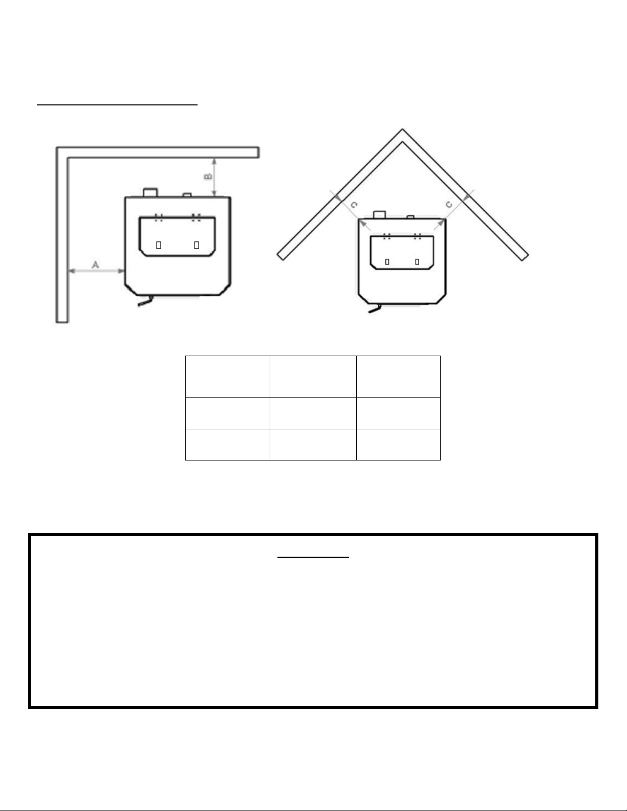
•Clearances to Combustibles.........7
•Venting Introduction................... 8
•Venting Guidelines.......................8
•Additional Venting Information....9
•Approved Venting Methods
•Through the Wall ...........10
•Through the Ceiling........11
•Existing Chimney............ 12
•Mobile Home Installation............ 13
•Vent Termination Clearances...... 14
•Outside Air Hookup..................... 15
•Floor Protection........................... 16
Daily Operation
•Control Board Types ………………… 17
•Getting Started............................ 18
•Lighting a Fire.............................. 18
•Daily Operation Notes ……………… 19
Control Board
•Top Mount Board Settings........... 21
•Error Codes (Top Mount) ............ 23
•Diagnostic Mode (Top Mount) ....29
•Side Mount Board Settings........... 31
•Side Mount Error Codes ............... 32
•Power Failure ............................... 33
Maintenance
•Daily
•Important Notes.............. 34
•Daily Ash Removal............ 34
•Cleaning the Burn Pot …...35
•Weekly
•Baffle Removal................. 36
•Monthly
•Venting Pipe Cleaning ….. 37
•Yearly
•Important Notes.............. 38
•Burn Pot ……….................. 39
•Exhaust Blower …………….. 39
•Convection Blower........... 40
•Finish ………….................... 40
•Gaskets ………………………… 40
•Basic Troubleshooting ....................... 41
Replacing Components
•Convection Blower ............................43
•Auger Motor ……….............................44
•Combustion Blower............................45
•Vacuum Switch...................................46
•Igniter.................................................48
•Gaskets...............................................49
•Glass...................................................50
•Control Board (Top Mount) ...............51
•Control Board (Side Mount)...............53
•Hopper Lid Latch ….............................55
Illustrated Parts Detail
•Exploded Parts Diagram……………………56
•Parts List……………………………………..….. 57
Warranty
•Serial Tag Sample…………………….………..59
•Warranty Details……………………………....60
•Important Notice………….…….....…………62
•Warranty Reg. Form………………………….63

46311A
2023-01-16
INTRODUCTION
Thank you for purchasing this fine product from Englander!
Englander was started, and is still owned, by a family that believes strongly in a
“Do It Yourself” spirit; that’s one reason you found this product at your favorite
“Do It Yourself” store.
We intentionally design and build our stoves so that any homeowner can maintain
their stove with basic tools, and we’re always more than happy to help you do the
job as easily and as inexpensively as possible. However, while remaining simple,
our stoves are designed to perform extremely efficiently, helping deliver more
heat from less fuel.
Please look at the extensive Help section on our website and call our Technical
Support Department at (877) 356-6663 if you need any help with your stove. We
are nearly always able to “walk you through” any installation issues, repairs,
problems or other questions that you may have.
Wishing you years of efficient, quality and “comfy” heating,
Everyone at Englander
Please Note: While information obtained from our web site and through our
Technical Support line is always free of charge, there will be a service charge
incurred with any “on-site” repairs or maintenance that we may arrange.
This manual is available for free download on the manufacturer’s web site. It is a copyrighted document and resale
is strictly prohibited. The manufacturer may update this manual occasionally and cannot be responsible for
problems including injuries or damages resulting from the use of information found in any manual from
unauthorized sources.
CAUTION: Stove is heavy.
In addition, when handling any sheet metal products, be aware that there may be sharp edges or burrs.
Although we make every effort to eliminate any sharp edges, please use caution when handling any metal parts.
Remember to disconnect (unplug) the stove from the power source and allow it to completely cool down
before performing any maintenance.

6
IMPORTANT! READ AND FOLLOW ALL INSTALLATION AND MAINTENANCE INSTRUCTIONS, INCLUDING CLEANING THE UNIT AS SPECIFIED, AND
REPLACING GASKETS ANNUALLY, AND PARTS AS NEEDED.
ENGLANDER IS NOT RESPONSIBLE FOR ANY DAMAGE OR INJURY INCURRED DUE TO NEGLECT, OR DUE TO UNSAFE INSTALLATION OR USAGE OF
THIS PRODUCT. CALL TECHNICAL SUPPORT WITH ANY QUESTIONS.
SPECIFICATIONS
Heating Specifications
•Approximate Pellet Burn Rate**……….…………1.0 to 1.8 kg/hr (2.2 to 3.8 lbs/hr)
•Maximum Burn Time**………………………………………………………………………..36 hours
•Approximate Square Footage Heated***………...………………………….up 2,000 sq. ft.
•Hopper Capacity (fuel)…………………………………….…………………………….…..80 pounds
Dimensions
EPA and Safety Compliance Specifications
•EPA Compliance Status …………………. Certified to comply with 2020 particulate emission standards
using pellet fuel.
•U.S. Test Standard: US EPA 40 CFR Part 60, Subpart 60.536
•Heat output range****……………. 11,641 BTU/h to 20,959 BTU/h (3.41kW to 6.14 kW)
•Particulate Emissions ………………………………………………………………… 1.130 grams/hr
•CO Emissions ……………………………………………………………………………. 0.029 grams/hr
•Efficiency……………………………………………………………………………………… 64.1 % (HHV)
•BTU rating ……………………………………………………………………………………. 20,511 BTU/hr
•Tested To ASTM E 1509, ASTM E2779, ASTM E2515, CSA B415.1 & ULC S627
Notes for this unit:Product may vary slightly from diagram. Clearances are the minimum for this unit
and may need to be increased in the rear to have proper vent clearances. Follow all venting manufacturer
clearances and local codes.
*- As tested per ASTM 2779
** - Heat output, burn rate and maximum burn time are heavily dependent on the type of pellets burned in the stove; as such, these numbers may vary.
*** - The maximum heating capacity of this unit can vary greatly based on climate, construction style, insulation and a myriad of other factors. Use this information
in conjunction with a BTU loss calculation for your home to determine if this unit will be sufficient for your needs.
**** - As measured per CSA B415.1-10 stack loss method.

7
IMPORTANT! READ AND FOLLOW ALL INSTALLATION AND MAINTENANCE INSTRUCTIONS, INCLUDING CLEANING THE UNIT AS SPECIFIED, AND
REPLACING GASKETS ANNUALLY, AND PARTS AS NEEDED.
ENGLANDER IS NOT RESPONSIBLE FOR ANY DAMAGE OR INJURY INCURRED DUE TO NEGLECT, OR DUE TO UNSAFE INSTALLATION OR USAGE OF
THIS PRODUCT. CALL TECHNICAL SUPPORT WITH ANY QUESTIONS.
INSTALLATION
Installation Overview
When choosing a location for your new stove, there are a multitude of factors that
should be taken into account before beginning the installation.
1. Traffic Patterns – To help prevent accidents, the stove should be placed in a location
where it is out of the way of normal travel through the home.
2. Heat Flow and Efficiency – When deciding on a location for the stove, consider the way
heat moves throughout your home. Install the stove where you need the heat;
basement installations often do not allow sufficient heat to flow to the upper floors and
a top floor installation will not allow any heat to reach the floors below. Always
consider that heat rises and will take the path of least resistance while it is still hot.
3. Exhaust Location – Outside walls are generally the best place to install a stove, since
they allow easy exhaust and intake air installation (using our Dura Vent AC-3000 Kit, AC-
33000 if Canada). If there is not a feasible way to install the stove on an outside wall,
there are methods for venting the stove up through the roof, but they tend to be more
costly because they involve the use of more pellet vent pipe and can often make outside
air installation more difficult.
4. Wall Construction – Locating the stove so that the exhaust system can pass between
studs will simplify the installation and eliminate the need to reframe any sections of the
wall to accommodate the wall thimble.
Warning
•Do not store or use gasoline or other flammable vapors and liquids in the vicinity of this or any
other appliance.
•Do Not Over fire – If any external part starts to glow, you are over firing. Reduce feed rate.
Over firing will void your warranty.
•Comply with all minimum clearances to combustibles as specified. Failure to comply may
result in a house fire.
•Tested and approved for wood pellets only. Burning any other fuel will void your warranty.
•For use with Premium grade wood pellets only.

8
IMPORTANT! READ AND FOLLOW ALL INSTALLATION AND MAINTENANCE INSTRUCTIONS, INCLUDING CLEANING THE UNIT AS SPECIFIED, AND
REPLACING GASKETS ANNUALLY, AND PARTS AS NEEDED.
ENGLANDER IS NOT RESPONSIBLE FOR ANY DAMAGE OR INJURY INCURRED DUE TO NEGLECT, OR DUE TO UNSAFE INSTALLATION OR USAGE OF
THIS PRODUCT. CALL TECHNICAL SUPPORT WITH ANY QUESTIONS.
INSTALLATION
Clearances to Combustibles
CAUTION
•Unit can be very HOT while in operation. Keep children away.
•Supervise children in the same room as this appliance.
•Alert children and adults to the hazards of high temperatures.
•Do NOT operate with protective barriers open or removed.
•Keep clothing, furniture, draperies and other combustibles away.
•Installation MUST comply with local, regional, state and national codes and regulations.
•Consult local building, fire officials or authorities having jurisdiction about restrictions, installation inspection, and
permits.
DO NOT CONNECT TO ANY AIR DISTRIBUTION DUCT OR SYSTEM
Unit to Side
Wall (A)
Unit to Rear
Wall (B)
Unit to Corner
(C)
7 in. 0 in. 5 in.
178 mm 0 mm 127 mm

9
IMPORTANT! READ AND FOLLOW ALL INSTALLATION AND MAINTENANCE INSTRUCTIONS, INCLUDING CLEANING THE UNIT AS SPECIFIED, AND
REPLACING GASKETS ANNUALLY, AND PARTS AS NEEDED.
ENGLANDER IS NOT RESPONSIBLE FOR ANY DAMAGE OR INJURY INCURRED DUE TO NEGLECT, OR DUE TO UNSAFE INSTALLATION OR USAGE OF
THIS PRODUCT. CALL TECHNICAL SUPPORT WITH ANY QUESTIONS.
INSTALLATION
Venting Introduction
This pellet stove operates on a negative draft system, which pulls combustion air through the
burn pot and pushes the exhaust air through the vent pipe and out of the building. This unit must be
installed in accordance with the following detailed descriptions of venting techniques; not installing
the stove in accordance with the details listed here can result in poor stove performance, property
damage, bodily injury or death. Englander is not responsible for any damage incurred due to a poor
or unsafe installation.
If questions arise pertaining to the safe installation of the stove, our Technical Support line
(877-356-6663) is available. Contact your local code official to be certain your installation meets local
and national fire codes and if you’re uncertain about how to safely install the stove, we strongly
recommend contacting a local NFI certified installer to perform the installation.
Venting Guidelines
•WARNING - INSTALL VENT AT CLEARANCES SPECIFIED BY THE VENT MANUFACTURER.
•ALWAYS install vent pipe in strict adherence with the instructions and clearances included with
your venting system.
•DO NOT connect this pellet stove to a chimney flue which also serves another appliance.
•DO NOT install a flue pipe damper or any other restrictive device in the exhaust venting system
of this unit.
•USE an approved wall thimble when passing through a wall and a ceiling support/fire stop
when passing through a ceiling.
•ONLY use 3.0” or 4.0” Type L or Type PL pipe approved for pellet stove venting; DO NOT use
galvanized or B-Vent pipe.
•SEAL each joint of pellet vent with high temperature silicone (Part # AC-RTV3) to prevent
smoke spillage into the home.
•AVOID excessive horizontal runs and elbows, as both will reduce the draft of the venting
system and will result in poor stove performance.
•INCLUDE as much vertical pipe as possible to prevent smoke from the unit from entering your
home in the event of a power outage.
•INSPECT your venting system often, to be certain it is clear of fly-ash and other restrictions.
•CLEAN the venting system as detailed in the maintenance section of this manual.
WARNING
•INSTALL VENT AT CLEARANCES SPECIFIED BY THE VENT MANUFACTURER.
•HOT! Do not touch! Severe burns or clothing ignition may result.
•Glass and other surfaces are hot during operation.
•Do not attempt to touch or open the front, side or back panels during operation. This could result in
severe burns or injury.

10
IMPORTANT! READ AND FOLLOW ALL INSTALLATION AND MAINTENANCE INSTRUCTIONS, INCLUDING CLEANING THE UNIT AS SPECIFIED, AND
REPLACING GASKETS ANNUALLY, AND PARTS AS NEEDED.
ENGLANDER IS NOT RESPONSIBLE FOR ANY DAMAGE OR INJURY INCURRED DUE TO NEGLECT, OR DUE TO UNSAFE INSTALLATION OR USAGE OF
THIS PRODUCT. CALL TECHNICAL SUPPORT WITH ANY QUESTIONS.
INSTALLATION
Additional Venting Information
•Do not mix and match components from different pipe manufacturers when assembling your
venting system (i.e. Do NOT use venting pipe from one manufacturer and a thimble from
another).
•We require a minimum vertical rise of 36 in. (3 ft.) of pipe to create natural draft in the system.
This helps evacuate smoke from the stove in the event of a power failure or combustion
blower failure.
•Venting systems 15.0 ft. or shorter may be composed entirely of 3.0 in. pellet pipe; to reduce
frictional losses, venting systems longer than 15.0 ft. should be composed of 4.0 in. pellet pipe.
•Do not terminate the venting system directly beneath any combustible structure such as a
porch or deck.
•Follow NFPA 211 rules listed below for venting system termination location relative to
windows and other openings in the dwelling.
oNFPA 211 (2006 ed.) Section 10.4 Termination: 10.4.5
(1) The exit terminal of a mechanical draft system other than direct vent appliances
(sealed combustion system appliances) shall be located in accordance with the
following:
(a) Not less than 3 ft. (.91 m) above any forced air inlet located within 10 ft.
(3.0m).
(b) Not less than 4 ft. (1.2 m) below, 4 ft. (1.2 m) horizontally from or 1 ft. (305
mm) above any door, window or gravity air inlet into any building.
(c) Not less than 2 ft. (0.61 m) from an adjacent building and not less than 7 ft.
(2.1 m) above grade when located adjacent to public walkways.
•Distance between the termination opening and grade should be a minimum of 2 ft. (24 in.)
contingent on the grade surface below the termination. When determining the termination
height above grade, consider snow drift lines and combustibles such as grass or leaf
accumulation. In areas where significant snowfall is possible, the termination height must be
sufficiently high to keep the termination free of snow accumulation.
•Do not use makeshift compromises during installation or install any component of the unit or
venting system in such a manner that could result in a hazardous installation.
•A chimney connector shall not pass through an attic or roof space, closet or similar concealed
space, or a floor, or ceiling.
•Where passage through a wall or partition of combustible material is desired, the installation
shall conform to CAN/CSA-B365.
WARNING:
Venting system surfaces get HOT, and can cause burns if touched.
Noncombustible shielding or guards may be required.

11
IMPORTANT! READ AND FOLLOW ALL INSTALLATION AND MAINTENANCE INSTRUCTIONS, INCLUDING CLEANING THE UNIT AS SPECIFIED, AND
REPLACING GASKETS ANNUALLY, AND PARTS AS NEEDED.
ENGLANDER IS NOT RESPONSIBLE FOR ANY DAMAGE OR INJURY INCURRED DUE TO NEGLECT, OR DUE TO UNSAFE INSTALLATION OR USAGE OF
THIS PRODUCT. CALL TECHNICAL SUPPORT WITH ANY QUESTIONS.
INSTALLATION
Approved Venting Method 1: Through the Wall
•Generally the simplest installation method, venting
through the wall using our AC-3000 kit, AC-33000 if Canada
(or similar venting system) is also the preferred venting
method. It minimizes horizontal pipe, allows the stove to
be installed close to the wall and keeps the clean-out tee
on the outside of the house, for ease of cleaning.
•When installing any venting system, Type L or Type PL
pipe must be used and all clearances to combustibles
(listed by the pipe manufacturer) must be strictly adhered
to.
•Use the pipe manufacturer’s approved thimble for
passing through a combustible wall, and maintain at least
the minimum clearances to combustibles.
•Use an appliance collar where the pellet vent connects
to the exhaust output of the pellet stove and attach the
appliance collar to the exhaust blower output using three
sheet metal screws.
•Secure the pellet vent to the outside of the house using a wall strap just below the 90 degree
elbow.
•Seal each pipe connection joint with high temperature RTV Silicone, to ensure the system is leak
free (Check with the specific venting system manufacturer’s instructions before doing so).
•If the pellet vent pipe being used is not a “Twist Lock” system, three (3) sheet metal screws are
required at each pipe joint.
•Connect the pellet stove to outside combustion air using the kit included with your stove or using
an alternative method, as described in the “Outside Air” section, on page 15.
This installation type can be modified for basement (Basement installations should always be
performed by a professional installer) or other installations wherein the tee and vertical section of
the pipe would be inside the home and the venting system would simply pass horizontally through
the thimble and then terminate.
Please Note:
Installation diagrams are for reference purposes only and are not drawn to scale, nor meant to be used as plans for each
individual installation. Please follow all venting system requirements, maintain the required clearances to combustibles,
and follow all local codes.
For high altitude installations (above 4,000 ft.), the vent pipe should be
increased from 3-inch (3”) to four-inch (4”).

12
IMPORTANT! READ AND FOLLOW ALL INSTALLATION AND MAINTENANCE INSTRUCTIONS, INCLUDING CLEANING THE UNIT AS SPECIFIED, AND
REPLACING GASKETS ANNUALLY, AND PARTS AS NEEDED.
ENGLANDER IS NOT RESPONSIBLE FOR ANY DAMAGE OR INJURY INCURRED DUE TO NEGLECT, OR DUE TO UNSAFE INSTALLATION OR USAGE OF
THIS PRODUCT. CALL TECHNICAL SUPPORT WITH ANY QUESTIONS.
INSTALLATION
Approved Venting Method 2: Through the Ceiling
•Venting through the ceiling/roof may be the only feasible
venting option in some cases and is a factory recommended
installation.
•When installing any venting system, Type L or Type PL pipe
must be used and all clearances to combustibles listed by the
pipe manufacturer must be strictly adhered to.
•Use the pipe manufacturer’s approved ceiling support for
passing through a combustible ceiling, as well as the required
fire stops, radiation shields, flashing and storm collar.
•Be certain to follow the manufacturer’s required height of
termination above the roof line, and maintain at least the
minimum clearances to combustibles.
•Use an appliance collar where the pellet vent connects to the
exhaust output of the pellet stove and attach the appliance
collar to the exhaust blower output using three sheet metal
screws.
•Seal each pipe connection joint with high temperature RTV Silicone, to ensure the system is leak
free (Check with the specific pipe manufacturer’s instructions before doing so).
•If the pellet vent pipe being used is not a “Twist Lock” system, three (3) sheet metal screws are
required at each pipe joint.
•Connect the pellet stove to outside combustion air using the kit included with your stove or using
an alternative method, as described in the “Outside Air” section, on page 15.
•This venting method can also be modified so that the venting system runs horizontally through the
wall from the stove, then transitions to vertical and terminates above the roofline. When using
this modified version of this installation be certain to carefully follow the venting system
manufacturer’s instructions diligently.
Please Note:
Installation diagrams are for reference purposes only and are not drawn to scale, nor meant to be used as plans for each
individual installation. Please follow all venting system requirements, maintain the required clearances to combustibles, and
follow all local codes.
For high altitude installations
(above 4,000 ft.), the vent pipe
should be increased from 3-inch
(3”) to four-inch (4”).

13
IMPORTANT! READ AND FOLLOW ALL INSTALLATION AND MAINTENANCE INSTRUCTIONS, INCLUDING CLEANING THE UNIT AS SPECIFIED, AND
REPLACING GASKETS ANNUALLY, AND PARTS AS NEEDED.
ENGLANDER IS NOT RESPONSIBLE FOR ANY DAMAGE OR INJURY INCURRED DUE TO NEGLECT, OR DUE TO UNSAFE INSTALLATION OR USAGE OF
THIS PRODUCT. CALL TECHNICAL SUPPORT WITH ANY QUESTIONS.
INSTALLATION
Approved Venting Method 3: Existing Chimney System
•Using an existing masonry or factory built chimney for venting is the only other acceptable method
for venting this pellet unit.
•Use Type L or Type PL venting pipe until entering the
existing chimney. Use the appropriately sized adapter when
transitioning from the pellet vent pipe to the masonry or
factory built thimble and be certain that the adapter is
sealed tightly to both the pellet venting system and the
existing chimney.
•Before using an existing chimney, be certain it is in good
condition (A chimney sweep inspection is highly
recommended). Also, make sure the chimney meets the
minimum standards listed in NFPA 211 (A chimney
professional can confirm this upon inspection).
•If connecting this stove to a factory built chimney, it may
ONLY be a 6” flue, UL103 HT venting system (ULC S629 if
Canada). Connection to any other factory built chimney may
result in a poorly operating or dangerous stove installation.
•When connecting to an existing masonry chimney, the cross-sectional area of the flue must be
considered. A chimney with a flue larger than 6” round (28.27 sq. in.) may require relining with an
approved pellet stove chimney lining system.
•Use an appliance collar where the pellet vent connects to the exhaust output of the pellet stove
and attach the appliance collar to the exhaust blower output using three sheet metal screws.
•Seal each pipe connection joint with high temperature RTV Silicone, to ensure the system is leak
free (Check with the specific pipe manufacturer’s instructions before doing so).
•If the pellet vent pipe being used is not a “Twist Lock” system, three (3) sheet metal screws are
required at each pipe joint.
•Connect the pellet stove to outside combustion air using the kit included with your stove or using
an alternative method, as described in the “Outside Air” section, on page 15.
Please Note:
Installation diagrams are for reference purposes only and are not drawn to scale, nor meant to be used as plans for each individual
installation. Please follow all venting system requirements, maintain the required clearances to combustibles, and follow all local
codes.
For high altitude installations
(above 4,000 ft.), the vent pipe
should be increased from 3-inch
(3”) to four-inch (4”).

14
IMPORTANT! READ AND FOLLOW ALL INSTALLATION AND MAINTENANCE INSTRUCTIONS, INCLUDING CLEANING THE UNIT AS SPECIFIED, AND
REPLACING GASKETS ANNUALLY, AND PARTS AS NEEDED.
ENGLANDER IS NOT RESPONSIBLE FOR ANY DAMAGE OR INJURY INCURRED DUE TO NEGLECT, OR DUE TO UNSAFE INSTALLATION OR USAGE OF
THIS PRODUCT. CALL TECHNICAL SUPPORT WITH ANY QUESTIONS.
INSTALLATION
Mobile Home Installation
•The Englander outside air kit MUST be used for installation of this unit in a mobile home. Please
see the “Outside Air” section on page 15 for more information regarding outside air connections.
•The outside air inlet must be kept clear of leaves, ice and other debris. Keeping the outside air
inlet free of restriction is crucial to preventing air starvation and smoke spillage.
•The pellet stove MUST be secured to the floor of the mobile home using lag bolts and the holes
provided in the bottom of the base for this purpose. Outdoor-aired space heaters must be
attached to the structure.
•The pellet stove MUST be grounded with #8 solid copper grounding wire (or equivalent),
terminated at each end with an NEC approved grounded device.
•Carefully follow all clearances listed in the appropriate section of this manual AND follow the
venting manufacturer’s minimum clearance requirements. Similarly, be certain the venting
system used is approved for mobile home use.
•Installation must be in accordance with Manufacturers Home & Safety Standard (HUD) CFR 3280,
Part 24 as well as any applicable local codes.
•Use silicone to create an effective vapor barrier at the location where the chimney or outside air
ducting passes through to the exterior of the structure.
CAUTION
THE STRUCTURAL INTEGRITY OF THE MANUFACTURED HOME FLOOR, WALL AND CEILING/ROOF MUST BE
MAINTAINED. DO NOT CUT THROUGH FLOOR JOISTS, WALL STUDS, CEILING TRUSSES OR ANY OTHER
SUPPORTING MATERIAL WHICH COULD BE DETRIMENTAL TO THE STRUCTURAL INTEGRITY OF THE HOME.
WARNING: DO NOT INSTALL IN A SLEEPING ROOM.
For high altitude installations
(above 4,000 ft.), the vent pipe
should be increased from 3-inch
(3”) to four-inch (4”).
Chimney Cap/
Spark Arrestor
Joist Shield/
Firestop
Roof Flashing and
Storm Collar
MH Approved
Type L or Type PL
Pellet Vent Pipe
If your unit does not
have holes pre-drilled
for Mobile Home
installation, you may
drill two holes in the
floor of your unit that
are ½” (approx.. 1.25
cm) in diameter.
Each hole should be
drilled approximately 3”
(7.6 cm) inside the rear
of the unit, and
approximately 4.625”
(11.75 cm) away from
the center of the floor.

15
IMPORTANT! READ AND FOLLOW ALL INSTALLATION AND MAINTENANCE INSTRUCTIONS, INCLUDING CLEANING THE UNIT AS SPECIFIED, AND
REPLACING GASKETS ANNUALLY, AND PARTS AS NEEDED.
ENGLANDER IS NOT RESPONSIBLE FOR ANY DAMAGE OR INJURY INCURRED DUE TO NEGLECT, OR DUE TO UNSAFE INSTALLATION OR USAGE OF
THIS PRODUCT. CALL TECHNICAL SUPPORT WITH ANY QUESTIONS.
VENT TERMINATION CLEARANCES
A) Min. 4-ft clearance below or beside any door or window that opens.
B) Min. 1-ft clearance above any door or window that opens.
C) Min. 2-ft clearance from any adjacent building.
D) Min. 7-ft clearance from any grade when adjacent to public walkways.
E) Min. 2-ft clearance above any grass, plants, or other combustible materials.
F) Min. 3-ft clearance from a forced air intake of any appliance.
G) Min. 2-ft clearance below eaves or overhang.
H) Min. 1-ft clearance horizontally from combustible wall.
I) Vents installed with mechanical exhausters shall terminate not less than 12 in. (305mm) above the
highest point where they pass through the roof surface.
Notes on termination of Pellet Vent Pipe from NFPA 211 (2006 ed.) Section 10.4 Termination: 10.4.5
(See also “INSTALLATION” section of manual AND additional notes above):
−Not less than three (3) feet above any forced air inlet located within ten (10) feet.
−Not less than four (4) feet below, four (4) feet horizontally from, or one (1) foot above any door,
window or gravity air inlet into any building.
−Not less than two (2) feet from an adjacent building, and not less than seven (7) feet above grade
where located adjacent to public walkways.
The exhaust exit shall be arranged so that the flue gases are not directed so that it will affect people, overheat
combustible structures, or enter buildings. Forced draft systems and all parts of induced draft systems under positive
pressure during operation shall be installed gastight or to prevent leakage of combustion products into a building.
Through-the-wall vents shall not terminate over public walkways, or where condensate or vapor could create hazards
or a nuisance.
Be sure to follow local codes and all manufacturer’s instructions (including exhaust pipe).
Consult a professional installer and/or call Technical Support if you have any questions.

16
IMPORTANT! READ AND FOLLOW ALL INSTALLATION AND MAINTENANCE INSTRUCTIONS, INCLUDING CLEANING THE UNIT AS SPECIFIED, AND
REPLACING GASKETS ANNUALLY, AND PARTS AS NEEDED.
ENGLANDER IS NOT RESPONSIBLE FOR ANY DAMAGE OR INJURY INCURRED DUE TO NEGLECT, OR DUE TO UNSAFE INSTALLATION OR USAGE OF
THIS PRODUCT. CALL TECHNICAL SUPPORT WITH ANY QUESTIONS.
OUTSIDE AIR HOOK-UP
•The use of outside combustion air is mandatory on this pellet stove.
•The outside air connection pipe protrudes from the lower rear center of the
stove; use the included outside air kit to attach your stove to outside
combustion air. Instructions and all the parts needed to make the outside air
connection to your pellet stove are included with the outside air kit.
•If it is not feasible to use the included outside air hookup kit in your stove
installation, other materials may be used, provided the following rules are
followed:
•The pipe used for outside air hookup must be metal, with a minimum
thickness of .0209 in. (25 gauge mild steel) or greater and an inside
diameter of approximately 2.0 in.
•All pipe joints and connections should be sealed with pipe clamps or other
mechanical means, to insure a leak free outside air connection.
•Long runs of pipe and excessive elbows for outside air should be avoided.
Due to frictional resistance in pipe, any excessive outside air piping can
result in poor stove performance.
•A screen or other protection device must be fitted over the outside air
termination point to prevent rain, debris and nuisance animals from
entering the piping system.
•Increase the outside air pipe size to 3.0 in. diameter pipe if the outside air
connection is more than 6 ft. in length, more than two (2) elbows are used
or if the stove is installed in a basement.
•The outside air connection system should be inspected at least annually to be
certain it is free from blockage.
Caution
NEVER draw outside combustion air from:
1. Wall, floor or ceiling cavity.
2. Enclosed space such as an attic, garage or crawl space.

17
IMPORTANT! READ AND FOLLOW ALL INSTALLATION AND MAINTENANCE INSTRUCTIONS, INCLUDING CLEANING THE UNIT AS SPECIFIED, AND
REPLACING GASKETS ANNUALLY, AND PARTS AS NEEDED.
ENGLANDER IS NOT RESPONSIBLE FOR ANY DAMAGE OR INJURY INCURRED DUE TO NEGLECT, OR DUE TO UNSAFE INSTALLATION OR USAGE OF
THIS PRODUCT. CALL TECHNICAL SUPPORT WITH ANY QUESTIONS.
FLOOR PROTECTION
•This pellet stove requires a non-combustible floor protector if the stove is to be installed on a combustible
floor. If the floor the stove is to be installed on is already non-combustible (i.e. a concrete floor in a
basement) and has an R value equal to or higher than .2, no floor protection is needed (although a
decorative floor protector can still be used for aesthetic reasons).
•Prefabricated floor protectors which are UL listed (ULC if Canada) or equivalent can be purchased or a floor
protector can be built from standard materials: two sheets of .5” thick cement board covered with ceramic
tile would be a suitable floor protector which meets the .2 R-value requirement.
•When using any floor protector, consider that this stove is not only heavy but will induce heating and
cooling cycles on the floor protector which can damage tile and loosen mortar and grout joints. A hearth
rug is NOT an approved substitute for a proper hearth pad.
•For the US: The floor protector must extend at least 6 in. (152.4 mm) from the front & sides and 4 in.
(101.6 mm) from the rear.
•For Canada: The floor protector must extend at least 18.0 in. (457.2 mm) from the front of the unit, 8.0 in.
(203.2 mm) from the sides of the unit and 4.0 in. (101.6 mm) from the rear.
•In Canada, it is required that the non-combustible floor protector is underneath and extends 2 in. (50.8
mm.) on either side of any horizontal venting runs AND/OR is directly underneath any vertical venting
pipe.
6”
(8” Can)
6”
(8” Can)
4”
(Xmm
Can)
6”
(18” Can)

18
IMPORTANT! READ AND FOLLOW ALL INSTALLATION AND MAINTENANCE INSTRUCTIONS, INCLUDING CLEANING THE UNIT AS SPECIFIED, AND
REPLACING GASKETS ANNUALLY, AND PARTS AS NEEDED.
ENGLANDER IS NOT RESPONSIBLE FOR ANY DAMAGE OR INJURY INCURRED DUE TO NEGLECT, OR DUE TO UNSAFE INSTALLATION OR USAGE OF
THIS PRODUCT. CALL TECHNICAL SUPPORT WITH ANY QUESTIONS.
CONTROL BOARD TYPES
Control Board Types
Your stove may come equipped with a control board that is mounted on the top of
the stove, behind the hopper (“Top Mount”), or it may come equipped with a
control board that is mounted on the side wall of the unit (“Side Mount”).
For reference, a Top Mount control board looks like this:
And a side mount control board has separate windows for Heat Range and Blower
Speed, like this:
PLEASE NOTE that some instructions in this manual apply to the TOP MOUNT
board, and other instructions apply to the SIDE MOUNT board.
Differences will be called out so that you may know what instructions apply to your
particular stove.

19
IMPORTANT! READ AND FOLLOW ALL INSTALLATION AND MAINTENANCE INSTRUCTIONS, INCLUDING CLEANING THE UNIT AS SPECIFIED, AND
REPLACING GASKETS ANNUALLY, AND PARTS AS NEEDED.
ENGLANDER IS NOT RESPONSIBLE FOR ANY DAMAGE OR INJURY INCURRED DUE TO NEGLECT, OR DUE TO UNSAFE INSTALLATION OR USAGE OF
THIS PRODUCT. CALL TECHNICAL SUPPORT WITH ANY QUESTIONS.
DAILY OPERATION
Getting Started
•Check to see that the hopper is clean and free from foreign materials. Be sure to connect this unit to a working
outlet; we recommend using a surge protector to help protect the electronic components from damage.
•BEFORE your first fire, dry run your unit (no pellet fuel in the hopper) for twenty minutes; pressing the “ON” button
with the unit plugged in will initiate the dry run.
•When the “ON” button is pressed:
Top Mount control boards: the board will scroll the message “DID YOU CLEAN BURN POT BEFORE
STARTING? HOLD ON TO CONFIRM”. Press and hold the “ON” button for 3 seconds to start the unit.
Side Mount boards: After a few seconds, the letters “S U” will appear in the display windows.
•Once the unit starts, you should immediately hear the exhaust blower start and operate continuously. The
board will display the last setting it was set to for the duration of its operation, or until the setting is
adjusted. (Side Mount control boards will continue to show “S U”).
•After about three to five minutes, look for the red glow of the igniter in the igniter port of the burn pot to be
certain it is operating normally.
•Hold the hopper lid switch (See “Illustrated Parts Diagram” at rear of this manual) down with your finger and
check to see that the auger is turning. Release the hopper lid switch and be certain that the auger stops
turning. DO NOT PUT YOUR FINGERS IN THE HOPPER OR NEAR THE ROTATING AUGER.
•Top Mount boards Please Note: If the lid switch is left disengaged (not pressed down) for 60 seconds, the
unit will shut down with an error message of “HOPPER LEFT OPEN. SHUTTING DOWN – if this happens, the
unit must be allowed to shut down and the dry run would then need to be repeated from the beginning.
•Note that the front door must be closed for the auger to cycle (the board will not give a vacuum loss error,
as the board does not look for this until proof of fire is met, but the auger will not cycle if the door is open).
•Top Mount boards: After approximately twenty minutes, the control board should display “FAILED TO START
SHUTTING DOWN” several times, and then it will continue to display “FAILED TO START”. To clear the error
message simply press the “OFF” button.
Side Mount boards will display “E-2” in the two display windows (more information on Error Codes
can be found in the Error Code section of this manual).
•At this point, the dry run is complete and your pellet heating appliance is ready for normal operation.
Lighting a Fire
•In order for this stove to operate, the hopper must first be filled with pellet fuel. Lift the hopper lid and pour the
pellet fuel directly into the hopper. Of course, your stove should be connected to your venting system at this point.
We recommend using only pellets manufactured by PFI Certified facilities, since pellets bearing the PFI
stamp of approval will be low in ash and moisture, high in BTU’s, and uniform in size and quality.
•This pellet stove will perform equally well using softwood and hardwood pellets, and although the ash may differ
slightly in appearance or texture, both types of pellets will burn cleanly and efficiently in this stove.
•This pellet stove is equipped with an automatic pellet ignition system. Simply press the “ON” button

20
IMPORTANT! READ AND FOLLOW ALL INSTALLATION AND MAINTENANCE INSTRUCTIONS, INCLUDING CLEANING THE UNIT AS SPECIFIED, AND
REPLACING GASKETS ANNUALLY, AND PARTS AS NEEDED.
ENGLANDER IS NOT RESPONSIBLE FOR ANY DAMAGE OR INJURY INCURRED DUE TO NEGLECT, OR DUE TO UNSAFE INSTALLATION OR USAGE OF
THIS PRODUCT. CALL TECHNICAL SUPPORT WITH ANY QUESTIONS.
•Top Mount boards: when the “ON” button is pressed, the board will scroll the message “DID YOU CLEAN
BURN POT BEFORE STARTING? HOLD ON TO CONFIRM”. Press and hold the “ON” button for 3 seconds to
start the unit.
•Side Mount boards: Shortly after pressing the “ON” button, the letters “S U” will appear in the display
windows of the board. This indicates the stove has entered the start-up sequence and is operating normally.
•After initiating the start-up as described above, the most recent setting will appear in the window of the control
board (Side Mount boards will continue to show “S U”). This indicates the stove has entered the start-up sequence
and is operating normally.
•The fuel feed rate and combustion air during start-up is determined by the control board, so the stove may be
started on any heat range.
•After approximately fifteen minutes, the fire should be burning brightly. At this point, the stove has begun
normal operation and the display windows on the control board will display your setting, unless the board
is adjusted.
•It is normal for the unit to smoke during the first fire, as paints and oils cure. This should dissipate within
the first hour. Open a door and/or window during the first fire to ventilate the area.
Daily Operation Notes
•Only high quality, Premium Grade ¼” (.25 in.) diameter wood pellets should be used in this stove.
Using low grade wood pellets with high ash content OR wood pellets with a high moisture content
can cause the burn pot to fill with ash at a more rapid pace and can cause intervals between
periodic maintenance to become significantly shorter. Please read the “Maintenance” section of
this manual thoroughly to understand how fuel selection affects stove operation, maintenance
and cleaning.
•Variation in the flame height is normal; not all wood pellet fuel is uniform in size, which can affect
the way pellets are fed into the burn pot. Although the flame height may increase and decrease
during operation, there is no loss of efficiency.
•Always store wood pellet fuel in a dry location; storing wood pellet fuel in a dry location ensures
the fuel will remain pelletized and low in moisture content. Also, be certain that all wood pellet
fuel is stored at a safe distance from the pellet heater; storing fuel in close proximity to the stove
can result in a fire. Do not install or operate this unit outside, in a greenhouse, or in any area
that is high in moisture.
•This pellet burning room heater is equipped with a specially designed burn pot which comes
preinstalled from the factory. This burn pot elevates the burning pellets and delivers air at the
precisely-required locations. Pellets must only be burned in the factory burn pot; no modifications
should be made to this burn pot and no additional grates or other fire elevators should be used.
This manual suits for next models
5
Table of contents
Other Englander Stove manuals
Popular Stove manuals by other brands

Dometic
Dometic ORIGO 2000 operating manual

Defy
Defy Stove Gas/Electric S DGS162 user manual

Breckwell
Breckwell Luxury P2700 Series owner's manual

Kemper
Kemper 104988 Instructions for assembly, use and maintenance

Karibu
Karibu Bio-Saunaofen 4,5 kW Assembly and operating instructions

Harvia
Harvia 50 Instructions for installation and use

Extraflame
Extraflame COMFORT P70 AIR user manual

Carolina Cooker
Carolina Cooker M110836 owner's guide

Stanley
Stanley Cara Glass Installation and operating instructions

HotHouse
HotHouse HH4SE Installation and operating instructions

Dometic
Dometic ORIGO ONE operating manual

Mendip Stoves
Mendip Stoves Ashcott Operation and instruction manual