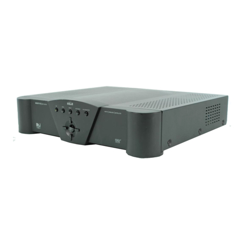
Enigma DR-81000 User manual

ENI G M A II
DR-81000
Digital Receiver
User Manual
CPM2 V2.20 build A430
LC2 V2.20 build A426
RC2 V2.11 build 9403

EN GMA DR-81000 Digital Receiver Version 2.00
Table of Contents
Table of Contents.........................................................................................................................2
1. Introduction..............................................................................................................................5
CPM2 Card............................................................................................................................................5
LC2 Line Cards.....................................................................................................................................5
RC2 Radio Receiver Card...................................................................................................................5
PWR2 Power Card................................................................................................................................5
Compatibility........................................................................................................................................5
System Overview..................................................................................................................................6
2. Quick Start................................................................................................................................7
Receiver Setup and Operation............................................................................................................
Unpacking............................................................................................................................................................7
ntroduction to Operation.....................................................................................................................................7
Bench Testing......................................................................................................................................
Power Up ............................................................................................................................................................7
Operation with the default programming..............................................................................................................7
Return to the default programming......................................................................................................................7
3. Installation................................................................................................................................8
Mounting the Receiver.........................................................................................................................8
Printer Connections.............................................................................................................................8
Computer Connections........................................................................................................................8
Ethernet Connection............................................................................................................................8
CPM Card Backplane Diagram............................................................................................................8
Telephone Line Connections..............................................................................................................9
Grounding.............................................................................................................................................9
Line Card Backplane Diagram.............................................................................................................9
Power Supply Card............................................................................................................................10
Power Supply Backplane Connections............................................................................................10
Removing and Installing Cards.........................................................................................................11
CPM2 Card........................................................................................................................................................11
LC2 Line Cards .................................................................................................................................................11
RC2 Radio Card................................................................................................................................................11
ENIGMA II Backplane View (Example)..............................................................................................11
4. The E IGMA II Controls ........................................................................................................12
The LCD Display................................................................................................................................................12
Power LED.........................................................................................................................................................12
Bat LED.............................................................................................................................................................12
Error LED...........................................................................................................................................................12
2

EN GMA DR-81000 Digital Receiver Version 2.00
Link LED............................................................................................................................................................12
Opt LED.............................................................................................................................................................12
RX LED..............................................................................................................................................................12
1..8 LEDs...........................................................................................................................................................12
D SPLAY key and LED......................................................................................................................................12
Function keys.....................................................................................................................................................12
ENTER key........................................................................................................................................................12
Arrow keys.........................................................................................................................................................12
5. CPM2 Card..............................................................................................................................13
General Information...........................................................................................................................13
Features..............................................................................................................................................13
CPM2 Startup Sequence....................................................................................................................13
Normal Operation...............................................................................................................................13
The Status Row.................................................................................................................................................14
List of Events.....................................................................................................................................................14
Review the List of Events...................................................................................................................................14
Change List Font Size ......................................................................................................................................14
Code display mode............................................................................................................................................14
Protected Mode Operation.................................................................................................................15
Entering Protected Mode...................................................................................................................................15
The Menu............................................................................................................................................16
Utilities ...............................................................................................................................................16
Report................................................................................................................................................................16
Print...................................................................................................................................................................16
Reset ................................................................................................................................................................16
Setup ..................................................................................................................................................16
Options..............................................................................................................................................................16
Time & Date.......................................................................................................................................................17
CPM2 Ports.........................................................................................................................................18
Serial Ports (COM A and COM B).....................................................................................................................18
Report Mode......................................................................................................................................................18
Receive Mode....................................................................................................................................................18
Program Mode...................................................................................................................................................18
Port Setup..........................................................................................................................................................18
Serial Port Setup................................................................................................................................................18
Serial Protocols..................................................................................................................................................20
Serial Port Status Display..................................................................................................................................22
USB Ports..........................................................................................................................................................22
Parallel Port.......................................................................................................................................................22
Printing...............................................................................................................................................................22
TCP/IP Options...................................................................................................................................23
TCP Socket Monitoring......................................................................................................................................23
P Based Reception...........................................................................................................................................23
Web nterface....................................................................................................................................................23
Remote Management........................................................................................................................................24
Connecting to the internet..................................................................................................................................24
6. LC2 Line Card.........................................................................................................................26
General Information...........................................................................................................................26
3

EN GMA DR-81000 Digital Receiver Version 2.00
Installation..........................................................................................................................................26
LC2 Line Card Features.....................................................................................................................26
Line Card Controls.............................................................................................................................2
Stand-by Mode...................................................................................................................................2
CPM2 Monitoring...............................................................................................................................................27
Call Reception...................................................................................................................................................28
2-way Audio Mode.............................................................................................................................................28
Call Termination.................................................................................................................................................28
Caller D Processing..........................................................................................................................................29
Operating in Stand-alone Mode........................................................................................................29
Line Card Menu..................................................................................................................................29
Audio Monitoring................................................................................................................................................29
Hang Up.............................................................................................................................................................30
Line Card Setup.................................................................................................................................................30
Line Card Status................................................................................................................................................31
7. RC2 Radio Card......................................................................................................................33
General Information...........................................................................................................................33
Installation..........................................................................................................................................33
RC2 Features......................................................................................................................................33
RC2 Operation....................................................................................................................................33
Radio Reception ................................................................................................................................33
CPM2 Supervision.............................................................................................................................................34
Radio Card Menu................................................................................................................................34
Audio Monitoring................................................................................................................................................34
RC2 Radio Card Settings...................................................................................................................................34
RC2 Card Status Display...................................................................................................................................35
8. Power Card.............................................................................................................................36
nputs and Outputs............................................................................................................................................36
Power Status Display.........................................................................................................................................36
Battery Testing...................................................................................................................................................36
Appendices.................................................................................................................................37
Appendix A: System Event Table (0000)..........................................................................................3
Appendix B: Supported Communication Formats IP......................................................................38
Appendix C: Supported Communication Formats PSTN................................................................38
Appendix D: Trouble Shooting Guide...............................................................................................39
4

EN GMA DR-81000 Digital Receiver Version 2.00
1. Introduction
The ENIGMA II DR-81000 is a multi-line, multi-format
P / PSTN / Radio digital receiver for commercial fire
and burglary monitoring. The base unit contains a
CPM Central Processing Card with IP support, and
a PWR Power Card. With additional LC2 Line
Cards, the receiver can be enabled to monitor up to
8 telephone lines. Adding an optional RC2 Radio
Card to the system enables radio receiver
functionality. The EN GMA DR-81000 can receive
and decode most of the popular and commonly used
communication formats, for both P and PSTN
reception. See Appendix B. for details
The EN GMA DR-81000 stores all events with time
and date stamped. All information is displayed on the
large LCD screen, and the events may be printed
and/or forwarded to a computer. To ensure security,
all programming functions, including the adjustment
of the real time clock and date is password protected.
CPM2 Card
The Central Processing Unit (CPM2) controls the
operation of the receiver. The CPM Unit incorporates
two serial ports, a high-speed USB port, a 10-BaseT
Ethernet interface for P reception and one parallel
printer port. The CPM Unit has two external inputs,
one for external acknowledge, and one for tamper
recognition. The CPM Unit also incorporates two
programmable outputs, which can be programmed to
follow different receiver status.
The CPM Unit features a 2000-event non-volatile
memory buffer. The contents of the buffer may be
browsed on the LCD screen. f the printer or
computer is off-line, the CPM2 Card will store the
incoming events in its buffer, and will automatically
forward them, when the connection restores.
The CPM2 controls the large graphical LCD display
of the receiver, which enables it to implement unique,
user friendly features like changeable display font
sizes, full line card control, and easy-to-use manual
programming.
LC2 Line Cards
Each Line Card (LC2) can monitor a telephone line.
The Line Cards contain a 500-event event memory to
record events and caller information. Caller
dentification capability is built-in and the telephone
number of the calling party can be displayed, printed,
stored in memory and forwarded to the automation
computer. The Line Cards also support the 2-way
audio listen-in.
The Line Cards are continuously supervised by the
CPM Unit to ensure uninterrupted communication.
Any trouble conditions are immediately reported on
the LCD screen and printer and/or forwarded to the
computer. The Line Card also verifies the
communication with the CPM Unit. n case of CPM
malfunction the operator will be advised with an
audible indication and the Line Cards will continue to
function in stand-alone mode - it will continue
receiving events and store them in its buffer. The
events will be forwarded to the CPM Unit after the
connection restores.
RC2 Radio Receiver Card
The Radio Receiver Card (RC2) acts as a special line
card in the system – it receives encoded messages
from radio transceivers (UHF, 440..450MHz). The
RC2 Card can handle up to 2 radio receivers, which
enables it to monitor 2 radio channels
simultaneously. The reception, decoding, storing and
forwarding of the messages work similar to the LC2
Line Cards. The Radio Card is also capable of stand-
alone operation in case the connection with the
CPM2 fails – it can store up to 500 messages in its
non-volatile buffer.
PWR2 Power Card
The Power Card supplies the power for the other
Cards in the receiver. t requires 16.5 VAC from a
115 or 230 VAC, 50/60 Hz, transformer. The Power
Card is equipped with automatic battery charger and
backup battery connections. n case of AC failure the
Power Card automatically switches to backup battery
power. The backup battery capacity can be between
7 and 15 Ah. The Power Card supervises the
presence of the battery and the battery capacity and
the current status is reported to the CPM Unit.
Compatibility
The EN GMA DR-81000 Digital Receiver is
compatible with the most commonly used automation
software packages. The receiver has been tested to
work with the following software:
−Alarm SyS
−S MS
−Microkey S S
−Cortex WinSC Security Commander
For other automation software, if not supported
directly, generally, selecting the Enigma XM88422 or
the Surgard MLR2 driver will provide compatible
support for the receiver.
5

EN GMA DR-81000 Digital Receiver Version 2.00
System Overview
−Standalone P receiver (server)
−Up to 8 PSTN analog lines per receiver
−Radio receiver – 2 channels (UHF 440..450MHz)
−2000-event non-volatile event buffer in the CPM2
−500-event non-volatile buffer on each line card
−Programming is stored in internal EEPROM in
the CPM2 and in each line cards
−Real-Time Clock and calendar in the CPM2
−2 independent fast RS232 ports
−1 parallel printer port
−2 USB ports (serial ports coupled)
−1 Ethernet port (10-BaseT) P Server
−Programmable serial port configuration
−Fast transmission of multiple events to the
computer and/or printer to ensure fast operator
response
−Continuous control of the cards by the CPM2
−Continuous check of the receiver-computer link
with “heartbeat” protocol
−Large graphical LCD screen
−nputs on the CPM2 card for external
acknowledge and tamper supervision
−2 Programmable Outputs on the CPM2 card
−P Multiformat receiver (C D, E2, S A)
−Support for various P/GPRS communicators
−Full S A P Event Reporting (DC-09) support
−Automatic ES-128 encryption support
−TCP Socket supervision, keep-alive support
−PSTN Multiformat receiver (pulse, DTMF, FSK)
−Caller D capability (Bellcore, ETS and DTMF)
−Telephone line supervision
−Contact D Support
−S A FSK Support (Level 3 with restrictions)
−Each line card has an output for 2-way audio
−Event libraries for plain language message
display capability.
−Built-in Contact D and S A Event Library
−User defined Custom Event Library option
−Easy management with EniTerm utility
−Remote management support via P/Ethernet
−High-performance Flash R SC microprocessors.
−Firmware Upgrade by user
−Uninterrupted Switching Power Supply with AC
monitoring and active battery test
−ndustry standard 19” system architecture
−Standard eurocard circuit board design for
reduced complexity and easy servicing.
−Highly reliable SMD technology
6

EN GMA DR-81000 Digital Receiver Version 2.00
2. Quick Start
Receiver Setup and Operation
Unpacking
Carefully unpack the receiver and inspect the device
for shipping damage. f there is any apparent
damage, do not try to turn on the equipment, and
notify your distributor immediately. The package
contents are the following:
•Enigma DR-81000 Digital Receiver
•AT Null-modem Cable
•USB Cable (A-mini)
•Terminals and battery cables
•User Manual, Operator Guide
Introduction to Operation
Please, refer to the following chapters of this manual
to help you through the installation and operation of
the EN GMA DR-81000 digital receiver.
Chapter 3. Installation
Chapter 4. Enigma II Controls
Chapter 5. CPM2 Card
Chapter 6. LC2 Card
Chapter 7 Power Card
Bench Testing
t is highly recommended the receiver be tested
before commencing the actual installation, becoming
familiar with the connection and setup of the device,
and the receiver programming to make the final
installation more straightforward.
The following items are required for testing:
•16.5V AC transformer
•12V 7Ah battery
•Router and P communicator for P testing.
•telephone line and a digital dialer or a control
panel with for PSTN testing
•Radio transceiver and Radio communicator for
UHF radio testing
Please, use a certified 16.5V AC transformer with a
minimum of 40VA to supply AC power to the receiver.
Connect the transformer to the AC input terminals on
the backplane of the Power Card. Connect the
battery cables to the BAT terminals with correct
polarity, but do not connect the battery to the cables
yet.
Power Up
Powering up the unit starts with applying AC power to
the unit. After that, connect the battery to the battery
cables. The CPM unit carries out a comprehensive
Power-on Self Test and tests all system components.
f the CPM finds any malfunctioning/unreliable
components during the POS test, it will stop, and
display the problem on the screen.
After the POS test had been finished, the CPM resets
the line cards in system, and will switch to event list
mode (normal operation).
Operation with the default programming
Without any changes to the factory default
programming, the receiver operates normally with the
following specifications:
•Default Program Access Password is EN GMA
•Default P address 192.168.1.240, P Server is
initialized at port 9999.
•Line cards answer to incoming calls on the
second ring
•Caller identification (Caller D) is enabled
•The handshake sequence is 2 x dual tone,
2300,1400 and FSK answer tone
•Reception of Extended formats is disabled
•Two Way Audio (listen in) is disabled
•The default setting for serial ports is 9600,8,N,1
•COM A (or USB A) is in report mode
•COM B (or USB B) is in receive mode
•Printer is off
•Heartbeat supervisory protocol enabled
heartbeat in every 30 seconds.
•Clock signal protocol is disabled
•External acknowledge is disabled
•Tamper recognition is disabled
When an event is received from P or from a line card
it will be displayed on the LCD screen with time and
date. Events coming in Contact D and S A format
are automatically decoded from the predefined event
libraries. For other formats, by default, only the
incoming code will be displayed. The events will be
reported to the computer via the serial port COM A.
f the computer is not connected, pushing the ENTER
button will silence the buzzer in case events are
pending. The manual acknowledgement is recorded
with time and date.
Return to the default programming
You can return to default programming at any time by
entering the menu and selecting the ‘Factory’ menu
item from the ‘Utils/Reset’ menu.
7

EN GMA DR-81000 Digital Receiver Version 2.00
. Installation
Mounting the Receiver
The EN GMA DR-81000 receiver is shipped by
default in a standard 3HE 19” desktop housing. With
the mounting holes on the front panel, the housing
can be installed in standard 19” rack cabinets.
NOTE: the feet of the desktop housing may have to
be removed when installing into rack cabinets.
NOTE: the LCD screen on the receiver is designed to
be viewed below eye level (12h viewing angle). f the
receiver has to be mounted above eye level, it might
be useful to angle the unit downward improving
visibility or readjust LCD contrast settings.
Printer Connections
Any Printers equipped with a parallel Centronics
interface can be connected to the EN GMA DR-
81000 receiver. To connect the printer to the
receivers parallel printer output use a parallel printer
cable.
IMPORTANT: Using parallel printer cable with only
one common ground wire is not recommended.
Computer Connections
Connect the automation computer to the EN GMA
DR-81000 serial COM A port using the supplied
cable, or to USB A using the supplied miniUSB cable.
f the supplied cable is not long enough, a serial Null-
modem cable can be used up to 15 meters in length,
and a longer miniUSB cable can also be used, if
necessary.
The port COM B or the USB B port can be used to
connect to the automation computer, too, in case
they are set to Report mode. The same type of serial
or USB cable can be used on COM B.
IMPORTA T: Please, do not use standard T-
modem (straight) cables for the serial ports. lways
use a null modem (crosslink) cable.
Ethernet Connection
The DR-81000 receiver can be connected to the
Ethernet network at its RJ45 modular 10 BaseT
terminal with a standard patch cable. Please, note,
that the connection must be made to a switch or
router on the network. The necessary setup for the
local network can be found in the TCP/ P section.
CPM Card Backplane Diagram
8

EN GMA DR-81000 Digital Receiver Version 2.00
Telephone Line Connections
Connect the telephone lines to the LC2 Line Cards
L NE modular jack with RJ11 4/6 pin modular cables.
For SDN connection, use one of the 2 analog
outputs of the SDN NT box.
The handsets for 2-way audio listen-in can be
connected to the same modular connector. The
incoming line is connected to the two inmost pins (3-
4), while the handset can be connected to the
neighbouring outer pins (2-5). Ensure, that the
handsets connected are off-hook, because leaving
the handsets on-hook will terminate 2-way Audio
Mode. Measure the impedance of the handsets to
check, if the line will be terminated with the proper
impedance when switching to the handset. On
normal telephone lines, it should be around 600
ohms. When used in PBX system 2-way audio
communication needs bridging resistors with the
same value as measured on the handset. Using
improper termination the line will be dropped when
switched to 2-way Audio Mode
Grounding
To achieve the best resistance against static and
electric noise and electromagnetic interference (EM )
connect the metal casing of the receiver to a
grounding point. Note that the grounding of the frame
has to be separate to the grounding of the Line Card
interfaces.
Proper grounding is essential also for the reliable
electric shock and lightning protection of the
telephone line interface of the Line Cards. Connect
the protective ground terminal of the Line Card to a
proper grounding point.
IMPORTA T: Do not connect the protective ground
terminals directly to each other, or to the metal
frame. Connect the terminals to the grounding pole
individually with separate wires. NEVER connect the
protective ground to the power/signal ground of the
receiver!!!
Line Card Backplane Diagram
9

EN GMA DR-81000 Digital Receiver Version 2.00
Power Supply Card
The Power Supply of the receiver is housed in the
Power Card. The Power Supply requires 16.5 VAC
as input, and has a 13.5 VDC stabilized power output
with fuse and a 13.8 VDC stabilized battery charging
output with fuse.
Using a 16.5 VAC 40VA transformer connect the AC
power to the Power Card. Connect the battery cables
to the battery outputs with the supplied terminals.
Using a 7 Ah backup battery is recommended to
avoid battery test problems.
t is very important to connect protective ground
(shielding) to the grounding terminal on the back of
the PWR card. This ensures the protection against
static discharge. A standard M5 nut is provided at the
earthing point for connection. This point can be
connected to the ground terminal of the AC outlet.
Ensure that all connections have been made
correctly.
Power Supply Backplane Connections
10

EN GMA DR-81000 Digital Receiver Version 2.00
Removing and Installing Cards
The receiver does not have to be powered down
while components of the system are removed or
installed.
CPM2 Card
Remove the 4 retaining screws on the back panel of
the Card. Carefully pull the Card out of the rack
housing. nstallation is the reversal of removal. Push
the Card carefully and firmly back to its place, then
mount the retaining screws. After plugging in, the
CPM Unit will make a cold start.
LC2 Line Cards
Remove the 2 retaining screws on the back panel of
the Card. Carefully pull the Card out of the rack
housing. nstallation is the reversal of removal.
RC2 Radio Card
Remove the 4 retaining screws on the back panel of
the Card. Carefully pull the Card out of the rack
housing. nstallation is the reversal of removal. f you
install a new RC2 card, please, remove the blank
cover of the radio card slot first.
Note, that there is a dedicated position for the PWR, CPM
and RC cards, which cannot be installed in other positions.
lso, for the LC cards, the actual Line Card number
depends on the position the Line Card installed into. If
possible, please fill up the cards from right to left (1 to 8).
E IGMA II Backplane View (Example)
11

EN GMA DR-81000 Digital Receiver Version 2.00
4. The ENIGMA II Controls
The LCD Display
The 240 x 128 resolution graphical LCD can display
up to 5 events at a time (10 with small fonts). The
system status information and the time and date can
be seen on the top of the screen. On the bottom, the
menu is displayed. n info display mode, the display
shows the status of the line cards int he system, and
the status of the ports and the power supply.
Power LED
The blue Power LED indicates the operation of the
receiver.
Bat LED
The red Bat LED shows the status of the battery and
the AC power. f this LED is off, then there is no
power problem. f it is lit, then it indicates AC power
loss (the system is operated on battery power). The
flashing Bat LED shows battery problem – change or
recharge the connected battery. f the LED blinks
fast, it indicates a problem of the power supply.
Error LED
The red Error LED lights up if there is any pending
problems in the receiver. Please, review the info
display on the top line of the LCD Screen.
Link LED
The Link LED shows the status of the PC/Ethernet
connection. f there is a working serial or USB link
with the PC, then it should light up green. Red light
shows that the Ethernet cable is plugged in – in case
there is an active link on the serial and USB ports at
the same time, the light will be yellow. f this LED is
not lit, that shows connection problem – the receiver
is operating in standalone mode.
Opt LED
The Opt LED is the display for the optional Radio or
GSM Receiver Card. This LED is not lit during normal
operation.
RX LED
The RX LED shows the traffic status of the optional
Radio or GSM Cards. Green light means, that there
is reception in progress (packet received), while red
light indicates transmission in progress (packet sent)
– in case repeater (RX/TX) mode is enabled. During
Flash Update of the card, the LED blinks slowly
green.
1..8 LEDs
The LEDs 1..8 display status information of the line
cards. Continuous green light indicates standby
mode – the line is ok, and the card is waiting for call.
Ring is signalled by fast blinking – it turns to yellow
when the Line Card answers the call and receives the
incoming communication. f the LED is off, and lits up
red shortly in about every five seconds, that means
there is a problem with the telephone line. During
Flash Update of the card, the LED blinks slowly
green.
DISPLAY key and LED
This button changes the display modes of the LCD
screen. The default display mode is the event list –
the incoming events are listed on the screen with
timestamp. Pressing the Display button will change
the screen into info display mode. (The LED beside
the buton will light up) – in this mode the current
status of the line cards and the most important
system ports and components can be viewed.
Pressing the Display button again returns to the
event list mode. More about the event list and info
display modes can be found in Chapters 5, 6, 7 and
8.
Function keys
There are four function buttons below the LCD
display. These buttons have context-sensitive
functions – the actual function is displayed on the
bottom line of the LCD right above the buttons.
ENTER key
The Enter key can be used to manually acknowledge
the incoming events in the event list mode (in case
there is no link to the PC). n setup dialogs, it can be
used to confirm options and save changes.
Arrow keys
With the arrow keys the list of events can be browsed
up and down in event list mode. n info display mode,
they can be used to navigate between the line cards.
n setup dialogs, they navigate between the data
fields.
12

EN GMA DR-81000 Digital Receiver Version 2.00
5. CPM2 Card
The CPM2 Card is the central processing Card of the
EN GMA DR-81000 that controls the line cards and
forwards the information from the line cards to the
printer and the central station computer. The CPM
can monitor up to 8 line cards and a radio card.
General Information
The CPM2 incorporates a high-speed R SC micro-
controller. This allows very fast and effective system
operation and also unique features, like handling of
big, graphical display and implementing context-
sensitive menus and dialogs for easy, user-friendly
and efficient programming of the system.
Features
•High-speed R SC processor and multi-tasking
•Flash technology - upgradeable firmware
•Standalone P Receiver Server
•Fast internal communication with system cards
ensures no delay in transfer information between
the CPM2 and the line cards. The CPM2 polls all
the line cards in less than 1 second.
•Up to 2000 event non-volatile alarm memory
•Large, graphical LCD display – user-friendly
environment
•List, browse and examine the line card messages
on the screen.
•Selectable font size on the LCD to improve
display visibility / data overview
•Context menus and dialogs help programming
and diagnostics
•User definable event libraries
•2 RS-232 serial ports, COM A and COM B
•2 USB 2.0 CDC (A and B virtual serial ports)
•10 BaseT Ethernet interface
•Serial port data rates can be set from 300 to
57600 baud. Serial port data protocol (data bits,
parity) programmable
•External acknowledge input
•2 OC Programmable Outputs to follow different
system status
CPM2 Startup Sequence
After power-up, the CPM2 waits for flash upgrade
access for 5 seconds. During this delay, Starting up
is displayed on the screen.
After the startup delay the CPM2 executes the
Power-On Self Test sequence (POS Test). t verifies
the function of the system components and
interfaces, the integrity of the program memory, the
data memory buffer and the flash libraries. The steps
of the POS Test are displayed on the screen. f the
CPM finds an error during the self test it will stop,
beeping and the problem will be displayed on the
LCD.
Figure 1. Startup and POS Test
After the POS Test is completed, the CPM Unit will
enter normal operating mode.
ormal Operation
n normal operation, the CPM2 receives messages
from the line cards, displays them and forwards them
to the computer and / or to the printer. f a computer
with automation software is connected to the
receiver, the CPM2 requires minimal interaction from
the central station operator. The LCD displays the
events in a list, the status row at the top, and the
main menu at the bottom of the screen. (Event List
Mode)
Figure 2. Event List Mode
13

EN GMA DR-81000 Digital Receiver Version 2.00
The Status Row
The status row is the topmost row of the LCD display.
t shows pending receiver problems and system
messages. f there are more problems and messages
to display at a time, they will be displayed one by
one.
On the right of the status row the current time and
date is displayed.
The protected mode of the receiver is indicated with a
small key displayed in the status row. The local
programming of the receiver and some of the utility
functions are accessible only in protected mode.
List of Events
The events received by the Line Cards are displayed
on the LCD screen in a list. The rows of the list
represent the individual events; the current event is
highlighted in the list of events with inverse display.
(see Figure 2.) The display is as follows:
1234 Panic 01 2 15:40:02
n the first column, the account number is displayed,
in this case 1234. Account number 0000 represents
the service and trouble events of the receiver. The
account number can be up to 6 digits.
The second column shows the event information. The
event information can be different depending on the
incoming format, the preset and user defined
libraries. Examples for event information:
21 Normal event, code 21
Panic 1 S A Event code NPA1
Burglary 01 005 Contact D code E13001005
Custom Event 01 User defined event in the user
library as “Custom Event 01”
CALL: 12345 7 Calling number “1234567”
The event information contains all data related to the
event such as group/partition and zone/user
numbers. More about preset and user define libraries
in the Libraries section.
The third column displays the number of the line
card, from which the event was received. The line
card numbers can be between 1 and 8. The two
optional radio channels are represented by A and B.
System events are displayed with S,and events
received via the TCP/ P port are shown with IP. f
there are more receivers linked together, the line card
numbers of the linked receivers are displayed with
the extra character Xadded before them.
The fourth column contains the time of the event.
Every event, including the service and trouble events
of the receiver and the manual acknowledge, are
stored in the memory buffer with timestamp. That
allows the receiver to forward the messages to the
computer (with Clock Signal Protocol) and printer
with the real time and date of the event, even if the
message is forwarded later.
Review the List of Events
The list of events can be reviewed with the use of the
arrow keys. Pressing Left and Right will move the
highlighted cursor backwards and forwards in the list,
allowing to view the contents of the memory buffer.
Note, that incoming events have priority over
browsing, so that if none of the arrow keys are
pressed for 5 seconds, the CPM2 will automatically
interrupt review mode, and return to the bottom of the
list, if any new events come in with the newly
received event highlighted in the last line.
Change List Font Size
n event list mode, in the main menu, pressing the F1
function key (“Font”) will change between normal and
extended display font sizes. The change is instant;
the list of events and the status row will be displayed
in the selected font size.
Figure 3. Event List with small fonts
Code display mode
The receiver will display events in a human readable
form, in case it can decode the actual event from its
built-in, or custom event libraries. Pressing the F2
function key (“Codes”), the receiver can be forced to
display the incoming code, even it has been
successfully decoded, and its description is
displayed.
14

EN GMA DR-81000 Digital Receiver Version 2.00
Protected Mode Operation
n protected mode, the receiver is operating the same
way as in normal mode, except that all the menu and
local programming functions are accessible. A small
key displayed in the status row indicates protected
mode operation.
Note that not all the CPM and line card parameters
can be programmed locally. Some of the parameters
can only be programmed by the user with the
EN GMA Programmer Software via the serial ports..
OTE: If the receiver is in protected mode it will
automatically exit protected mode after 3 minutes of
inactivity.
Entering Protected Mode
f a desired utility or programming function requires to
be run in protected mode, the receiver will prompt for
entering the system password.
Figure 4. Password Entry
The password can be entered with the function keys
a similar way as it is well known and used to with
mobile phones. The alphabet is spread up between
the four function keys, 7-7 characters assigned to
each. Pressing a function key first will enter the first
character assigned to it, pressing it again shortly will
enter the second assigned character and so on. f the
desired character is reached, leaving the function key
untouched for 2 seconds will finalize the character,
and the cursor will step onto the next position.
Pressing a different function key will also finalize the
character.
Stepping back is possible with the Left arrow key, this
will erase the last entered position and move the
cursor one back.
Note, that at password entry, the finalized characters
are replaced with a *. This makes hi-jacking harder,
but also requires the user to concentrate more on the
entry.
After the desired password is entered, pressing the
Enter key will verify it. f the password is correct, the
receiver will enter into protected mode, and an
“Access Granted” message will be generated. f the
password is incorrect, the receiver will return to
normal operation and an “Access Denied” message
will be generated. Pressing the Display button will
cancel password entry at any time.
The factory default system password is “EN GMA”.
The passwor can be changed with the EniTerm utility,
see the “EniTerm Software Manual” for details.
15

EN GMA DR-81000 Digital Receiver Version 2.00
The Menu
The Enigma has a context-sensitive menu system.
The menu is displayed on the bottom of the screen,
the items (functions) can be activated by pressing the
Function keys below them.
Figure 5. The Main Menu
At different levels of the menu, the actual functions
assigned to the Function keys are changing
accordingly.
Some of the menu functions are free accessible,
some of them can only be accessed in protected
mode.
Utilities
The utility functions can be reached with pressing the
“Util” button (F3) in the main menu.
Figure 6. The Util Menu
Report
The receiver stores the last 2000 events in the
memory even after it had reported to the computer or
printed. At this menu some (last 50, today) or all of
these events can be resent to the central station
computer regardless that they were reported before
or not. This menu is protected.
Print
This menu works the same way as the Report menu,
except that it sends the contents of the memory
buffer to the printer. This menu is protected.
Reset
This menu allows the central station operator to make
a full receiver reset. This can be useful if receiver
malfunctions encountered. There are three different
levels of system reset. The Factory reset will reset
the receiver parameters to default. This option might
be useful, if the user has misprogrammed the unit
and wants to return to the factory default state. This
option is protected.
Figure 7. The Reset Menu
The Memory function will erase the contents of the
memory buffer. This option is protected.
The Reset function will only do a warm-reset. The
receiver will be restarted from the POS Test, but the
parameters and the contents of the memory will be
left unchanged. This option is not protected.
WAR I G: Use the Memory and Factory commands
with extreme caution because these commands will
erase the contents of the memory buffer that may
result in data loss.
Setup
The programming functions of the receiver can be
accessed under this menu.
Figure 8. The Setup Menu
Options
The general options of the CPM2 can be set at the
Options menu. The menu is protected. When
selected a dialog will appear as follows:
Figure 9. CPM Options
The currently selected field is flashing. Skip between
fields with the Left and Right arrow keys. The field
contents can be increased with the + (F1) button and
16

EN GMA DR-81000 Digital Receiver Version 2.00
decreased with the – (F2) button. Pressing a button
continuously will repeat the action until the button is
released. After the fields are set correctly, press the
Enter key to save the set values. Pressing the Cancel
(F4) or Display button will exit the dialog without
making any changes.
Mute Buzzer
This option can silence the buzzer for debugging or
servicing purposes. Enabling this option is not
recommended for central monitoring stations,
because the receiver will not beep when an event
comes in and the PC Link is broken. The default
setting is disabled.
External CK
The operation of the external Acknowledge input of
the receiver can be enabled and disabled here. When
enabled, the events can be manually acknowledged
by a normally open pushbutton connected to the
external Acknowledge input of the receiver. The
default value is disabled.
Receiver Tamper
When enabled, a short between the receivers tamper
inputs will generate a “Receiver Tamper” status
event. This can be used to record receiver tampering,
when the receiver is installed in a closed cabinet with
access doors. The default setting is disabled.
Printer
The operating mode of the printer can be set here.
The available options are as follow:
OFF The printer is disabled, nothing will
be printed.
FULL All incoming events will be printed.
BACKUP A The events will be printed if the
connection on COM A is broken.
BACKUP B The events will be printed if the
connection on COM B is broken.
The default setting is printer off.
Link Mode
As there are two independent serial ports are
implemented on the receiver, and both can be
configured to report mode at the same time, it is
necessary to set, when the link with the PC should be
considered ok. There are two options available here:
A OR B The link to the PC is considered
good, if there is connection in any
of the two serial ports.
A AND B The link to the PC is considered
good only if both serial ports are
connected.
The default setting is A OR B, so that if any of the
ports is connected to the PC, the link will be
considered ok.
SI Messages
For S A Level 2, multiple events can be transmitted in
one single event block. This option decides, whether
the event block should be sent to the PC as is, or it
should be splitted to individual events (for S A Level 1
protocol compatibility reasons). The two possibilities
are:
BLOCK The event block is handled as
received.
SPLIT The event block is split to
individual events.
The default setting is block mode
LCD Contrast
The Contrast of the LCD Screen can be set here. Any
values between 0 and 15 can be given, the higher
value will result in a higher contrast. The default
setting is 0.
Time & Date
The real time clock of the CPM2 can be set at this
option. This function is not protected. A dialog box
appears when selecting the menu item:
Figure 10. Set Time and Date
The navigation and setting of the fields can be done
the same way as it is described at the CPM Option
settings. The setting of the system time and date
generates a “T ME/DATE SET” event so that the
system time change will be recorded in the event list.
17

EN GMA DR-81000 Digital Receiver Version 2.00
CPM2 Ports
The EN GMA DR-81000 digital receiver is equipped
with two RS232 serial ports, one Centronics parallel
port, one high-speed USB port and an Ethernet port.
Serial Ports (COM A and COM B)
The Serial Ports are the main communication ports of
the CPM2. They are almost identical, except one
important feature – COM B is internally connected
with the USB port, so that if the USB port is in use,
COM B cannot be used at the same time.
The serial ports can be configured either as receiver
or reporting ports. Regardless of the port
configuration, both ports can be used for remote
programming of the receiver.
Report Mode
The primary function of the serial ports is the Report
Mode. When the CPM2 receives a message from a
line card, radio, or from the TCP/ P port or an
external receiver, or there is a CPM2 status event, it
records the event in the memory buffer then forwards
the event to the computer via the reporting port and
awaits acknowledge signal from the computer.
Normally a positive acknowledge (ACK) is received,
and the receiver steps to the next reportable event. f
no acknowledge or negative acknowledge signal
(NACK) is received, the CPM2 will try to resend the
event 5 more times. f all attempts fail, the receiver
generates a “COM x Error” event, (where x is A or B
depending on the actual port number) and will keep it
in the memory buffer while tries to report it repeatedly
until it succeeds. The CPM2 can store up to 2000
events in its memory buffer if the link with the central
station computer is broken.
f the receiver succeeds to report the event after a
communication failure, a “COM x Restored” event will
be recorded. After the communication link is restored,
the CPM2 will send all pending reportable events
from its memory buffer to the computer the same
way. This method provides reliable and supervised
communication between the CPM2 and the central
station computer.
The reporting port is also supervised with heart-beat
signals. The heart-beat signals are used to test the
communication link between the receiver and the
central station computer when there is no reportable
event in the memory buffer. n this case the receiver
sends so called heart-beat signals to the computer in
a programmed time interval and requires
acknowledge for that. f the acknowledge is missing
or negative, it assumes that the computer is failed,
and results in a “COM x Error” message.
f the automation software is not compatible with
heart-beat supervision, the heart-beat signals can
also be turned off (See Port Options).
Receive Mode
The secondary function of the serial ports is Receive
Mode. t can be used to receive serial protocols from
other receivers (E.g. SurGard or another EN GMA).
All the events received on the serial port are stored in
the CPM2 as they would received on a virtual line
card, and the prefix X will be attached to their line
card numbers. These events will be listed together
with the events received on the physical line cards of
the receiver.
This function can be used to link multiple receivers
through the serial ports and act as one, big receiver
from the view of the central station computer. (E.g.
when there are more than 8 telephone lines at the
central station)
With this ability, the receiver can also be used to
upgrade older systems.
Program Mode
Any of the two serial ports can be used for remote
programming of the receiver. To access remote
programming, the EniTerm software can be used. For
a detailed description of remote programming,
please, refer to the EniTerm Software Manual.
When commencing serial programming, the receiver
will generate a “Program Mode” message. f the time
and date is set during programming a “Time/Date
Set” message will be stored, if any parameter of the
receiver is changed a “Program Change” event will
be recorded. Upon termination of the serial
programming a “Program End” event will be stored in
the memory buffer.
Port Setup
The features of the serial ports and the TCP/ P
interface options can be set in this menu. The menu
is protected.
Figure 11. The Ports Menu
Serial Port Setup
The serial ports COM A and COM B are independent
of each other and their parameters can also be set
18

EN GMA DR-81000 Digital Receiver Version 2.00
independently. However, as their operation is
identical, their parameters are set similarly.
Figure 12. Serial Port Settings
The navigation and setting of the fields can be done
the same way as it is described at the CPM Option
settings.
Port Function
This option selects the basic behavior of the given
port. There are two options available:
REPORT n report mode, the events are
reported via the port to the PC.
RECEIVE n receive mode, the port can be
used to connect to other receivers
and receive messages from them.
The default setting for COM A is Report Mode, and
for COM B is Receive Mode.
OTE: The remote programming features do not
depend on the selected port function, so that serial
programming access is possible either for report or
receive mode ports.
Report Option
This setting selects the protocol set for Report Mode
serial port. The options are:
COMPATIBLE n this case, the serial protocols
used are compatible with the
Enigma XM88422 and SurGard
MLR2 DG receivers.
E2 CUSTOM The E2 protocol set utilizes the
possibilities in the new reception
features of the Enigma 2
receiver, however, they might not
be compatible with all automation
software.
The default setting is Compatible Mode. For detailed
specifications of Compatible Serial Protocols, please,
refer to the Serial Protocols section.
Port Settings
Here the asynchronous protocol for the serial port is
set – port speed, number of databits and parity. The
port speed can be set between 300 and 57600 bps,
the number of databits can be set to 7 or 8, and the
parity can be choosen as none, even or odd.
The default setting is 9600, 8 databits, no parity.
OTE: The number of stopbits is always set to 1.
This option is not changeable.
Receiver Number
n multi-receiver environments the automation
software might have to be able to separate events by
receivers. The receiver number identifies the receiver
for the computer – the value can be set between 1
and 255 and has to be unique. The default setting is
01 for COM A and 02 for COM B.
Clock Signal
The insertion of the Clock Signal Protocol can be
turned on and off here. The Clock Signal Protocol is
used to transmit time and date information together
with the event to the computer. The default setting is
off. The Clock Signal Protocol can also be
programmed to transmit the year or the second of the
event. The default is to transmit the second of the
event.
HB Monitor
This option defines, that if the port is in Receive
Mode, it should monitor the heart-beat signals of the
connected receivers. By default this option is
disabled.
Heartbeat Time
Defines the interval of the heart-beat signals sent by
the receiver to the computer to verify the serial
connection. The interval can be set between 01 and
256 seconds. Programming 0 will disable the heart-
beat signals if the automation software is not
compatible with heart-beat protocol. The default
value is 30 seconds.
19

EN GMA DR-81000 Digital Receiver Version 2.00
Serial Protocols
The receiver uses different serial communication
protocols for the connection to the automation
software on the central station computer. Which
protocol is used depends on which format has the
event that has to be forwarded to the computer. The
serial protocols used by the EN GMA receiver are the
following
Basic Signal Protocol
The Basic Signal Protocol is the mostly used protocol
by the receiver. Receiver status events and most of
the events received by the Line Cards are forwarded
to the CPM using this protocol. The protocol format
is:
1RRLssssAAAAAAssGYYY[DC4]
Where:
1Protocol D
RR Receiver number
LLine Card D
AAAAAA Account number
GArea/Group number
YYY Event code
[DC4] Terminator, 014h
Heart-beat Protocol
The Heart-beat Protocol is a special derivate of the
Basic Signal Protocl. This protocol is used to
supervise the connection between the digital receiver
and the computer. t is sent periodically in a
programmable time interval and the computer should
positively acknowledge it for verification.
1RR0sssssssssss@ssss[DC4]
Where:
1Protocol D (Basic Signal)
RR Receiver number
@Heart-beat signal
[DC4] Terminator, 014h
SI Level 1 Protocol
The S A Level 1 Protocol is used to forward events
received in S A format. When multiple events are
received in one S A data block (S A level 2 and 3),
and the receiver is programmed to split the block to
individual messages then reports them with this
protocol.
3RRLssssAAAAAAXXYYYY[DC4]
Where:
3Protocol D
RR Receiver number
LLine Card D
AAAAAA Account number
XX S A Event code or modifier
YYYY Zone code/user code/time/date info
[DC4] Terminator, 014h
Caller ID Protocol
This protocol is used to forward Caller D information
to the automation software.
4RRLssAAAANNNNNNNNNN[DC4]
Where:
4Protocol D
RR Receiver number
LLine Card D
AAAA Account D, (0000 if com failed)
NNNNNNNNNN Calling Number
[DC4] Terminator, 014h
Contact ID Protocol
The Contact D Protocol is used to send messages
received in Contact D format to the computer
5RRLs18AAAAQXXXYYZZZ[DC4]
Where:
5Protocol D
RR Receiver number
LLine Card D
AAAA Account number
QEvent Qualifier E – new event or
open, R – restore or close, P –
previous event
XXX Class and event code
YY Group/Area number
ZZZ Zone/User number
[DC4] Terminator, 014h
20
Table of contents
Other Enigma Receiver manuals
