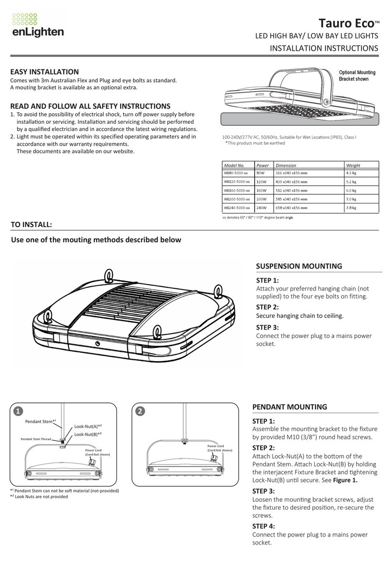
enLighten Vico BL06 Series User manual

Mounting
1. Remove diffuser cover;
2. Turn knobs to release and remove the gear tray. For emergency units, carefully unplug the green
indicator cable (see picture right);
3. Feed mains cables into fitting and mount luminaire base to ceiling using the mounting brackets;
4. Hang gear tray onto luminaire base using the hanging clips;
5. Connect mains wiring to terminal block —see Wiring section;
6. Emergency Models Only - plug green indicator cable into driver. Ensure correct polarity is maintained
by keeping the raised imprint & ink mark away from driver (see picture right);
7. Emergency Models Only - connect plug from battery cable to driver & record date of
commissioning on battery;
8. Adjust microwave sensor settings as required —see Microwave Sensor Settings section.
9. Secure the gear tray and diffuser onto the base.
Wiring
Standard model Emergency model –Non-switched Emergency model –switched
The emergency light
requires permanent
electrical supply and permanent
active must not be switched.
The permanent active and switched
active have to be energised for the
fitting to illuminate. If the switched
active is turned off then the battery
will charge but the fitting will not
illuminate in normal mode.
Emergency Models: Indicator & Simulation of Normal Power Supply Failure
Red LED ON = Charging
Red LED OFF = Battery fully charged
Green LED ON = Mains supply active
Green LED OFF = Mains supply failure
TEST BUTTON Press & hold the Test button to simulate normal power supply failure. This will trigger emergency mode
switching LED supply from 240V supply to battery. Releasing the button will restore normal power to the luminaire.
2. & 6. The raised imprint
and ink marking should be
facing away from the driver.
7. Battery Plug
Permanent/ Unswitched
Acve
Permanent/ Earth Neutral Switched
Unswitched Acve
Acve
Live Earth Neutral Earth Neutral
Loop
If neither the green nor the red LED is on, check the mains wiring and ensure that the green indicator cable is connected in the correct polarity.
Connued next page
Vico LED Batten
Installation Instructions
BL06xx, BL12xx, BL15xx models
NEW:Half-power option available by changing the dip-switch on the driver.
Maximum timer setting changed to 10 minutes
NOTE: ALL ELECTRICAL WORK MUST BE CARRIED OUT BY A LICENSED
ELECTRICIAN AS PER THE LATEST AS 3000 WIRING REGULATIONS.
WARNING: ALL MAINTENANCE, SUCH AS BATTERY CHANGE ON THIS LUMINAIRE, TO BE
PERFORMED BY A QUALIFIED PERSONNEL ONLY. DE-ENERGIZE ALL SUPPLIES BEFORE
MAINTENANCE.
• This luminaire contains non-user replaceable lamps. Do not touch LEDs during installation or mainte-
nance or put gear tray facing downwards onto surface. Warranty void if LED damage found.
• All entry points should be sealed properly to maintain the IP65 rating of the fitting. Warranty void if
water damage found.
It is the responsibility of the installer to ensure the following to avoid premature battery failure:
• Emergency fittings should be installed within 3 months after purchase as extended storage may
shorten the battery life.
• After connecting the battery, mains power should be supplied to the fitting within 7 days.

8. Restore mains power to the unit;
9. Recycle battery. Contact your local battery recycler for details
on how to recycle the LIFEPO4 batteries.
Half Power Switch
In areas where there is less light required, the full and standby power can be
set to half. Default setting: Full power.
Microwave Sensor Settings
The microwave sensor inside the diffuser is an active motion detector
that emits a high frequency electro-magnetic wave (5.8GHz) and
receives its echo. If it is necessary to check or adjust microwave sensor
settings to suit the local conditions, remove the diffuser.
Detection Area
Sensitivity can be adjusted to suit local conditions.
If the sensor detects motion outside the desired detection area, reduce
detection area setting to a lower value. Default setting: 100%.
Hold Time
Refers to the time the luminaire remains at 100% after motion is no
longer detected. Recommended value: 30 seconds for stairwells/
corridors, 90 seconds for car park parking bays.
enLighten recommends to use permanently-on fittings in car park
driveways.
The microwave sensor is inside the diffuser
→
Standby Level / Twilight Ratio
Refers to the illumination level after motion is no longer detected. Light
can also be set to permanently-on. Default setting: 20%.
Twilight Time
Refers to the time period the luminaire remains at standby level before
switching off. Recommended value: Infinity - fitting remains at
standby level during periods of no occupancy.
Battery Replacement
This luminaire requires a change of battery when it no longer meets its
rated duration of operation i.e. 90 minutes after receiving full charge.
Follow the below instructions to carry out battery replacement:
All electrical work must be carried out by a licensed electrician.
1. Isolate unit from mains power;
2. Remove diffuser and release gear tray;
3. Unplug battery plug from driver;
4. Remove battery from battery holder;
5. Insert new battery into battery holder, note the date of
commissioning on the battery;
6. Plug battery cable into driver;
7. Secure gear tray and diffuser onto luminaire base;
NOTE: The light must be operated within its specified operating parameters and in accordance with our warranty requirements.
These documents are available on our website.
Twilight Time
Dipswitch→78Time
ION ON 0 seconds (no standby)
II OFF ON 90 seconds
III ON OFF 3 minutes
IV OFF OFF Infinity
(always in 20% standby)
Hold Time
Dipswitch→34Time
ION ON 5 seconds
II OFF ON 30 seconds
III ON OFF 3 minutes
IV OFF OFF 10 minutes
Standby Level / Twilight Ratio
Dipswitch→56Standby light output
ION ON 20%
II OFF OFF 100%
(light permanently-on/sensor
disabled)
Detection Area
Dipswitch→12Range
ION ON 100%
II OFF ON 75%
III ON OFF 50%
IV OFF OFF 25%
Half power switch Operating mode
ION Half power
II OFF Full power
Push lever down and
slide baery out
The battery is in a battery holder on the gear tray.

Key Luminaire Specifications
Model Version Power Rating Ambient
Temperature
Emergency
Classification
Battery
BL15ES Sensor Emergency 200-240V 50/60Hz, 44W 0°C to +40°C Maintained
C0: D80; C90: D50
6.4V 3000mAh LiFePO4
BL15E Emergency 200-240V 50/60Hz, 44W 0°C to +40°C Maintained
C0: D80; C90: D50
6.4V 3000mAh LiFePO4
BL15S Sensor 200-240V 50/60Hz, 42W -20°C to +40°C n.a. n.a.
BL15 Standard 200-240V 50/60Hz, 42W -20°C to +40°C n.a. n.a.
BL12ES Sensor Emergency 200-240V 50/60Hz, 36W 0°C to +40°C Maintained
C0: D80; C90: D50
6.4V 3000mAh LiFePO4
BL12E Emergency 200-240V 50/60Hz, 36W 0°C to +40°C Maintained
C0: D80; C90: D50
6.4V 3000mAh LiFePO4
BL12S Sensor 200-240V 50/60Hz, 30W -20°C to +40°C n.a. n.a.
BL12 Standard 200-240V 50/60Hz, 30W -20°C to +40°C n.a. n.a.
BL06ES Sensor Emergency 200-240V 50/60Hz, 18W 0°C to +40°C Maintained
C0: D100; C90: D50
6.4V 3000mAh LiFePO4
BL06E Emergency 200-240V 50/60Hz, 18W 0°C to +40°C Maintained
C0: D100; C90: D50
6.4V 3000mAh LiFePO4
BL06S Sensor 200-240V 50/60Hz, 16W -20°C to +40°C n.a. n.a.
BL06 Standard 200-240V 50/60Hz, 16W -20°C to +40°C n.a. n.a.
C0 & C90 Orientation
for Emergency Luminaire
enLighten Australia Pty Ltd
www.enlighten.com.au 8 / 78 Reserve Road Artarmon NSW 2064 T: 02 8084 6971
August 2020 E&OE
Dimensions
This manual suits for next models
14
Other enLighten Light Fixture manuals
Popular Light Fixture manuals by other brands
Aurora
Aurora AU-HB200 instructions
Bayside
Bayside BRISTOL installation instructions
Larson Electronics
Larson Electronics HALP-96-2L-LED instruction manual
Philips
Philips CWBU installation instructions

Red Dragon
Red Dragon patio light owner's manual
Original BTC
Original BTC DAVEYLIGHTING 7679 instruction manual

Armstrong
Armstrong Zumtobel Ceiling Lighting System brochure
NOMA
NOMA Carriage Light with Motion-activated... Installation and operating instructions
Chauvet
Chauvet Rogue R1 user manual
Gavita
Gavita Pro line HortiStar 600 SE EU manual

for Living
for Living 25050 operating instructions
Lampo
Lampo WRLED Series instruction sheet
