ENMET AM-5150 User manual

ENMET Corporation
PO Box 979
Ann Arbor, MI 48106-0979
www.enmet.com
Manual part number
80003-550
MCN-453, 07/19/11
AM-5150
Ambient Air Monitor
Manual

Table of Contents
1.0 INTRODUCTION................................................................................................................................................................1
1.1 UNPACK..............................................................................................................................................................................1
1.2 CHECK ORDER ....................................................................................................................................................................1
1.3 SERIAL NUMBERS ...............................................................................................................................................................1
2.0 COMPONENTS OF THE AM-5150..................................................................................................................................2
2.1 AM-5150 ELEMENTS...........................................................................................................................................................2
2.2 AM-5150 OPERATIONAL FEATURES...................................................................................................................................2
2.3 CIRCUIT BOARD FEATURES.................................................................................................................................................3
3.0 INSTALLATION OF THE AM-5150................................................................................................................................4
3.1 MOUNTING AM-5150.........................................................................................................................................................4
3.1.1 Wiring the AM-5150 ..................................................................................................................................................4
3.1.2 Power Supply..............................................................................................................................................................4
3.2 SENSOR LOCATION .............................................................................................................................................................5
3.2.1 Sensor Hook-up...........................................................................................................................................................6
3.3 RELAY CONTACTS ..............................................................................................................................................................7
4.0 OPERATION .......................................................................................................................................................................8
4.1 START UP AM-5150...........................................................................................................................................................8
4.1.1 Typical Start Up..........................................................................................................................................................8
4.2 NORMAL DISPLAY MODE....................................................................................................................................................9
4.2.1 Alarm Conditions AM-5150.......................................................................................................................................9
5.0 MAINTENANCE...............................................................................................................................................................10
5.1 MAINTENANCE MENUS.....................................................................................................................................................10
5.2 CALIBRATION OF THE AM-5150 .......................................................................................................................................12
5.2.1 Exit Maintenance Menu ............................................................................................................................................13
5.2.2 Zero Adjust................................................................................................................................................................13
5.2.3 Gas Span...................................................................................................................................................................14
5.2.4 Alarm Set Points .......................................................................................................................................................15
5.2.5 mA Span Set..............................................................................................................................................................15
5.3 SENSOR REPLACEMENT ....................................................................................................................................................16
5.3.1 Sensor Replacement Calibration...............................................................................................................................17
6.0 ACCESSORY AND REPLACEMENT PARTS .............................................................................................................18
7.0 TECHNICAL DATA AND SPECIFICATIONS.............................................................................................................18
8.0 WARRANTY .....................................................................................................................................................................19
List of Tables
TABLE 1:RELAY FAILSAFE SETTINGS ..........................................................................................................................7
TABLE 2: AM-5150 MAINTENANCE MENUS SEQUENCE ...............................................................................................10
List of Illustrations
FIGURE 1: EXTERNAL AM-5150 FEATURES...................................................................................................................2
FIGURE 2: AM-5150 CIRCUIT BOARD FEATURES ..........................................................................................................3
FIGURE 3: MOUNTING AM-5150...................................................................................................................................4
FIGURE 4: POWER TERMINAL CONNECTIONS AM-5150.................................................................................................5
FIGURE 5: INTERNAL VIEW OF SENSOR WIRING.............................................................................................................6
FIGURE 6: RELAY TERMINAL CONNECTIONS AM-5150 ..................................................................................................7
FIGURE 7: AM-5150 MAINTENANCE MENU FLOW CHART ............................................................................................11
FIGURE 8: CALIBRATION ADAPTER .............................................................................................................................12
FIGURE 9: AM-5150 SENSOR REPLACEMENT .............................................................................................................16
Reference Information:
NOTE:[important information about use of instrument]
CAUTION:[affects equipment – if not followed may cause damage to instrument, sensor etc…]
W
ARNING
:
[affects personnel safety – if not followed may cause bodily injury or death.]
Earth Ground

AM-5150 ENMET Corporation
1
1.0 Introduction
The AM-5150 is an ambient air monitoring instrument that measures and detects gases utilizing a non-specific MOS sensor.
The AM-5150 is NOT in an enclosure rated for use in a Class I, Div 1, Groups B, C, D classified area and can not be installed
in a hazardous location. However, the remote sensor housing and sensor are rated for Class I, Div 1, Groups A, B, C & D
hazardous locations and may be installed in such locations with appropriate wiring.
Features of the AM-5150:
continuous monitoring of the ambient air
continuous LCD display of gas and vapor concentrations
menu driven operational and maintenance controls
menu driven calibration procedure
audio and visual alarms indicate unsafe conditions
alarm relay contacts available on terminals
a fault relay and visual fault alarm
alarm acknowledgement capability including audio defeat
mA outputs for target gas
N
OTE
:All specifications stated in this manual may change without notice.
1.1 Unpack
Unpack the AM-5150 and examine it for shipping damage. If such damage is observed, notify both ENMET customer service
personnel and the commercial carrier involved immediately.
Regarding Damaged Shipments
N
OTE
:It is your responsibility to follow these instructions. If they are not followed, the carrier will not honor
any claims for damage.
This shipment was carefully inspected, verified and properly packaged at our company and delivered to the carrier in
good condition.
When it was picked up by the carrier at ENMET, it legally became your company’s property.
If your shipment arrives damaged:
•Keep the items, packing material, and carton “As Is.” Within 5 days of receipt, notify the carrier’s local office and
request immediate inspection of the carton and the contents.
•After the inspection and after you have received written acknowledgment of the damage from the carrier, contact
ENMET Customer Service for return authorization and further instructions. Have your Purchase Order and Sales Order
numbers available.
ENMET either repairs or replaces damaged equipment and invoices the carrier to the extent of the liability coverage,
usually $100.00. Repair or replacement charges above that value are your company’s responsibility.
The shipping company may offer optional insurance coverage. ENMET only insures shipments with the shipping
company when asked to do so in writing by our customer. If you need your shipments insured, please forward a written
request to ENMET Customer Service.
Regarding Shortages
If there are any shortages or questions regarding this shipment, please notify ENMET Customer Service within 5 days of
receipt at the following address:
ENMET Corporation
680 Fairfield Court
Ann Arbor, MI 48108
734-761-1270 734-761-3220 Fax
1.2 Check Order
Check, the contents of the shipment against the purchase order. Verify that the AM-5150 is received as ordered. Each AM-
5150 is labeled with its target gas. If there are accessories on the order, ascertain that they are present. Check the contents of
calibration kits. Notify ENMET customer service personnel of any discrepancy immediately.
1.3 Serial Numbers
Each AM-5150 is serialized. These numbers are on tags on the equipment and are on record in an ENMET database.

AM-5150 ENMET Corporation
2
2.0 Components of the AM-5150
2.1 AM-5150 elements
See Figure 1 for location of elements:
Feature Description
Enclosure A polycarbonate box, approximately 7 x 5 x 3, with a detachable front cover.
4 holes for mounting the enclosure to a vertical surface. Located at the corners of the bottom
of the enclosure, directly beneath the 4 front cover retaining screws. See Figure 3
Front Cover Detachable front cover of AM-5150 with Display Panel. See Section 2.2 and Figure 1
There are 4 Screws that hold the front cover in place.
2.2 AM-5150 Operational Features
The Display Panel is attached by a cable and is released by unscrewing the 4 screws located in the corners. After releasing the
panel, it is swung upward, exposing the interior of the enclosure. See Figure 1 for location of features.
Feature Description
Display A single line, 8 character LCD with backlight. Indicates the level of gas detected by sensor.
The numerical value of gas concentration and other information is displayed.
Audio Alarm(Horn) Audio alarm (105 dB at 30cm/12in). The audio alarm is activated when the unit is in alarm.
Visual:
Indicators and Alarms LED indicators:
Power / Fault Indicator LED, Green / Red
Alarm (3) Indicator LED, Red
Membrane Switches 2 Pushbutton Switches on front panel control the instrument maintenance functions.
The pushbutton switch locations are indicated by:
MENU ↓: Advances the instrument display through operation information and maintenance
menus
SELECT: Disables audio alarm temporally and
Selects the maintenance menu operations such as, Zero, Span, Exit menu or sets
proper calibration values for Zero or Span
See Section 4.0 and 5.0 for operational and maintenance flow charts.
Three alarm points are preprogrammed into the AM-5150. At each alarm point, an LED on the front panel is activated. There
are 4, 10 Amp relay contacts at each alarm point, plus a fault relay. See Section 3.2 for wiring information.
Figure 1: External AM-5150 Features
Audio Alarm
Power Wiring
Strain Relief
Visual Indicators:
Alarm1, Alarm2, Alarm3
Pushbutton/Membrane
Switches
Visual Indicator
Power/Fault
Front Cover
Retaining Screws
4 places
Sensor/Remote Sensor
Wiring Access
Menu
Select
AM-5150 ENMET Corporation
3
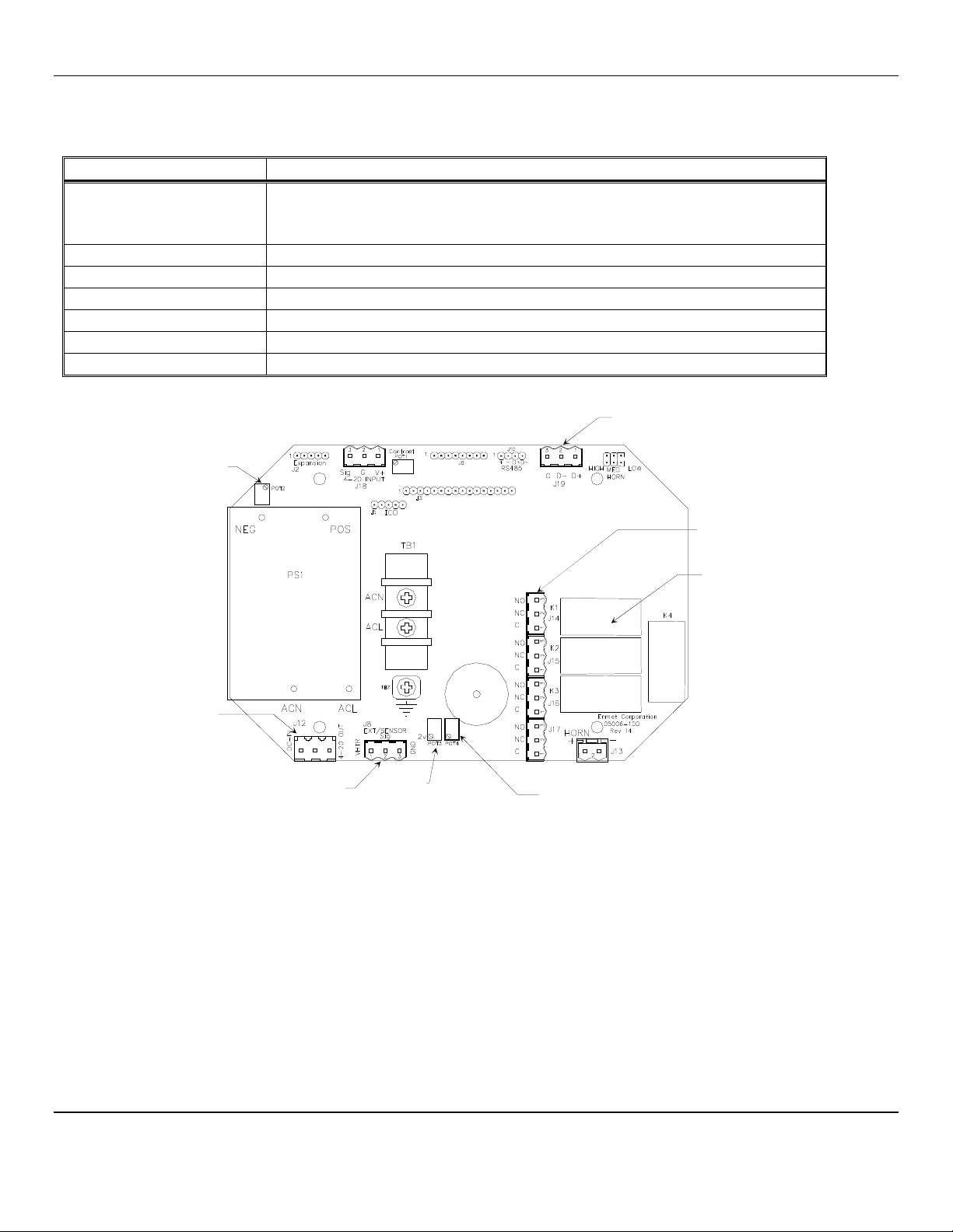
2.3 Circuit Board Features
The Display Panel is attached by a cable and is released by unscrewing the 4 screws located in the corners. After releasing the
panel, it is swung upward, exposing the interior of the enclosure. The Circuit Board is mounted at the back surface of the
enclosure interior. Features are shown in Figure 2.
Feature Description
Relay Terminals:
J14, J15, J16, J17 This group of terminals is located on the Circuit Board.
For the contacts for each of three alarm relays, and for the contacts of a fault relay.
See Section 3.3
Terminal J12 For VDC back-up power in and the 4-20 mA output. See Section 3.1.2
Sensor Terminal J8 Sensor connection, See Section 3.2
Data Terminal J19 RS-485 input/output
Potentiometer 4 Sensor heater voltage adjustment, See Section 3.2.1
Potentiometer 2 & 3 Not used in AM-5150 Do Not Adjust
Figure 2: AM-5150 Circuit Board Features
Relay Terminals
J14, J15, J16, J17
Relays
K1, K2, K3, K4
Terminal J12
DC Power In
4
-
20mA Output
RS
-
485 Input/Output
Terminal J19
Sensor Heat
er Voltage
Adjustment POT 4
POT 2
Sensor
Connection
Terminal J8
POT 3
AM-5150 ENMET Corporation
4
3.0 Installation of the AM-5150
The AM-5150 is supplied with a strain relief for a power line cord. Use this fitting or connect a conduit fitting when supplying
power to the unit.
NOTE:This control panel is NOT rated for hazardous locations. The control panel must be located in a NON-Hazardous area.
3.1 Mounting AM-5150
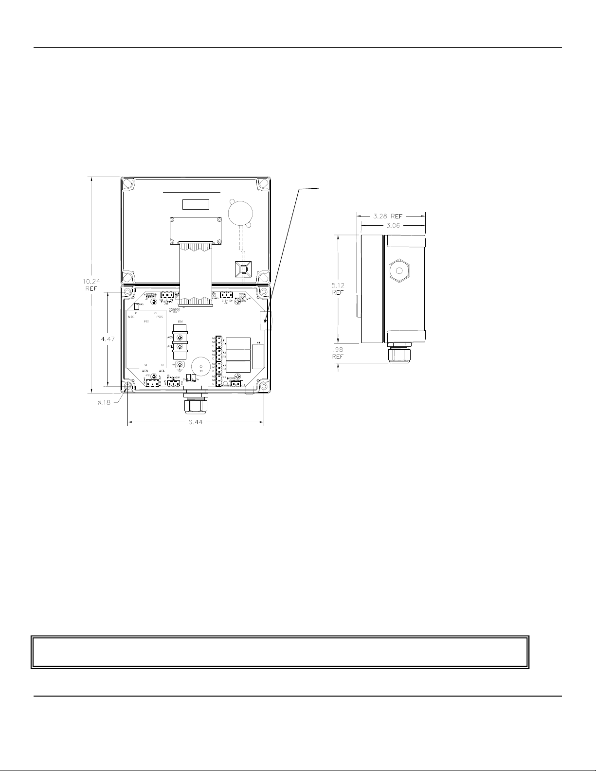
Mount the AM-5150 instrument on an appropriate vertical surface, leaving room for lid to be opened, using the mounting holes
provided. Avoid areas with excessive vibration or temperature extremes. The holes in the bottom of the enclosure are 0.18
inch in diameter and form a 6.44″x 4.47″rectangle. See Figure 3
It is recommended to use #8 drywall anchors and screws for mounting the AM-5150 to a drywall/sheetrock surface.
Dimensions are in inches.
Figure 3: Mounting AM-5150
3.1.1 Wiring the AM-5150
The electrical installation should conform to appropriate electrical codes, such as the National Electrical Code in the United
States.
W
ARNING
:
The compliance of the installation to appropriate codes is not ENMET’s responsibility.
The AM-5150 should be powered through circuit breakers provided for this purpose.
3.1.2 Power Supply
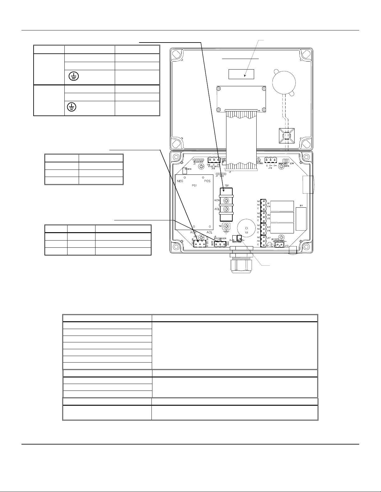
The input power can vary from 100 to 240 VAC, 50/60 Hz. Power should be connected to the Power Input Terminal TB1 and
the Ground screw. See Figure 4 for location.
For DC wiring 24VDC may be wired to J12, (J12-1)position 1 + with ground connected to (J12-2)position 2.
Upon supplying power to the AM-5150:
The green power on LED is lit.
The display backlight is lit, and instrument will step through a start-up sequence: unit serial number and software revision
may be shown on the display.
The instrument may go into alarm briefly, but the sensors stabilize quickly. If the instrument persists in alarm, acknowledge the
alarm by pressing the SELECT button. If alarm persists longer than 30 minutes, call ENMET customer service personnel.
W
ARNING
:
Continuous gas detection and alarm systems (110V
AC
/220V
AC
/ 24V
DC
/12V
DC
powered) become inoperative upon loss of
primary power. Contact factory for specifications and pricing of backup battery systems
.
Right Side View
Cover Inside View
Opened Upward
Attached to Base
Access for Sensor / Remote Sensor Wiring
AM-5150 ENMET Corporation
5
AC Power Supply Terminal: TB1
Label on PCB Function
110V
AC
TB1 ACN Neutral
TB1 ACL Line
Ground
Screw AC GND
220V
AC
TB1 ACN Neutral
Optional TB1 ACL Line
Ground
Screw AC GND
C
AUTION
: 110/220 V
AC
when applied
DC Power Supply/4-20mA
Terminal: J12
Position Function
1 + 24 V
DC
power
2 GND
3 4 - 20 mA out
Sensor Terminal: J8
Position
Function Color
1 Heater Orange
2 Signal Blue
3 Ground 2 wires, Brown & Yellow
Figure 4: Power Terminal Connections AM-5150
3.2 Sensor Location
Gases have different densities. Some are heavier than air and concentrate at the bottom of a space. Some are lighter than air
and gather at the top. Consider the density of the gas you want the sensor to detect when you install the sensor. Some
examples are given below.
Heavier than Air Gas
Sensor Location
Bottled LP (liquefied petroleum) Interior wall; 18-24" from floor.
D
O
N
OT
locate directly above or beside gas appliances (ovens,
heaters).
Avoid locating anywhere near a vent or window or near an outside
doorway.
Propane
Butane
Gasoline
Trichloroethylene
Vaporized hydrocarbons
Hydrogen sulfide
Lighter than Air Gas
S
ensor Location
Natural gas (methane) Near ceiling.
D
O
N
OT
locate directly above appliances where it is subject to
direct exposure to heat or steam.
Ammonia
Hydrogen
Same Density as Air Gas
Sensor Location
Carbon Monoxide 4-6 feet above the (generally uniform) floor.
D
O
N
OT
locate in direct air currents of windows, doors, or vents.
If you have a question involving the location of a unit or sensor, please contact your distributor or ENMET personnel. A
technician will analyze the question and recommend a location.
Sensor Heater Voltage
Adjustment POT 4
Sensor Heater Voltage Label
Cover Inside View
Opened Upward

AM-5150 ENMET Corporation
6
3.2.1 Sensor Hook-up
The MOS sensor is connected to the AM-5150 control unit with four-conductor wiring, use the correct oil tight fitting. Two
conductors supply heater voltage and heater ground for the sensor. The third and fourth conductors are signal and signal
ground wires. Size of the wire depends on the distance between the particular sensor and the control unit.
Recommended Wire Gauge
Sensor Type
Distance from Sensor to Control Unit
Recommended Wire Gauge
High Voltage:
812, 813, 826, etc.
≤
500 feet 16 AWG
501 – 800 feet 14 AWG
Longer Distances Contact ENMET Corp
Low Voltage: 109
≤
50 feet 16 AWG
Longer Distances Contact ENMET Corp
Wiring for
4
-
wire Terminal
Sensors
Position Function Wire Color
1 Heater Orange
2 Signal Blue
3 Heater Ground Brown
4 Signal Ground Yellow
Wiring for 3-wire Terminal Sensors
Position Function Wire Color
1 Heater Orange
2 Signal Blue
3 Heater Ground Brown
Wire Nut Signal Ground Yellow
N
OTE:The yellow signal wire is not connected to the
terminal block, use supplied wire nut.
Figure 5: Internal View of Sensor Wiring
Wire length between the AM-5150 and the sensor greater then 100ft will require that the sensor heater voltage be reset. After
you mount and install the AM-5150 and Sensor, you must verify the sensor heater voltage. Use position 2 and 3 to measure
heater voltage.
Locate the sensor heater voltage table label inside the instrument, see Figure 4. Measure the sensor heater voltage at the
sensor, see Figure 5 and adjust the heater adjustment POT 4 until required voltage is reached, see Figure 4.
Optional
Splash Shield
Sensor Wiring Terminal*
The 4
th
(yellow) wire is not
connected to the terminal
block, use supplied wire nut
Optional
Splash Shield
AM-5150 ENMET Corporation
7
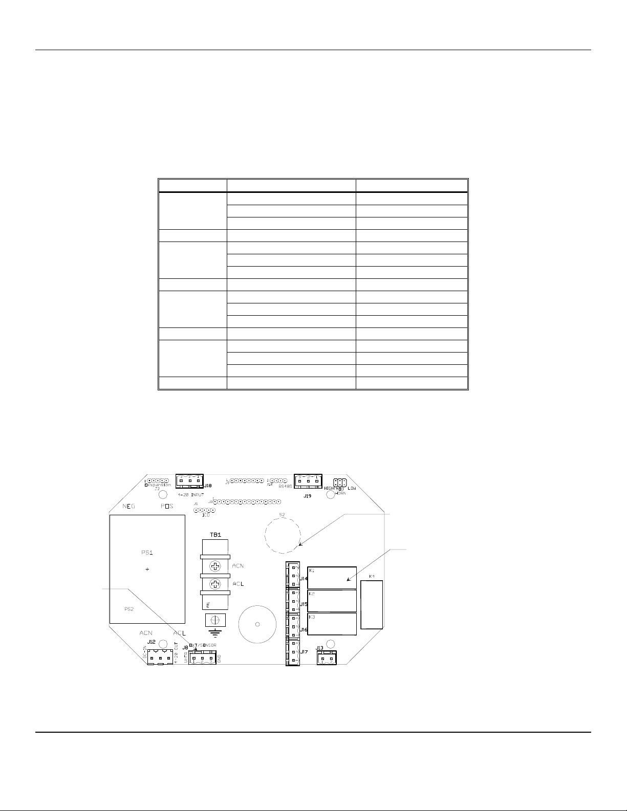
3.3 Relay Contacts
Relay contacts are available for each alarm; these are SPDT, rated at 10Amp at 110VAC, and may be latching or non-latching
as required by the application.
They are accessed on the terminals next to each relay see Figure 6. The contact positions are noted on the circuit board next to
each terminal.
The following table is for the relays in their un-energized state. This is also the alarm condition state. Non-failsafe configured
relays in the alarm state, are the reverse of the PC board labeling. Note that the Fault(FLT) relay cannot be set to operate in a
Non-Failsafe mode. Please see Table 1 below:
T
ABLE
1
:
R
ELAY
F
AILSAFE
S
ETTINGS
Alarm
Position
Alarm 1 J14 (K1)Relay 1 - NO Normally Open
J14 (K1)Relay 1 - NC Normally Closed
J14 (K1)Relay 1 - COM Common
Alarm 2 J15 (K2)Relay 2 - NO Normally Open
J15 (K2)Relay 2 - NC Normally Closed
J15 (K2)Relay 2 - COM Common
Alarm 3 J16 (K3)Relay 3 - NO Normally Open
J16 (K3)Relay 3 - NC Normally Closed
J16 (K3)Relay 3 - COM Common
Fault Alarm J17 (K4)Relay 4 - NO Normally Open
J17 (K4)Relay 4 - NC Normally Closed
J17 (K4)Relay 4 - COM Common
These relay contacts can be used to operate auxiliary alarms or other functions. The relay contacts are DRY, power must be
supplied. It is recommended that power for auxiliary equipment be supplied from an independent power source separate form
the AM-5150. Use the existing hole in the enclosure for wire to enter and exit and use appropriate cable fittings. Wiring
should be grouped together, VAC wires should be separated for VDC wires.
Figure 6: Relay Terminal Connections AM-5150
Relay Terminals
J14, J15, J16, J17
Relays
K1, K2, K3, K4
Sensor Terminal J8
AM-5150 ENMET Corporation
8
4.0 Operation
When the AM-5150 is installed as described in Section 3, and in clean air, the POWER green LED is on, the display is lit and
the information on the display is measurement of the target detected by the AM-5150.The red alarm and fault LEDs are not lit.
4.1 Start Up AM-5150
When the AM-5150 is first powered up, it goes through a series of momentary screens, which identify the instrument model
number, serial number and software revision. After all of the momentary screens have been displayed, the instrument arrives at
the Main Gas Display showing the gas concentration and unit of measurement, ppm or %LEL.
Depending on transmitter configuration and calibration condition, the furthest right character in the display may flash a letter
indicating the instrument status. See the Section 4.1.1 below
4.1.1 Typical Start Up
When power is supplied to the AM-5150, the instrument will display the following sequence of information:
Typical start up sequence of information displayed.
Example of Typical Start Up Display Function
The instrument: Model
AM
-
5150
Example for reference only
The instrument: Serial Number
Example for reference only
The instrument: Software Revision
IF the right most character is a flashing
W
The instrument is in Warm-up mode
This should last about 1 minute
The Signal Output is held at 4mA during warm-up
IF the right most character is a flashing
C
The instrument has failed Calibration
The last good calibration values are retained, but the sensor
may not be responsive to gas
A new Calibration should be performed As Soon As Possible
OR The instrument: Normal Display Mode
Measurement of the target gas
The instrument: in Purge Mode Display
Optional feature, not required in all instruments
The instrument: in Recovery Mode Display
Optional feature, associated with purge mode
N
OTE
:
Software revision may cause variations of display output.
Prolonged storage of the AM-5150-MOS may result in some contamination of the sensor. Following start up, if the display
reads above 000 a sensor purge function should be preformed.
Sensor Purge: A sensor purge is performed to clean the MOS sensor (Metal Oxide Sensor) of molecules that may have settled
on the sensor.
N
OTE
:
Not all instruments are equipped with or require the Purge feature. To determine if the purge feature is operational.
Press and hold the SELECT switch, 3 to 5 seconds, if purge feature is operational 0ppP appears in the display.
If the AM-5150-MOS is equipped with the purge feature, the display will alternate between 0ppm and 0ppP and the green
Power/Fault LED will flash. In approximately 2 minutes the purge function will be completed and the display will, alternate
between 0ppm and 0ppR indicating the instrument is in recovery mode. Recovery mode lasts approximately 5 minutes.
When the purge cycle is complete, the display will become stable at 0ppm and the green Power/Fault LED will stop flashing.
AM
-
5150
311
-
20
S/W 6.6F
0ppW
0ppC
0ppm
0LEL
0ppm
0ppP
0ppm
0ppR
AM-5150 ENMET Corporation
9
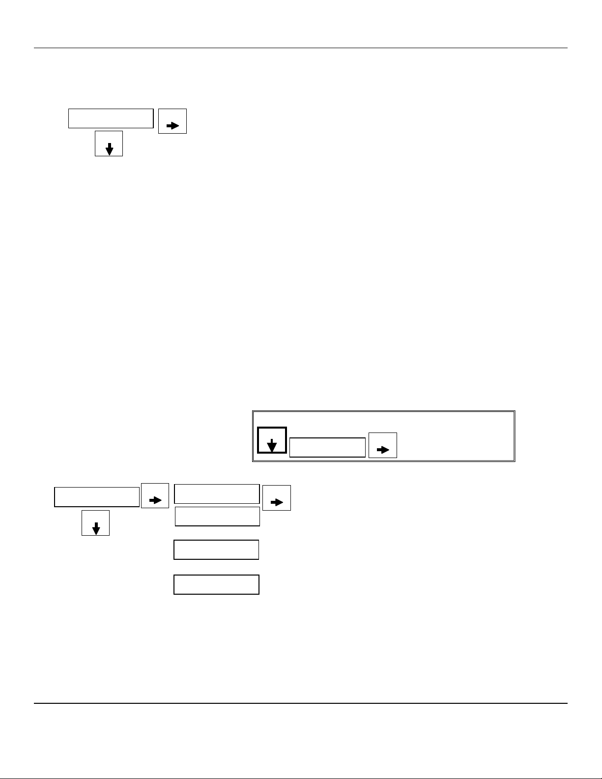
4.2 Normal Display Mode
When the AM-5150 is installed as described in section 3, and in clean air, the POWER green LED is on, the display is lit and
the information on the display in measurement units of ppm or %LEL detected by the AM-5150.The red alarm and fault LEDs
are not lit.
To advance through displays of operational information press the MENU button.
N
OTE
:
Software revision may cause variations of display output.
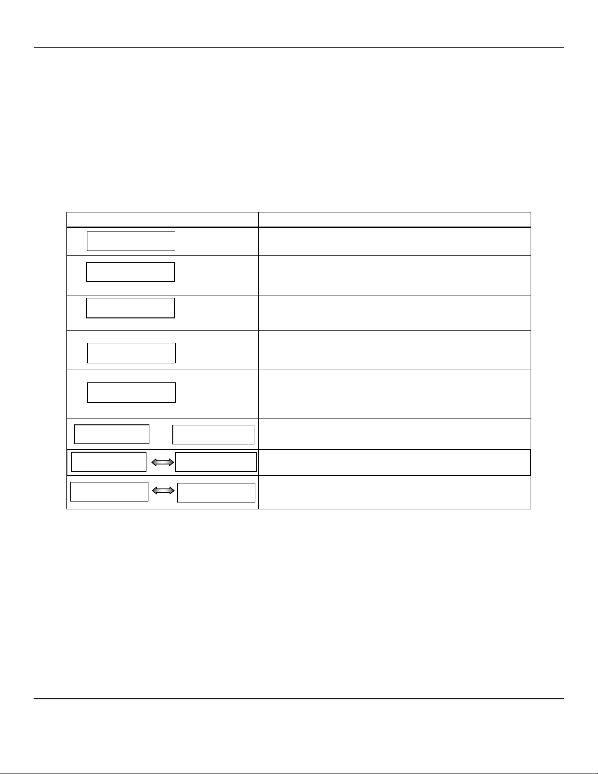
See sequence of operational information below:
Display Measurement of the target gas
Press MENU button
Display indicates Alarm 1 Set point
Press MENU button
Display indicates Alarm 2 Set point
Press MENU button
Press SELECT button
To temporally disable audio
alarm, see Section 4.2.1
Display indicates Alarm 3 Set point
Press MENU button
Display indicates mA Span range
(Full Scale)
Press MENU button
Display returns to gas measurent
Operational Display Flow Chart
4.2.1 Alarm Conditions AM-5150
There are three alarm set points available. These alarm points are normally set at established safety levels, such as the OSHA
Permissible Exposure Limit (PEL) for toxic gases or recognized standards below the Lower Explosive Limit for combustible
gases.
These alarm set points can be changed within limits; see the maintenance section of this manual for the procedure.
If the gas concentration increases above that of the alarm set point, the associated red LED is lit, the associated relay changes
state, and the audio alarm is activated.
Pressing the SELECT button can temporally disable the Audio Alarm. The horn will be disabled for about five minutes. If a
second alarm condition occurs during this time the horn will re-activate. If the alarm condition(s) have ended during this time
the horn will not re-activate.
0ppm
A1: 05
S
ELECT
S
ELECT
MENU
MENU
A2: 10
S
ELECT
MENU
A3: 20
S
ELECT
MENU
mA: 50
S
ELECT
MENU

AM-5150 ENMET Corporation
10
5.0 Maintenance
The AM-5150 maintenance menus that are accessed by pressing the MENU button and SELECT button as described in the
maintenance menu section.
5.1 Maintenance Menus
Pushbutton switches control the MENU and SELECT functions. The MENU and SELECT button locations are indicated on the
display panel, see Figure 1. The MENU button is used to display the various menu options and make incremental changes to
numbers such as alarm points, calibrations gas, etc. The SELECT button is used to select that option, set zero or span digit.
To enter the maintenance menu press and hold the MENU button for 2 to 4 seconds
Table 2 indicates the maintenance menu sequence see Figure 7 for a detailed maintenance menu flow chart.
CAUTION:Do Not Attempt A Span Procedure Without Calibration Gas Applied to The Sensor; if this is done, the instrument is
forced into a calibration fault mode.
N
OTE
:
Software revision may cause variations of display output.
T
ABLE
2:
AM-5150
M
AINTENANCE
M
ENUS
S
EQUENCE
Example of Display Function
Normal Display Mode Measurement of CO
Press and hold the MENU button for 2 – 4 seconds to enter the Maintenance Menu
The Power/Fault LED will flash Green – Red to indicate the AM-5150 is in Maintenance Mode
To exit the maintenance Menu and return to the
Normal Display Mode:
If intended function Press SELECT button
Press the MENU button to advance to the Zero procedure
For adjusting Zero:
If intended function Press SELECT button
Press the MENU button to advance to the Span procedure
For adjusting the Span:
If intended function Press SELECT button
Press the MENU button to advance to each Alarm set point procedures
For adjusting the Alarm 1, 2 and 3 set points:
If Intended function Press SELECT button
Press the MENU button to advance the mA Span set point procedure
For adjusting the mA Span set point:
If intended function Press SELECT button
Pressing the MENU button without pressing the SELECT button will allow you to cycle through the menu options.
You must Press the SELECT button in order to initiate the desired operation.
5ppm
Exit
Zero
Span
mA Span
Alarm1
Alarm2
Alarm3
AM-5150 ENMET Corporation
11
N
OTE
:
Software revision may cause variations of display output.
Normal Gas Display
F
IGURE
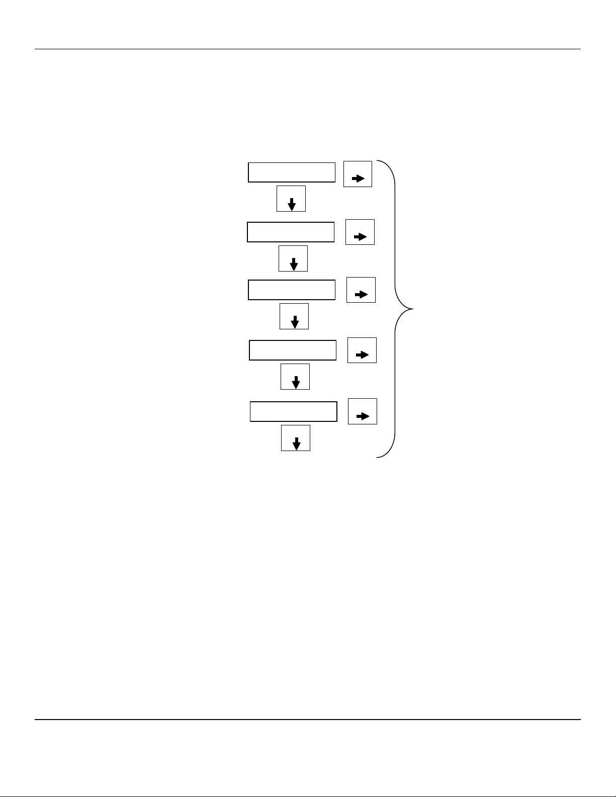
7:
AM-5150 Maintenance Menu Flow Chart
5ppm
MENU
Press and HOLD the MENU button for 2 – 4 seconds to enter the Maintenance Menus
Exit
S
ELECT
Press the SELECT button to return to the Normal Gas Display. See Section 5.2.1
MENU
Press the MENU button to cycle through Maintenance Menus
OR
OR
MENU
PV: 0
20
Apply
Cal Gas until signal value becomes stable
(about 1 to 4 minutes) See Figure 8
Press SELECT to enter the cal signal:
If cal is good display will indicate OK or Same
If cal is not within preset “range” display will
indicate Bad Sens
Cal OK
Same mV
Bad Sens
Span
S
ELECT
S
ELECT
S
ELECT
You can Press and
H
OLD the
S
ELECT button to
change the Calibration Gas Level
See Section 5.2.3
Alarm1
MENU
Alarm2
MENU
Alarm3
S
ELECT
S
ELECT
S
ELECT
20
5
5
10
10
To change Alarm set points:
Press Menu button until Alarm to be changed is displayed
Press Select button to display the set point
The M
ENU
button changes digit indicated by underscore
cursor
The S
ELECT
button locks underscored digit and moves to
next digit
If change is not within range display returns to first digit
If change is within range display moves to next menu
See Section 5.2.4
MENU
mA Span
MENU
S
ELECT
0050
To change mA Span set point:
Press Menu button until mA Span is displayed
Press Select button to display the set point
The M
ENU
button changes digit indicated by underscore cursor
The S
ELECT
button locks underscored digit and moves to next digit
See Section 5.2.5
To
return to Normal Gas Display:
Press MENU button until EXIT is displayed
Then press SELECT button
OR
Zero
Cal OK
If
the Zero signal is not within Preset Specs the AM-5150 will
display Bad ZERO
S
ELECT
MENU
Bad ZERO
If
the Zero signal is within Preset Specs the AM-
5150 will display
Cal OK, See Section 5.2.2
PV:
0
S
ELECT
Press the SELECT button to initiate Zero adjustment
AM-5150 ENMET Corporation
12
5.2 Calibration of the AM-5150
Sensor Purge: Prior to calibration some MOS(Metal Oxide Sensor) sensor should be purged. A sensor purge is performed to
clean the MOS sensor of molecules that may have settled on the sensor.
Press and hold the SELECT switch, 3 to 5 seconds, if the purge feature is operational 0ppP appears in the display. If the AM-
5150-MOS is equipped with the purge feature, the display will alternate between 0ppm and 0ppP and the green Power/Fault
LED will flash. Example of purge display
In approximately 2 minutes the purge function will be completed and the display will, alternate between 0ppm and 0ppR
indicating the instrument is in recovery mode. Recovery mode lasts approximately 5 minutes.
Example of purge recovery display
When the purge cycle is complete, the display will become stable at 0ppm and the green Power/Fault LED will stop flashing.
Calibration is the process of setting the instrument up to read accurately when exposed to the target gas. The Zero function sets
the clean air reference point and the Span function sets the sensitivity of the instrument.
Initial Calibration: Wait at least 3 – 4 hours after initially supplying power to the AM-5150 instrument before initial
calibration, overnight is preferred. The AM-5150 has been pre-calibrated at the factory, and initial field calibration should
result in only fine-tuning to circuit, as well as a way to check that installation is successful. It is not necessary to open the
enclosure to make adjustment. The calibration functions are operated with pushbuttons from outside the enclosure through the
MENU and SELECT switches.
Calibration Zero and Span functions are two separate procedures. They operate independently of each other. It is
recommended that the Zero procedure be done prior to the Span procedure.
ENMET Corporation recommends at least quarterly calibration of the AM-5150 instrument.
Calibration equipment is available from ENMET Corporation to calibrate the AM-5150 instrument.
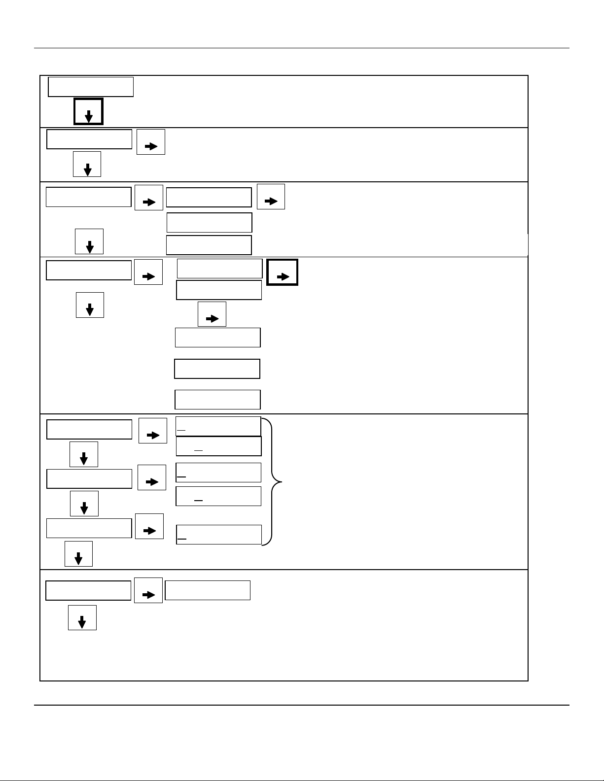
•Calibration adapter, a length of tubing with a regulator for the gas cylinder on one end, and a calibration cup to connect to
the sensor of the AM-5150 on the other.
•Gas cylinder, Zero gas 20.9% oxygen or Span gas, factory determined, varies by intent.
Generally, a cylinder of 20.9% Oxygen is used to provide a Zero point or fresh air reference for the calibration.
N
OTE
:
Software revision may cause variations of display output.
Figure 8: Calibration Adapter
Menu
Select
Sensor
Enclosure
Sensor
Gas Cylinder
Regulator
Humidifier
Calibration Cup
To Cal Cup
Top View of Humidifier
To Regulator
0ppm
0ppR
0ppm
0ppP
AM-5150 ENMET Corporation
13
5.2.1 Exit Maintenance Menu
Exit maintenance, by pressing the Exit appears on the display. Press the SELECT button to return to the instrument Normal Gas
Display.
Example of Exit menu:
5.2.2 Zero Adjust
The ZERO function must be performed by exposing the AM-5150 instrument to clean fresh air. If the air at the sensor is in
question, use a cylinder of 20.9% oxygen to provide a clean air reference.
Enter the maintenance menu by pressing and holding MENU button for 2 to 4 seconds. See Figure 7, AM-5150 Maintenance
Menu flow chart.
After entering the maintenance menu, Press the MENU button until the Zero menu is displayed.
Press the SELECT button to perform a Zero.
The display will alternate between Zero and PV: To abort Zero function press and hold MENU button for 3 – 4 seconds,
Abort? will appear, press SELECT button to return to Zero.
Press the SELECT button to initiate a Zero adjustment.
An auto detect sequence is initiated. After 15 seconds, the AM-5150 will monitor the zero reading for stability.
If the reading stabilizes, within the pre-programmed perimeters, an automatic zero adjustment will be made.
Cal OK appears on the display and in 1 – 2 seconds, display will change to Span.
If you wish to Span the sensor press the SELECT button you are now ready to apply gas. Proceed to gas span step 2
If you wish to Exit the maintenance menu, press MENU button until Exit is displayed, then press SELECT button to return to
the instrument Normal Gas Display
If the reading does not stabilize, within 255 seconds, the procedure will be aborted. Sensor is outside of safe parameters to
be zeroed, the display will read Bad Zero. Repeat Section 5.2.2 Zero Adjust making sure to use a Zero gas of 20.9%
Oxygen. ENMET part number 03296-209.
Example of Zero adjustment display:
N
OTE
:
Software revision may cause variations of display output.
Exit
S
ELECT
Press the SELECT button to return to the Normal Gas Display.
MENU
Press the MENU button to cycle through Maintenance Menus
OR
Zero
Cal OK
If
the Zero signal is not within Preset Specs the AM-5150
will display Bad Zero and return to Zero menu
S
ELECT
MENU
Bad ZERO
If
the Zero signal is within Preset Specs the AM-5150 will
display Cal OK momentarily then advance to Span menu
PV:
0
S
ELECT
Press the SELECT button to force Zero adjustment
Zero
Note: You can Press and
H
OLD
the
M
ENU
button to abort Zero
When Abort? appears press S
ELECT
button to
return to Zero menu
A ort
?
S
ELECT
MENU

AM-5150 ENMET Corporation
14
5.2.3 Gas Span
It is recommended that the Zero Function be performed first.
Do not perform a calibration unless span gas is applied to sensor. Calibration can be aborted by pressing and holding the MENU
button for 3 – 4 seconds.
Enter the maintenance menu. See Figure 7, AM-5150 Maintenance Menu flow chart.
1. Press the MENU button until Span display.
2. Press the SELECT button to perform a Span procedure.
The display will alternate between the calibration gas concentration (Example: Cal 20) and a signal level (PV).
•To Abort calibration press and Hold MENU button for 3 – 4 seconds, “Abort?” will appear, press SELECT button to return
to Span.
•To change calibration gas level to be used, press and Hold SELECT button for 3 – 4 seconds, use menu button to change
digit and select button to move to next digit.
3. Attach the associated calibration gas cylinder to the calibration adapter. See Figure 8calibration adapter.
4. Open the valve to apply the calibration gas to the sensor.
An auto detect sequence is initiated after 30 seconds, the AM-5150 will monitor the cal reading for stability.
5. Watch for the signal level to stabilize. This should take about 1 – 4 minutes.
6. Once the signal level has stabilized,
If the Span is successful, Cal OK appears momentarily, then will advance to Alarm1 menu.
To exit cal, press MENU button until Exit appears and press SELECT button
If the sensor is outside of acceptable parameters, Bad Span is displayed.
If the sensor did not respond, an incompatible span gas was applied and the sensor did not respond at all,
Same mV is displayed then will return to Span.
If calibration is not successful, it is suggested that calibration be attempted again in 30-60 minutes.
If the sensor will not calibrate See Section 5.3 for sensor replacement.
7. Remove the calibration gas.
8. Press the MENU button to advance to Exit menu or desired menu.
N
OTE
:
Software revision may cause variations of display output.
Example of Calibration Display:
NOTE:
To abort calibration. Press and H
OLD
the M
ENU
button to abort Calibration
When “Abort?” appears press S
ELECT
button to advance to desired menu
A ort?
S
ELECT
MENU
OR
MENU
PV: 0
20
Apply
Cal Gas until signal value becomes stable
(about 1 to 4 minutes) See Figure 8 Calibration Adapter
When cal signal is stable AM-5150 will automatically update:
If cal is good display will indicate OK or Same and advance to
Alarm1
If
cal is not within preset “range” display will indicate Bad Sens
or Same mV The AM-5150 will return to the Span Menu
To exit press MENU button until Exit appears and press SELECT
Cal OK
Span
S
ELECT
S
ELECT
PV: 0
Same mV
Bad Sens
NOTE:
To change calibration gas level. Press and H
OLD
the S
ELECT
button to change the Calibration Gas Level
-Use the M
ENU
button to change digits
-Use the S
ELECT
button to move to next digit
S
ELECT
20

AM-5150 ENMET Corporation
15
5.2.4 Alarm Set Points
The AM-5150 has three alarm set points set at the factory. These alarm points are normally set at established safety levels.
Alarm set points can be changed within limits.
To change any of the three alarm points:
Enter the maintenance menu as shown in Figure 7 AM-5150 Maintenance Menu flow chart.
1. Press the MENU button until to display Alarm1 is displayed.
2. Press the SELECT button to initiate alarm set point change
3. Press the MENU button to change the digit indicated by the underscore cursor
4. Press the SELECT button to move the cursor to the next digit
When last digit is entered the AM-5150 will advance to the next menu
5. Press the MENU button to advance to the next menu
NOTE: Alarms 2 and 3 can not be set below the Alarm 1 setting.
Example of Alarm Set Point menus:
N
OTE
:
Software revision may cause variations of display output.
5.2.5 mA Span Set
The AM-5150 4-20mA span range is set at the factory, normally to the full scale of the measurement and can be changed
within limits.
To change the span range:
Enter the maintenance menu as shown in Figure 7 AM-5150 Maintenance Menu flow chart.
1. Press the MENU button until to display Span is displayed.
2. Press the SELECT button to initiate the mA Span menu
3. Press the MENU button to change the digit indicated by the underscore cursor
4. Press the SELECT button to move the cursor to the next digit
When last digit is entered the AM-5150 will advance to the next menu
5. Press the MENU button to advance to the next menu
Example of mA Span menu:
Default mA Span
4mA 20mA
0 ppm 200 ppm
Alarm1
MENU
Alarm2
MENU
Alarm3
S
ELECT
S
ELECT
S
ELECT
20
5
5
10
10
To change Alarm set points:
Press Menu button until Alarm to be changed is displayed
Press Select button to display the set point
The M
ENU
button changes digit indicated by underscore
cursor
The S
ELECT
button locks underscored digit and moves to
next digit
If change is not within range display returns to previous digit
If change is within range display moves to next menu
MENU
mA Span
MENU
S
ELECT
0200
To change mA Span set points:
Press Menu button until mA Span is displayed
Press Select button to display the set point
The M
ENU
button changes digit indicated by underscore cursor
The S
ELECT
button locks underscored digit and moves to next digit
AM-5150 ENMET Corporation
16
5.3 Sensor Replacement
The MOS sensor is durable, it can be purged of contaminants by operating in PURGE for a sufficient length of time and at
regular intervals.
Gross contamination usually occurs during unavoidable misuse. Close exposure to an open gas flame, submersion of the sensor
in a liquid, or continuous exposure to heavy concentrations of industrial vapors will grossly contaminate a sensor. A grossly
contaminated sensor causes a continuous alarm.
If a sensor fails to calibrate, replace it.
PROCEDURE:
W
ARNING
:
Power must be removed from the AM-5150 before this or any internal procedure. Failure to do so may cause
damage to equipment, bodily injury or death.
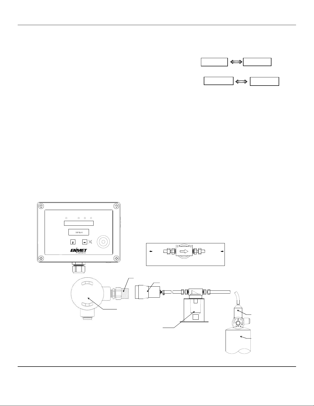
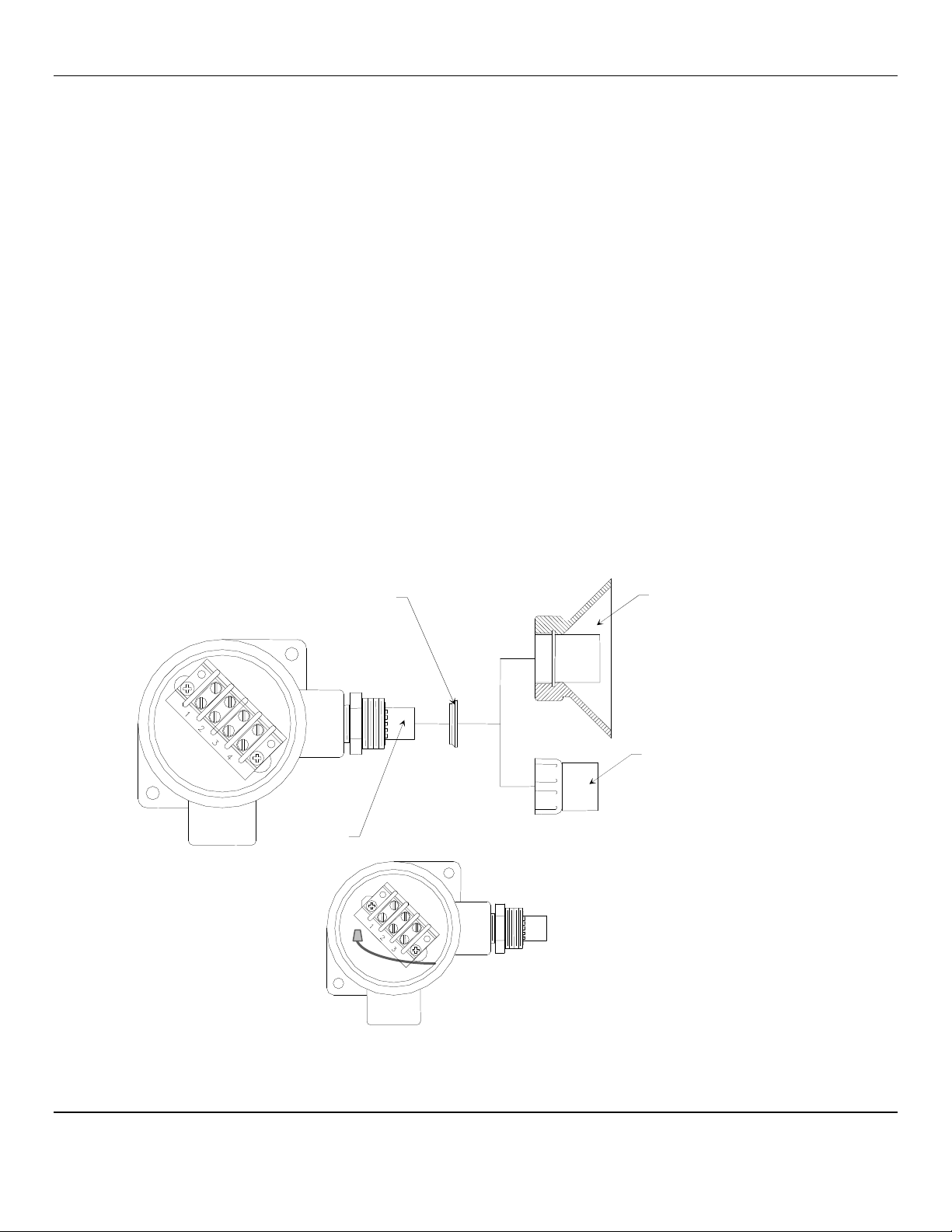
1. Obtain a new sensor assembly. Make sure the sensor type is identical to your original sensor
Sensor marking is on side of sensor see Figure 9
(Example: 813-4 the first 3 digits are sensor ID the 4 digit indicates a 4-wire sensor).
2. Disconnect the instrument for power.
3. Disconnect the orange, brown, blue and yellow sensor wires.
4. Unscrew the assembly from the sensor enclosure.
5. Remove the bad sensor.
6. Replace with the new sensor and reconnect the wires (See Section 3.2.1).
NOTE: The user must perform the four color-coded wiring attachments when replacing the sensor. If the yellow signal wire
is not connected to the terminal block, use supplied wire nut.
7. Reconnect the instrument to power and verify sensor heater voltage. (See Section 3.2.1)
8. Recalibrate the instrument (See Section 5.3.1).
Figure 9: AM-5150 Sensor Replacement
After the new sensor assembly has been installed, it is suggested to allow the sensor to stabilize for at least 3 – 4 hours,
preferably over night.
Sensor
Spacer Ring
*Replace facing direction as shown
Optional Splash Shield
Standard Sensor Shield
View of 3-wire Terminal
View of 4-wire Terminal

AM-5150 ENMET Corporation
17
5.3.1 Sensor Replacement Calibration
Sensor Purge: Prior to calibration some MOS(Metal Oxide Sensor) sensor should be purged. A sensor purge is preformed to
clean the MOS sensor of molecules that may have settled on the sensor.
Press and hold the SELECT switch, 3 to 5 seconds, if the purge feature is operational 0ppP appears in the display. If the AM-
5150-MOS is equipped with the purge feature, the display will alternate between 0ppm and 0ppP and the green Power/Fault
LED will flash. Example of purge display
In approximately 2 minutes the purge function will be completed and the display will, alternate between 0ppm and 0ppR
indicating the instrument is in recovery mode. Recovery mode lasts approximately 5 minutes.
Example of purge recovery display
When the purge cycle is complete, the display will become stable at 0ppm and the green Power/Fault LED will stop flashing.
Calibration is the process of setting the instrument up to read accurately when exposed to the target gas. The Zero function sets
the clean air reference point and the Span function sets the sensitivity of the instrument.
Initial Calibration: Wait at least 3 – 4 hours after initially supplying power to the AM-5150 instrument before initial
calibration, overnight is preferred. The AM-5150 has been pre-calibrated at the factory, and initial field calibration should
result in only fine-tuning to circuit, as well as a way to check that installation is successful. It is not necessary to open the
enclosure to make adjustment. The calibration functions are operated with pushbuttons from outside the enclosure through the
MENU and SELECT switches.
Calibration Zero and Span functions are two separate procedures. They operate independently of each other. It is
recommended that the Zero procedure be done prior to the Span procedure.
ENMET Corporation recommends at least quarterly calibration of the AM-5150 instrument.
Calibration equipment is available from ENMET Corporation to calibrate the AM-5150 instrument.
•Calibration adapter, a length of tubing with a regulator for the gas cylinder on one end, and a calibration cup to connect to
the sensor of the AM-5150 on the other.
•Gas cylinder, Zero gas 20.9% oxygen or Span gas, factory determined, varies by intent.
Generally, a cylinder of 20.9% Oxygen is used to provide a Zero point or fresh air reference for the calibration.
N
OTE
:
Software revision may cause variations of display output.
After entering the Maintenance menu, press and hold the MENU button for 2-4 seconds while viewing the Zero menu.
After 2-4 seconds, an F will appear on the far right hand side of the display. The F indicates that the instrument is in Factory
mode.
Perform the calibration Zero and Span procedures as outlined in Section 5.2. Be sure that the F is present when selecting the
Zero and Span functions.
The Factory calibration sets a calibration window for future standard instrument calibrations.
0ppm
0ppR
0ppm
0ppP

AM-5150 ENMET Corporation
18
6.0 Accessory and Replacement Parts
ENMET accessory part numbers:
Description of Part
Part Number
Sensor Marking, 109-4 03034-109
Sensor Marking, 812-4 03034-812
Sensor Marking, 813-4 03034-813
Sensor Marking, 018-4 03034-018
Sensor Marking, 019-4 03034-019
Sensor Marking, 821-4 03034-821
Sensor Marking, 830-4 03034-830
Sensor Marking, 832-4 03034-832
Zero Gas, 20.9% O2, 17 liter 03296-209
Span Gas
Cylinder of Calibration Gas Contact ENMET for part number
of target gas for each instrument.
See note below.
NOTE: The gases should be identical, or equivalent (correlation gas) to those used to initially calibrate the unit, unless you want
to recalibrate to a new gas or different concentration. In addition, calibration gases must be in a background of air; do
not use gases with an inert gas background (such as nitrogen or argon).
7.0 Technical Data and Specifications
Electrical Power
15 Amp fused branch circuit
100-240 V
AC
0.45A, 50/60 Hz
0.6A, 24V
DC
Storage and Tr
ansport
Temperature: -20°to +60°C (-4°to +140°F)
preferred 0°to +20°C (32°to 68°F)
Relative Humidity 10-99% RH, non-condensing
Atmospheric Pressure 20 to 36 inHg (68 to 133 kPa)
Operation
Temperature: -15°to +40°C (5°to +104°F)
Relative Humidity 10-99% RH, non-condensing
Atmospheric Pressure 20 to 36 inHg (68 to 133 kPa)
Mechanical
Dimensions: 7.1 x 5.1 x 3 in(180x130x75mm)
Weight: 2 lbs (0.9 kg)
Material: Polycarbonate
Strain relief: 3-6.5mm OD
Outputs
Relays: SPDT
Resistive Load Inductive Load
10A at 110 V
AC
7.5A at 110 V
AC
10A at 30 V
DC
5A at 30 V
DC
Analog: 4-20mA
Digital: RS-485-modbus
Audio: 105 dB at 30cm/12in
NOTE:All specifications stated in this manual may change without notice.
Table of contents
Other ENMET Measuring Instrument manuals

ENMET
ENMET Formaldemeter htV-m User manual

ENMET
ENMET MED AIR 2000 User manual

ENMET
ENMET Recon IS User manual

ENMET
ENMET ISA-M Manual

ENMET
ENMET GSM-60 User manual

ENMET
ENMET ISA-300RAL User manual

ENMET
ENMET Recon/NH3-B User manual

ENMET
ENMET ISA-40 Series User manual

ENMET
ENMET ISA-60M User manual

ENMET
ENMET MedAir 2200 User manual


Popular Measuring Instrument manuals by other brands

Svantek
Svantek SVAN 971 user manual

Fluke Calibration
Fluke Calibration 525B Getting started guide

Pentax
Pentax Honeywell 1/21 Degree Spotmeter operating manual

PCB Piezotronics
PCB Piezotronics IMI SENSORS M629A31 Installation and operating manual

sauermann
sauermann CTV 110 quick start guide

Pentair
Pentair HAFFMANS 006.625 instruction manual


