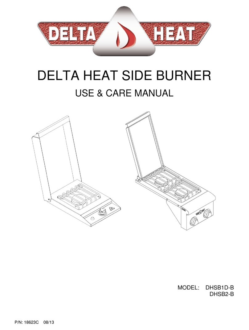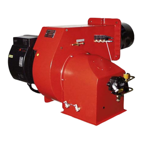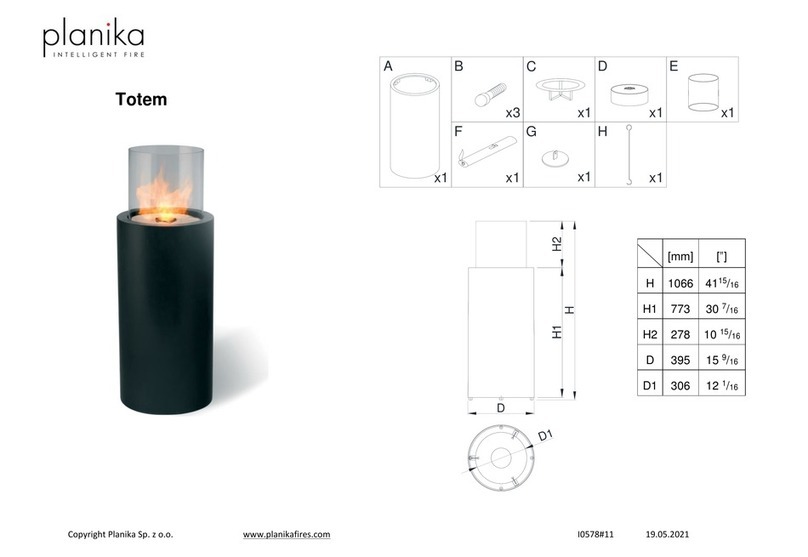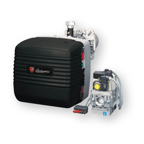
1 or 2 BURNER GAS STOVE
Class 1
Destination countries Pressure (mbar) Category
BE - CH - ES - FR - GB - GR - IE - IS - IT - LU - PT 28 - 30/37 13+
AT - DE - DK - FI - GR - NL - NO - SE - NZ 30 13 B/P
AT - CH - DE - LU 50 13 B/P
I - INSTALLATION AND MAINTENANCE CONDITIONS
This appliance is not connected to an exhaustion stroke: it has to be installed and connected in compliance with the relevant
Installation Rules. Especially respect the Regulations concerning aeration.
- The minimum air inlet necessary to a proper combustion is 2 m³/h per kW power.
- Horizontal distance between the appliance and the adjacent walls shall not be less than 90 mm.
Installation and maintenance of this appliance have to be carried out by a skilled person in accordance with the relevant
regulations, in particular:
- The User has to comply with Technical and Safety Rules prescriptions concerning use of inflammable gas and liquefied
hydrocarbons in houses and outbuildings, stipulating that no unit should be installed in any room unless:
• a sucient air inlet and outlet. • a window with a minimum opening space of 0,40m²
• a minimum volume of 8m³ • a minimum height of 0,30m from the ground are provided
- Sanitary regulations
Gas installations on board:
• Guideline 94/25/CE from European Parliament and Council dated June 16th, 1994
• ISO 10239 • ISO/DIS 9094
WARNING: When operated, naked flame appliances consume oxygen and reject exhaust materials. Ventilation is necessary
when appliances are working. Open the Ventilation holes designed for this purpose when operating cooker. Never use your
cooking appliance to warm up the living space. Never obstruct the openings designed for Ventilation (ISO/DIS 10239.3).
II - INSTALLATION OF THE UNIT
The Stove is designed to be free Standing on a piece of furniture that can resist without damage to a permanent temperature
of 90°C. Easily flammable supports must be avoided.
It is mandatory to leave a space of 90 mm minimum behind the rear edge of the Stove and a space of 50 mm between sides
of the Stove and adjacent vertical parts in order to limit increase in temperature.
INSTALLATION ON GIMBALS (drawing 1)
a. Fit the gimbals supports aand bon working surface ( see drawing 2 )
b. Fit the gimbals cand don body ethanks to screws f, washers gand nuts h(be careful with direction of cand d, the
axis of gimbals must be located outwards).
c. Place the whole on supports aand bputting the gimbals axis into openings
d. Possibility of locking the System with key i.
III - CONNECTION: suitable for marine use
Pays de destination Pression detendeur
Specifique Marine
ENOQUIP
BE - CH - ES - FR - GB - GR - IE - IS -IT - LU - PT 28 - 30/37 mbar (FR) ref.: EG3007
AT - DE - DK - FI - GR - NL - NO - SE - NZ 30 mbar (DE)ref.:EG3016
AT - CH - DE - LU 50 mbar (DE) ref. : EG3015
Installation:
Any connection to the gas supply has to be made with tight mechanical connections or with normalised connections.
NOTA: An optional gas connection kit can be supplied. „ENOQUIP“ includes:
a regulator Special for boats, a 600 mm flexible tube, a shut-o valve with its sticker, a 800 mm
flexible tube, nozzle for Ø 8 mm copper tube.
Setting-up : Regulator and flexible tube
• Special „boat“ regulator. „Shall not be used in a closed room“.
• Always make sure that the rubber seal at the regulator inlet connection is properly set and in good shape.
• Screw and tighten the regulator wing-nut on the gas cylinder or on the Special tap fitted on 3 Kg gas cylinders or on the
„CLIP-ON“ device for 6 Kg gas cylinders.
• A complete check-up of the whole installation has to be carried out punctually.
• In the case of any deterioration, „regulator, rubber tube and tap“ have to be replaced.
• To ensure a correct setting-up, avoid to twist or to curve the rubber tube.


