EnOcean TCM 515J User manual

USER MANUAL
TCM 515 / TCM 515U / TCM 515J –ENOCEAN TRANSCEIVER GATEWAY MODULE
© 2023 EnOcean | www.enocean.com F-710-017, V1.0 TCM 515 User Manual | v1.21 | July 2023 | Page 1/120
Patent protected:
WO98/36395, DE 100 25 561, DE 101 50 128,
WO 2004/051591, DE 103 01 678 A1, DE 10309334,
WO 04/109236, WO 05/096482, WO 02/095707,
US 6,747,573, US 7,019,241
Observe precautions! Electrostatic sensitive devices!
TCM 515 / TCM 515U / TCM 515J
EnOcean Transceiver Gateway Module

USER MANUAL
TCM 515 / TCM 515U / TCM 515J –ENOCEAN TRANSCEIVER GATEWAY MODULE
© 2023 EnOcean | www.enocean.com F-710-017, V1.0 TCM 515 User Manual | v1.21 | July 2023 | Page 2/120
REVISION HISTORY
The following major modifications and improvements have been made to this document:
Version
Author
Reviewer
Date
Major Changes
1.0
MKA
MK, CB
12.05.2017
First public release
1.1
MKA
MKA
22.05.2017
Added detailed antenna information
1.2
MKA
MH, MK
22.06.2017
Added receiver class due to RED requirement
1.3
OS
MKA
08.08.2017
Added FCC grant and regulatory information for FCC
and ISED; Added maximum input power
1.4
MKA
MKA
31.08.2017
Added Tape & Reel specification
1.5
MKA
MKA
19.09.2017
Added detailed description of filtering functionality
1.6
MKA
MKA
25.10.2017
Added maximum number of filters
1.7
MKA
MKA
10.01.2018
Extensive update for production version. Added de-
tailed description of telegram processing, security
operations and noise filtering.
1.8
MKA
MKA
30.01.2018
Added product revision history
Added maximum input power and RSSI accuracy.
Added current during start-up.
1.9
MKA
MKA
30.04.2018
Added DA-7 to product history
1.10
MKA
MKA
31.07.2018
Added DB-8 to product history, extended description
of ESP3 interface, telegram filtering and BaseID
functionality
1.11
MKA
MKA
08.01.2019
Added application info for SAW circuit
1.12
MKA
MKA
05.02.2019
Added note regarding test points and regarding RLC
storage.
1.13
MKA
MKA
08.08.2019
Update with new features in product version DB-09
1.14
MKA
MKA
28.01.2020
Corrected list of supported secure R-ORG
1.15
MKA
MKA
18.03.2020
Added information about ESP3 command for trans-
mission
1.16
MKA
MKA
31.07.2020
Added new features in product version DC, Added
introduction to EnOcean radio in Appendix A and
EnOcean security in Appendix B
1.17
MKA
MKA
08.12.2020
Added PCB parameters for whip antenna
Added description of product label
1.18
MKA
MKA
22.06.2021
New release for TCM 515 (868.3 MHz) product revi-
sion DD-19
1.19
MKA
MKA
08.11.2021
Removal of Mitsubishi 902 MHz antenna due to prod-
uct discontinuation
1.20
MKA
MK
15.03.2023
Addition of TCM 515J, release to lead customers
1.21
MKA
MKA
05.07.2023
Clarified limitation of telegram size for repeaters
Extended description of UTE telegrams
Clarified MSL rating
Published by EnOcean GmbH, Kolpingring 18a, 82041 Oberhaching, Germany
www.enocean.com, info@enocean.com, phone +49 (89) 6734 6890
© EnOcean GmbH, All Rights Reserved

USER MANUAL
TCM 515 / TCM 515U / TCM 515J –ENOCEAN TRANSCEIVER GATEWAY MODULE
© 2023 EnOcean | www.enocean.com F-710-017, V1.0 TCM 515 User Manual | v1.21 | July 2023 | Page 3/120
Disclaimer
This user manual describes the type of component and shall not be considered as assured
characteristics. No responsibility is assumed for possible omissions or inaccuracies. Circuitry
and specifications are subject to change without notice. For the latest product specifications,
refer to the EnOcean website: http://www.enocean.com.
As far as patents or other rights of third parties are concerned, liability is only assumed for
modules, not for the described applications, processes and circuits.
EnOcean does not assume responsibility for use of modules described and limits its liability
to the replacement of modules determined to be defective due to workmanship. Devices or
systems containing RF components must meet the essential requirements of the local legal
authorities.
The modules must not be used in any relation with equipment that supports, directly or
indirectly, human health or life or with applications that can result in danger for people,
animals or real value.
Components of the modules are considered and should be disposed of as hazardous waste.
Local government regulations are to be observed.
Packing: Please use the recycling operators known to you.

USER MANUAL
TCM 515 / TCM 515U / TCM 515J –ENOCEAN TRANSCEIVER GATEWAY MODULE
© 2023 EnOcean | www.enocean.com F-710-017, V1.0 TCM 515 User Manual | v1.21 | July 2023 | Page 4/120
TABLE OF CONTENT
1General description...................................................................................... 8
1.1 Basic functionality ....................................................................................... 8
1.2 Technical data ............................................................................................ 9
1.3 Physical dimensions....................................................................................10
1.4 Environmental conditions ............................................................................10
1.5 Packaging information.................................................................................10
1.6 Ordering information ..................................................................................10
2Functional information ................................................................................11
2.1 High-level functionality ...............................................................................11
2.2 Functional states ........................................................................................12
2.3 Device interface .........................................................................................13
2.3.1 Pin-out..............................................................................................13
2.4 Power supply .............................................................................................14
2.5 Antenna....................................................................................................14
2.6 UART interface...........................................................................................14
2.7 Reset........................................................................................................15
2.8 Test interface (TP1, TP2, TP3)......................................................................15
2.9 Product label .............................................................................................15
2.9.1 QR code ............................................................................................16
3Power-up, initialization and system operation .................................................17
3.1 Typical operation sequence for transmit and receive mode ...............................17
3.2 Typical operation sequence for transmit-only mode .........................................18
4Telegram reception.....................................................................................19
4.1 Telegram reception flow ..............................................................................19
4.2 Telegram filtering .......................................................................................20
4.2.1 Filter type..........................................................................................21
4.2.2 Filter value ........................................................................................21
4.2.3 Filter condition ...................................................................................22
4.2.4 Filter action........................................................................................22
4.2.5 Filter combination ...............................................................................23
4.2.6 Filter definition ...................................................................................23
4.2.7 Filter enabling ....................................................................................24
4.2.8 Filter reading .....................................................................................25
4.2.9 Filter deletion .....................................................................................26
4.2.10 Filter examples...................................................................................27
4.2.10.1 Forwarding (ESP3 to host) filter examples ...........................................27
4.2.10.2 Repeater filter examples ...................................................................28
4.3 RADIO_ERP1 packet for received telegrams ...................................................29
4.4 RADIO_ERP2 packet for received telegrams (TCM 515U and TCM 515J).............30
4.5 Wait for RX maturity time............................................................................31
4.6 Transparent mode ......................................................................................32

USER MANUAL
TCM 515 / TCM 515U / TCM 515J –ENOCEAN TRANSCEIVER GATEWAY MODULE
© 2023 EnOcean | www.enocean.com F-710-017, V1.0 TCM 515 User Manual | v1.21 | July 2023 | Page 5/120
4.7 RSSI Test Mode .........................................................................................33
5Telegram transmission ................................................................................35
5.1 Transmission flow.......................................................................................35
5.2 RADIO_ERP1 packet for telegram transmission ...............................................36
5.3 RADIO_ERP2 packet for telegram transmission (TCM 515U and TCM 515J) ........37
5.4 RADIO_MESSAGE packet for telegram transmission ........................................38
5.5 Using Base ID for transmission.....................................................................39
5.5.1 Source address selection......................................................................40
5.5.2 Usage recommendation .......................................................................40
5.6 Duty cycle limit (TCM 515 / 868.300 MHz variant only)....................................41
5.6.1 Determining available transmission time ................................................42
5.7 Transmit-only mode ...................................................................................43
6Telegram repeating ....................................................................................44
6.1 Configuration of telegram repeating ..............................................................45
6.2 Maximum telegram size for repeating............................................................45
7Security processing ....................................................................................46
7.1 TCM 515 security architecture ......................................................................46
7.2 Telegram processing flow ............................................................................47
7.3 Secure link table ........................................................................................48
7.3.1 Secure link table parameters ................................................................49
7.4 Telegram encryption and decryption .............................................................50
7.5 Telegram authentication..............................................................................50
7.6 RLC support ..............................................................................................51
7.6.1 Explicit and implicit rolling code support.................................................51
7.6.2 RLC roll-over......................................................................................52
7.6.3 RLC backup........................................................................................53
7.7 Teach-in of secure devices...........................................................................54
7.7.1 Security parameters............................................................................54
7.7.1.1 Security key ....................................................................................54
7.7.1.2 RLC................................................................................................54
7.7.2 Secure teach-in procedure ...................................................................55
7.7.3 Teach-in of secure devices with secure teach-in telegram .........................55
7.7.3.1 Transmission of a secure teach-in telegram .........................................55
7.7.3.2 Reception of a secure teach-in telegram (Teach-in mode) ......................56
7.7.3.3 Handling of secure teach-in telegrams if teach-in mode is not active .......57
7.7.4 Teach-in of secure devices using ESP3 ...................................................58
7.8 Reporting of security-related events..............................................................60
8Low power sleep mode................................................................................61
9ESP3 interface ...........................................................................................62
9.1 ESP3 physical interface ...............................................................................62
9.2 ESP3 packet structure.................................................................................63
9.3 Supported ESP3 commands .........................................................................64
9.4 Persistent versus not persistent configuration settings .....................................66
9.5 Factory reset .............................................................................................67

USER MANUAL
TCM 515 / TCM 515U / TCM 515J –ENOCEAN TRANSCEIVER GATEWAY MODULE
© 2023 EnOcean | www.enocean.com F-710-017, V1.0 TCM 515 User Manual | v1.21 | July 2023 | Page 6/120
10 Remote management..................................................................................68
11 Device integration ......................................................................................69
11.1 Recommended PCB Footprint ..................................................................69
11.2 Device outline .......................................................................................70
11.3 Soldering information.............................................................................71
11.4 Packaging information............................................................................72
11.5 Layout recommendations........................................................................73
11.6 Power supply requirements .....................................................................74
11.7 Low noise design considerations ..............................................................74
11.8 Suggested Reset circuit ..........................................................................75
11.9 Test interface........................................................................................75
11.10 Identifying the TCM 515 product revision ...............................................76
12 Antenna options.........................................................................................77
12.1 Antenna options for 868 MHz (European Union) .........................................77
12.1.1 Whip antenna.....................................................................................78
12.2 Antenna options for 902 MHz (US / Canada)..............................................79
12.2.1 Whip antenna.....................................................................................79
12.2.2 Helical antenna...................................................................................79
12.2.3 Dipole antenna (ANT-916-CW-HWR-RPS) ...............................................80
12.3 Antenna options for 928 MHz (Japan) .......................................................81
12.3.1 Whip antenna.....................................................................................81
12.3.2 Helical antenna...................................................................................81
12.3.3 Top-loaded PCB spiral antenna .............................................................82
13 Application information ...............................................................................84
13.1 Transmission range................................................................................84
13.2 RSSI reporting ......................................................................................85
14 Regulatory information................................................................................86
14.1 CE / RED (European Union).....................................................................86
14.2 FCC (United States) ...............................................................................87
14.2.1 FCC Grant Of Equipment Authorization...................................................87
14.2.2 FCC Usage Conditions..........................................................................88
14.2.3 OEM Requirements..............................................................................89
14.2.4 Module Activation ...............................................................................90
14.3 ISED (former Industry Canada) Certification..............................................91
14.3.1 ISED Technical Acceptance Certificate....................................................91
14.3.2 ISED Usage Conditions ........................................................................92
14.4 Repeater Function (FCC/IC) ....................................................................93
14.5 ARIB (Japan) ........................................................................................94
14.5.1 ARIB construction type conformity certificate ..........................................94
15 References ................................................................................................95
16 Product history ..........................................................................................96
A. Introduction to EnOcean radio protocol..........................................................97
A.1 ERP1 telegram format.................................................................................97
A.2 ERP2 telegram format.................................................................................98
A.3 Subtelegrams ............................................................................................98
A.3.1 Subtelegram timing ................................................................................99
A.3.2 TX maturity time .................................................................................. 100
A.3.3 RX maturity time.................................................................................. 100
A.4 Addressing .............................................................................................. 101

USER MANUAL
TCM 515 / TCM 515U / TCM 515J –ENOCEAN TRANSCEIVER GATEWAY MODULE
© 2023 EnOcean | www.enocean.com F-710-017, V1.0 TCM 515 User Manual | v1.21 | July 2023 | Page 7/120
A.4.1 Address types ...................................................................................... 101
A.4.2 EURID (Radio ID) ..................................................................................... 102
A.4.3 Broadcast ID ........................................................................................... 102
A.4.4 Base ID .................................................................................................. 102
A.5 Data payload ........................................................................................... 103
A.5.1 EnOcean Equipment Profiles (EEP) .......................................................... 103
A.5.2 Common R-ORG types .......................................................................... 104
A.5.2.1 1BS telegram........................................................................................... 105
A.5.2.2 4BS telegram........................................................................................... 105
A.5.2.3 VLD telegram .......................................................................................... 105
A.5.2.4 UTE (Universal Teach-in with EEP) telegram................................................. 105
A.5.2.4.1 CONTROL ........................................................................................... 106
A.5.2.4.2 CHANNEL ........................................................................................... 106
A.5.2.4.3 MANUFACTURER_ID............................................................................. 107
A.5.2.4.4 EEP (R-ORG, FUNCTION, VARIANT)........................................................ 107
A.5.2.5 SIGNAL telegram ..................................................................................... 107
A.5.3 Data payload size ................................................................................. 108
A.6 Telegram chaining .................................................................................... 108
A.6.1 Telegram chaining for broadcast telegrams .............................................. 109
A.6.2 Telegram chaining for addressed telegrams (ADT)..................................... 109
A.6.3 Telegram chaining for secure telegram (SEC_CDM) ................................... 110
A.6.4 Telegram chaining for addressed secure telegram (ADT SEC_CDM).............. 111
B. Introduction to EnOcean security protocol.................................................... 112
B.1 Goals of secure radio communication .......................................................... 112
B.2 Telegram encryption ................................................................................. 113
B.3 Telegram authentication............................................................................ 113
B.4 Replay protection ..................................................................................... 115
B.4.1 RLC and security key in bi-directional communication ................................ 117
B.4.2 RLC synchronization between sender and receiver..................................... 118
B.5 Secure telegram types .............................................................................. 119
B.5.1 Secure teach-in telegram....................................................................... 119
B.5.1.1 Teach-in Info ........................................................................................... 120
B.5.1.2 Security level format (SLF) ........................................................................ 120

USER MANUAL
TCM 515 / TCM 515U / TCM 515J –ENOCEAN TRANSCEIVER GATEWAY MODULE
© 2023 EnOcean | www.enocean.com F-710-017, V1.0 TCM 515 User Manual | v1.21 | July 2023 | Page 8/120
1General description
1.1 Basic functionality
TCM515, TCM 515U and TCM 515J are additions to the existing TCM 300 / 310 / 320 / 410J
transceiver module family with the following functionality:
◼TCM 515
Transceiver Gateway for 868.3 MHz ASK (EnOcean Radio Protocol version 1)
◼TCM 515U
902.875 MHz FSK (EnOcean Radio Protocol version 2)
◼TCM 515J
928.350 MHz FSK (EnOcean Radio Protocol version 2)
TCM 515, TCM 515U and TCM 515J will be commonly referred to as “TCM 515”throughout
the remainder of this document. In addition to the description of TCM 515, this document
also provides an introduction to EnOcean radio protocol in Appendix A and an introduction to
EnOcean security protocol in Appendix B.
TCM 515 is optimized for application requiring smallest possible size and integrated security
handling such as line-powered actuators or controllers. TCM 515 products are limited to OEM
installation ONLY.
TCM 515 provides a radio link between EnOcean radio devices and an external host connected
via UART interface using the standardized EnOcean Serial Protocol V3 (ESP3) communication
protocol.
TCM 515 receives and transmits radio telegrams based on a 50 Ohm or whip antenna con-
nected to the host PCB. It forwards received radio telegrams to an external host processor
or host PC via the ESP3 interface. Messages received from an external host via the ESP3
interface will be transmitted by TCM 515 as EnOcean radio telegrams according to the chosen
frequency.
TCM 515 is implemented as 31 pin reflow-solderable module with optimized form factor for
size constrained applications. It is not pin compatible with existing TCM 310 and TCM 410J
products. Figure 1 below shows TCM 515.
Figure 1 –TCM 515

USER MANUAL
TCM 515 / TCM 515U / TCM 515J –ENOCEAN TRANSCEIVER GATEWAY MODULE
© 2023 EnOcean | www.enocean.com F-710-017, V1.0 TCM 515 User Manual | v1.21 | July 2023 | Page 9/120
1.2 Technical data
Antenna
50 Ohm whip antenna (connected at host board)
Supported Radio Frequencies
TCM 515: 868.300 MHz ASK
TCM 515U: 902.875 MHz FSK
TCM 515J: 928.350 MHz FSK
Data Rate
125 kbps
Receiver Sensitivity (1)
TCM 515: -93 dBm
TCM 515U: -98 dBm
TCM 515J: -95 dBm
Maximum Input Power (1)
-17 dBm
Receiver Blocking Performance (TCM 515)
Class 2 according to EN 300 220-1
Radiated RF Immunity (TCM 515)
10 V / m according to EN 301 489-3
Transmit Power
TCM 515: +10 dBm
TCM 515U: +1 dBm
TCM 515J: 0 dBm
Supply Voltage (min / max / typ)
2.0 V / 3.6 V / 3.3 V
Supply Current RX State
25 mA
Supply Current TX State (2)
25 mA
Supply Current Idle State (3)
5 mA
Supply Current Sleep Mode
<5 uA
Power-up to Ready State Timing
50 ms
Ready State to RX State Delay (4)
200 ms (default setting, adjustable via ESP3)
Supply Current between Power-up and RX
12 mA
TX to RX switching time (5)
< 1 ms
Serial Interface To Host
UART according to ESP3 Standard (TURBO option)
General Note: All figures are typical values at 25°C unless otherwise specified.
Note 1: Sensitivity and Maximum Input Power figures are based on 0.1% telegram error rate for the combination
of 3 received sub-telegrams
Note 2: ASK modulation encodes the bit status (0 or 1) using different radio power levels where 0 is encoded with
a high-power level and 1 with a low power level. The TX current therefore depends on the ration between
bits with the value 0 and bits with the value 1 in the bit stream. The figure given here is for a PN9 sequence.
Note 3: Idle Mode is used when TCM 515 operates in transmit-only mode while no telegram is transmitted.
Note 4: During start-up, TCM 515 waits for a configurable additional delay before transitioning to RX state
to allow for power supply stabilization and start-up of the external host.
The default value for this delay is 200 ms; this is adjustable via ESP3
Note 5: TX to RX switch over time is measured from the transmission of the last bit (end of frame) of a radio frame
until the receiver is ready to receive the first bit (preamble) of a radio frame

USER MANUAL
TCM 515 / TCM 515U / TCM 515J –ENOCEAN TRANSCEIVER GATEWAY MODULE
© 2023 EnOcean | www.enocean.com F-710-017, V1.0 TCM 515 User Manual | v1.21 | July 2023 | Page 10/120
1.3 Physical dimensions
Module Dimensions
19.0 mm x 14.7 mm x 3.0 mm (all +- 0.3 mm)
Module Weight
1 g
1.4 Environmental conditions
Operating Temperature
-40°C ... +85°C
Storage Temperature
-40°C ... +85°C
Humidity
0% to 95% r.h. (non-condensing)
1.5 Packaging information
Packaging Unit / Method 250 units / Tape and reel
1.6 Ordering information
Type
Current Revision
Ordering Code
TCM 515
DD-19
S3003-K515:DD
TCM 515U
DC-06
S3053-K515:DC
TCM 515J
DA-01
S3063-K515:DA
USER MANUAL
TCM 515 / TCM 515U / TCM 515J –ENOCEAN TRANSCEIVER GATEWAY MODULE
© 2023 EnOcean | www.enocean.com F-710-017, V1.0 TCM 515 User Manual | v1.21 | July 2023 | Page 11/120
2Functional information
2.1 High-level functionality
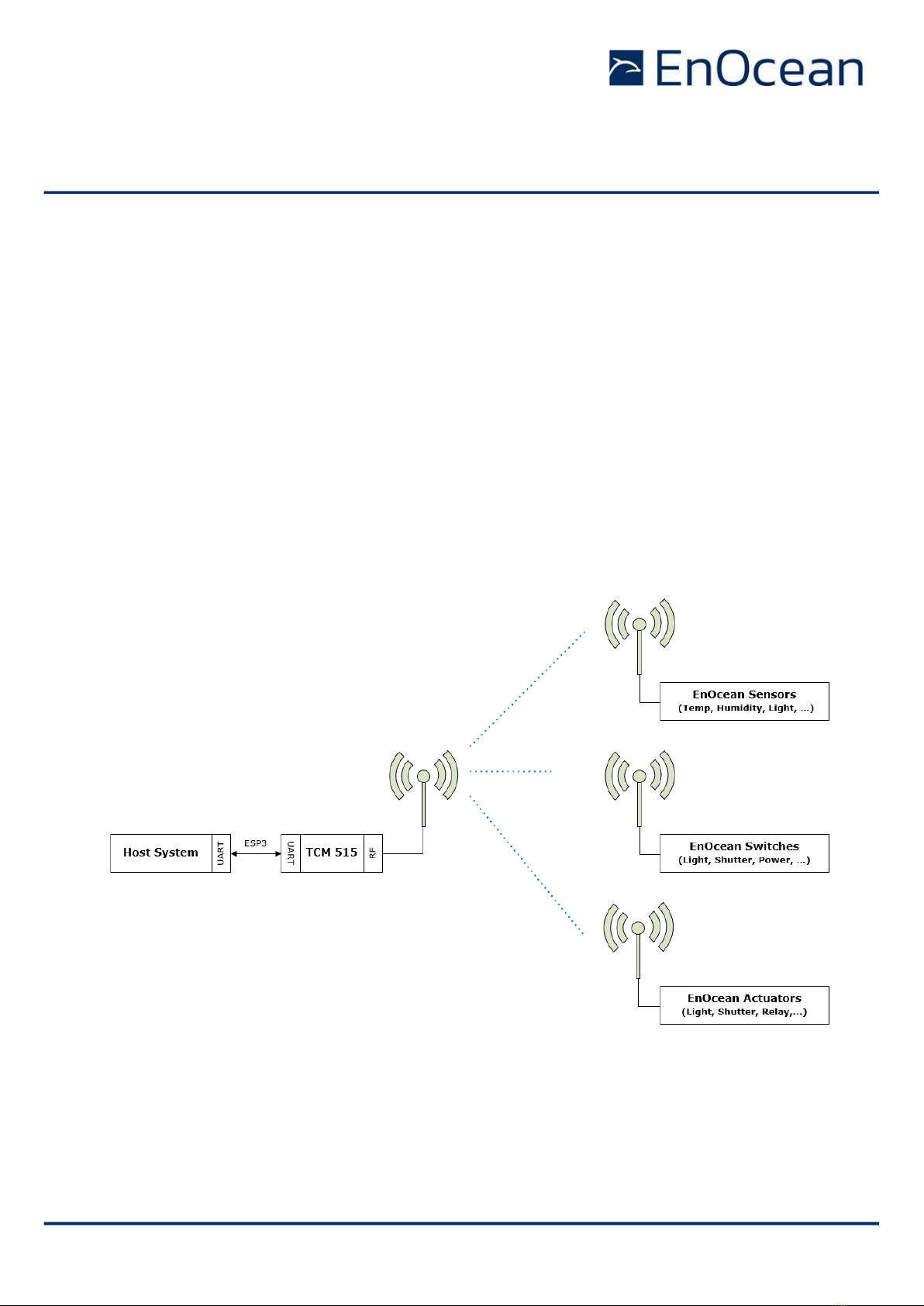
TCM 515 is a fully integrated radio transceiver family which enables communication with
other devices implementing the EnOcean Radio Protocol (ERP) as specified in [2].
TCM 515 is used to exchange (send and / or receive) radio telegrams with external sensors,
switches or actuators.
TCM 515 is connected to an external host which for instance could be a microprocessor, a
controller or a gateway via the EnOcean Serial Protocol v3 (ESP3) interface. ESP3 commands
are listed within this document for information purposes only; for details about ESP3 com-
mands refer to the ESP3 specification [1].
Figure 2 below shows the integration of TCM 515 into a typical system environment.
Figure 2 –TCM 515 system environment
USER MANUAL
TCM 515 / TCM 515U / TCM 515J –ENOCEAN TRANSCEIVER GATEWAY MODULE
© 2023 EnOcean | www.enocean.com F-710-017, V1.0 TCM 515 User Manual | v1.21 | July 2023 | Page 12/120
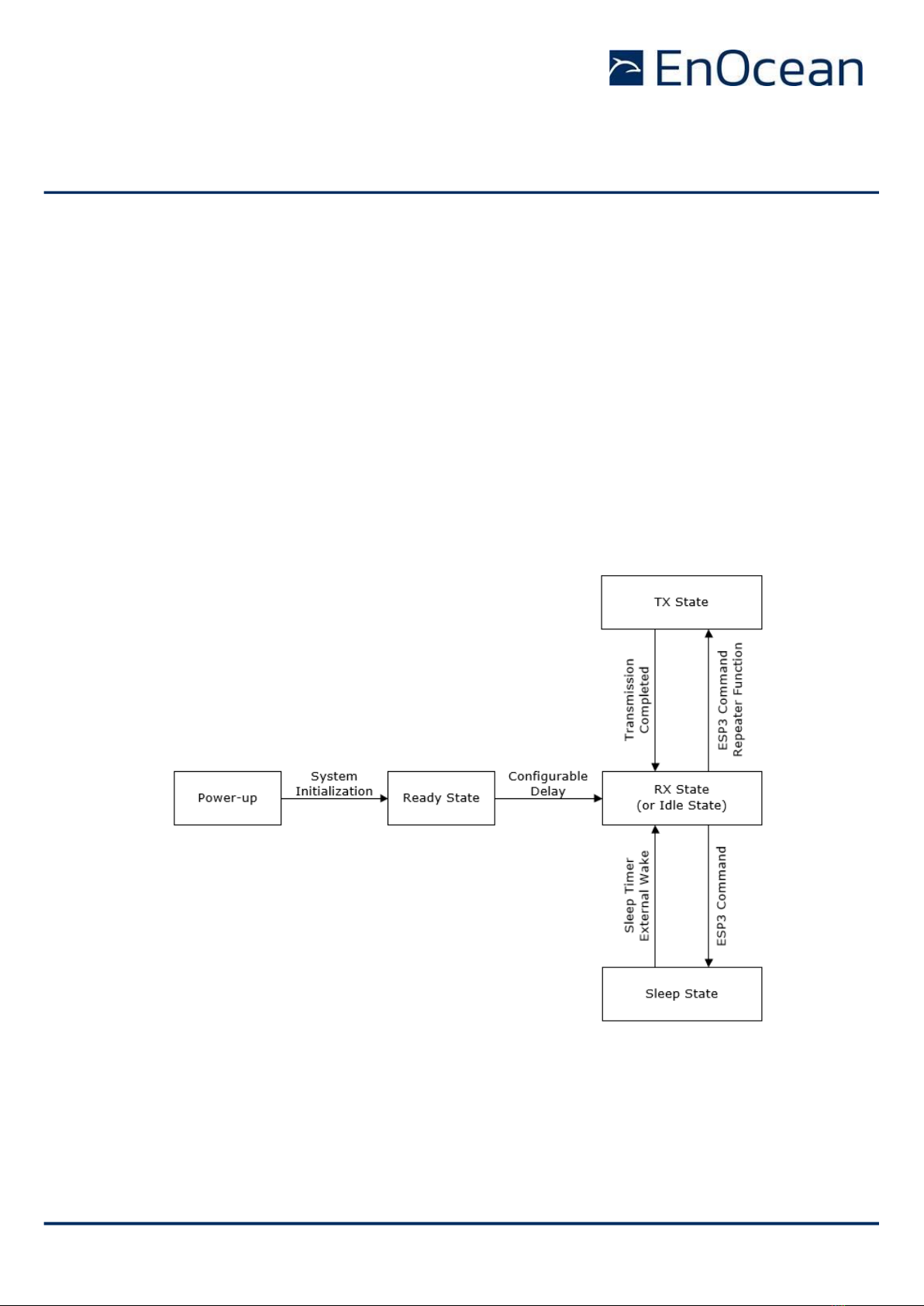
2.2 Functional states
TCM 515 implements the following functional states:
◼Power-up and system initialization (with user-configurable delay)
This state is described in chapter 3
◼RX state (telegram reception with security processing, filtering, repeating as required)
This state is described in chapter 4
◼TX state (telegram transmission with security processing as required)
This state is described in chapter 5
◼Sleep state (low power state to conserve energy)
This state is described in chapter 8
The transition between these functional states is shown in Figure 3 below.
Figure 3 –TCM 515 functional states
Note that it is possible to configure TCM 515 to operate as transmit-only device which disables
receive functionality. If TCM 515 is configured to operate as transmit-only device, then RX
state is replaced by Idle state where TCM 515 will wait for ESP3 commands. Transmit-only
functionality is described in chapter 5.7.

USER MANUAL
TCM 515 / TCM 515U / TCM 515J –ENOCEAN TRANSCEIVER GATEWAY MODULE
© 2023 EnOcean | www.enocean.com F-710-017, V1.0 TCM 515 User Manual | v1.21 | July 2023 | Page 13/120
2.3 Device interface
TCM 515 implements a 31 pin reflow-solderable interface. Solder mask data is available on
request from EnOcean.
2.3.1 Pin-out
The pin assignment (as seen from the top of the TCM 515 device) is shown in Figure 4 below.
Solder mask and mechanical data is available from EnOcean.
Figure 4 –TCM 515 device interface
Table 1 below summarizes the signal assignment.
PIN
NAME
PIN
NAME
PIN
NAME
1
GND
12
NC
23
GND
2
RF_50 (50Ω antenna)
13
NC
24
nRESET (Reset input, active low)
3
GND
14
NC
25
TP1 (Test Interface)
4
NC
15
GND
26
TP2 (Test Interface)
5
NC
16
NC
27
TP3 (Test Interface)
6
GND
17
NC
28
NC
7
NC
18
NC
29
NC
8
NC
19
NC
30
NC
9
NC
20
UART_RX (Input to TCM 515)
31
nTURBO (UART speed, active low)
10
NC
21
UART_TX (Output from TCM 515)
11
NC
22
VDD
Table 1 - TCM 515 pin assignment
Signals marked with “NC” are reserved for production test and future device variants and
must not be connected in the design.

USER MANUAL
TCM 515 / TCM 515U / TCM 515J –ENOCEAN TRANSCEIVER GATEWAY MODULE
© 2023 EnOcean | www.enocean.com F-710-017, V1.0 TCM 515 User Manual | v1.21 | July 2023 | Page 14/120
2.4 Power supply
TCM 515 is supplied by the VDD and GND Pins and supports a supply voltage range between
2.0 V and 3.6 V. For best radio performance it is very important to minimize noise on the
supply voltage lines. Please see chapter 11.5 and 11.6.
The TCM 515 supply voltage must not drop below the minimum permitted supply
voltage of 2.0 V during operation; otherwise correct operation cannot be guaranteed.
Power supply design must account for load transients (e.g. at start-up or wake-up
from Sleep state) and possible voltage drops to provide the required supply voltage.
2.5 Antenna
TCM 515 receives and transmits data based on a 50Ω whip antenna connected to its RF_50
input (Pin 2). Please see chapter 12.
2.6 UART interface
TCM 515 communicates with the external host using the standard ESP3 serial (UART) inter-
face based on the signals UART_TX (Pin 21, direction from TCM 515 to external host) and
UART_RX (Pin 20, direction from external host to TCM 515).
It is strongly recommended that the PCB design provides the ability to connect to the
UART signals –e.g. by means of providing suitable test point pads on the PCB - for
the purpose of analysis and debug.
The default interface speed of the ESP3 interface is 57600 bit per second and data is trans-
mitted using 8 data bits, 1 STOP bit and no parity (8N1).
It is possible to select faster communication speeds during operation using the ESP3
CO_SET_BAUDRATE command (see chapter 9.1). The following interface speeds are sup-
ported by TCM 515:
◼57600 bit per second
◼460800 bit per second
Additionally, it is possible to change the default ESP3 interface speed at power up from
57.600 bit per second to 460.800 bit per second by connecting the nTURBO input (Pin 31,
active low) to Ground.
Subsequent modification of the interface speed during operation using the
CO_SET_BAUDRATE command is always possible irrespective of the state of the TURBO input
pin.
Care should be taken not to select a UART interface speed which cannot be supported
by the connected host processor as this would prevent subsequent communication.

USER MANUAL
TCM 515 / TCM 515U / TCM 515J –ENOCEAN TRANSCEIVER GATEWAY MODULE
© 2023 EnOcean | www.enocean.com F-710-017, V1.0 TCM 515 User Manual | v1.21 | July 2023 | Page 15/120
2.7 Reset
TCM 515 can be reset by pulling the nRESET pin (Pin 24, active low) to Ground. Please see
Chapter 11.8 for reset circuit recommendations.
It is strongly recommended that the PCB design provides the ability to connect to the
nRESET signal –e.g. by means of providing a suitable test point pad on the PCB - for
the purpose of analysis and debug.
2.8 Test interface (TP1, TP2, TP3)
TCM 515 provides a test interface (TP1, TP2 and TP3). The intended use of this interface is
for analysis and debugging of customer products by EnOcean.
It is strongly recommended that customer PCB design provides the ability to connect
external devices to the TP1, TP2 and TP3 signals –e.g. by means of providing suitable
test point pads on the PCB - for the purpose of analysis and debug.
2.9 Product label
Each TCM 515 contains a product label as shown in Figure 5 below.
Figure 5 –TCM 515 product label
The label shown above identifies the following parameters in writing:
◼Product name (TCM 515)
◼Order number (S3003-K515)
◼Product revision (DD-19)
◼Manufacturing date (week 25, 2021)
◼Manufacturer traceability code (592001002206)

USER MANUAL
TCM 515 / TCM 515U / TCM 515J –ENOCEAN TRANSCEIVER GATEWAY MODULE
© 2023 EnOcean | www.enocean.com F-710-017, V1.0 TCM 515 User Manual | v1.21 | July 2023 | Page 16/120
2.9.1 QR code
The TCM 515 product label contains an automatically readable QR code in the lower right
corner which encodes certain product parameters according to the ANSI/MH10.8.2-2013
standard as listed in Table 2 below.
Data Identifier
Data Length
(excluding identifier)
Data Content
30S
8 characters (hexadecimal)
EnOcean Universal Radio ID (EURID)
30P
10 characters (alphanumeric)
Ordering Code
2P
4 characters (alphanumeric)
Step Code and Revision
S
14 characters (decimal)
Serial Number (starts with 01)
Table 2 –TCM 515 product QR code structure
USER MANUAL
TCM 515 / TCM 515U / TCM 515J –ENOCEAN TRANSCEIVER GATEWAY MODULE
© 2023 EnOcean | www.enocean.com F-710-017, V1.0 TCM 515 User Manual | v1.21 | July 2023 | Page 17/120
3Power-up, initialization and system operation
After power-up, TCM 515 executes the following steps:
◼Initialization of the system
TCM 515 initializes all system components and peripherals.
After that, TCM 515 transitions to Ready state
◼Wait for pre-configured delay
This delay allows the power supply to stabilize and the external host to initialize the
system. The default value of this delay is 200 ms; this is configurable This delay can
be configured as persistent parameter (maintained after power down) using the ESP3
command CO_WR_STARTUP_DELAY.
After that, TCM 515 is in ready for operation depending on the selected TCM 515 operation
mode (transmit and receive mode or transmit-only mode).
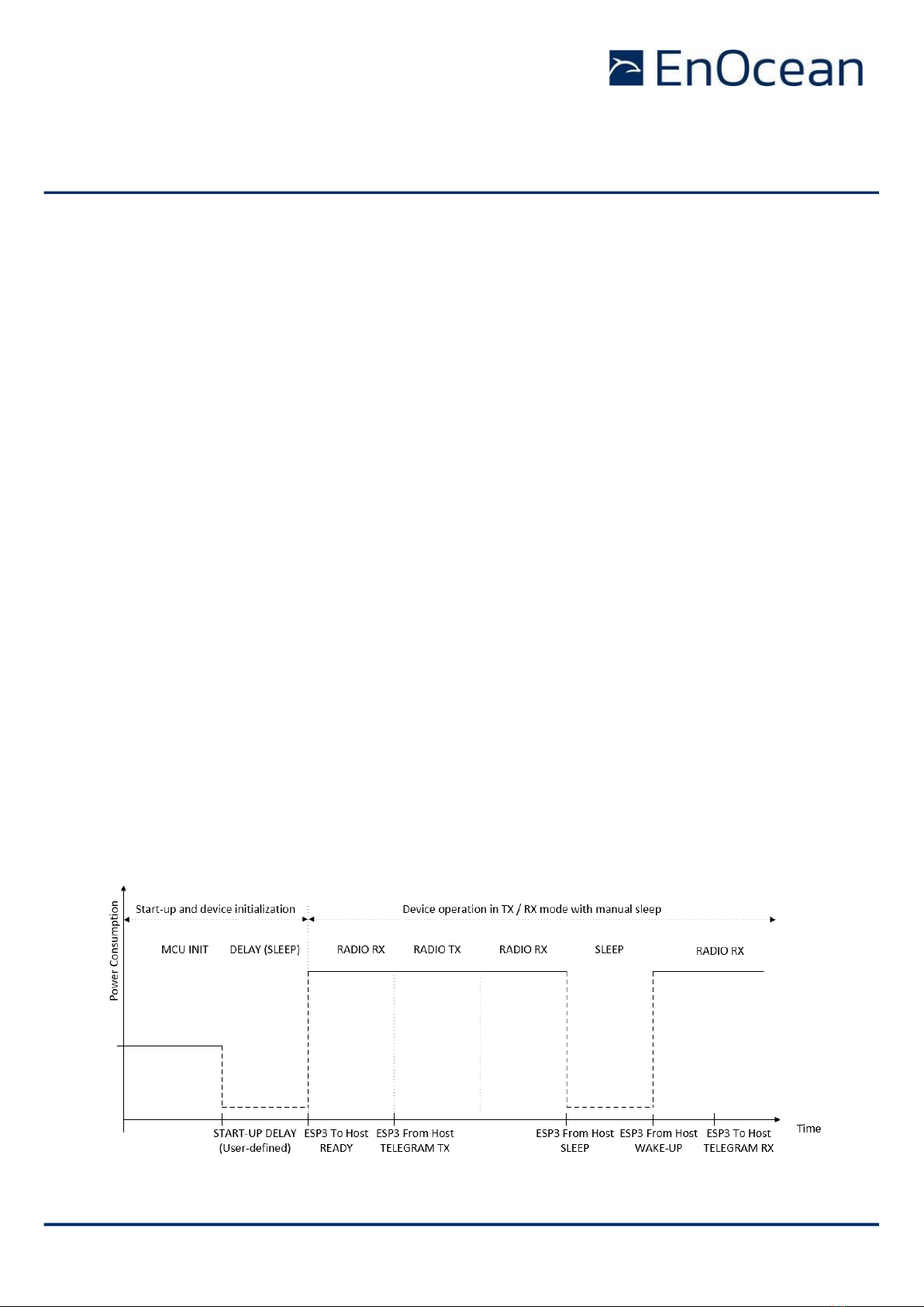
3.1 Typical operation sequence for transmit and receive mode
The default configuration of TCM 515 is transmit and receive mode. In this mode, TCM 515
is continuously scan for EnOcean radio telegrams in RX state unless it receives a request
from the host to transmit a telegram.
If TCM 515 receives a valid EnOcean radio telegram, then it will process this as described in
chapter 4 and forward it to the host via ESP3.
If TCM 515 receives a request from the host to transmit a telegram, then it will transition to
TX state and transmit the telegram as described in chapter 5. After that, it will automatically
transition back to RX state and continue to scan for EnOcean radio telegrams.
Figure 6 below shows a typical operation sequence for transmit and receive mode with man-
ual sleep entry and exit.
Figure 6 –Operation sequence for transmit and receive mode with manual sleep

USER MANUAL
TCM 515 / TCM 515U / TCM 515J –ENOCEAN TRANSCEIVER GATEWAY MODULE
© 2023 EnOcean | www.enocean.com F-710-017, V1.0 TCM 515 User Manual | v1.21 | July 2023 | Page 18/120
3.2 Typical operation sequence for transmit-only mode
In transmit-only mode, TCM 515 will wait in Idle state until an ESP3 command from the host
requesting the transmission of a telegram has been received. It will then transmit the tele-
gram as described in chapter 5 and inform the host once the transmission of a telegram has
been completed.
After completion of the telegram transmission, TCM 515 will either transition back to Idle
state waiting for the next command from the host (default configuration) or automatically
enter Sleep state waiting for a wake-up via ESP3 command (Auto Sleep configuration).
Figure 7 below shows a typical operation sequence for transmit-only mode with automatic
sleep entry (Auto Sleep). See chapter 5.7 for a detailed description of transmit-only mode.
Figure 7 –Operation sequence for transmit-only mode with Auto Sleep

USER MANUAL
TCM 515 / TCM 515U / TCM 515J –ENOCEAN TRANSCEIVER GATEWAY MODULE
© 2023 EnOcean | www.enocean.com F-710-017, V1.0 TCM 515 User Manual | v1.21 | July 2023 | Page 19/120
4Telegram reception
After start-up, TCM 515 will enter receive state unless TX-only mode is active as discussed
in chapter 5.7.
4.1 Telegram reception flow
While in receive state, TCM 515 will wait for valid EnOcean radio telegrams and then performs
the following functions:
◼RX telegram processing
Received data bitstream is processed (detection and removal of preamble, start of
frame, end of frame and redundant bits, CRC check, subtelegram merge) and format-
ted as EnOcean radio telegrams
◼Repeater handling
Received telegrams are checked if they should be repeated based on the repeater
mode configured at TCM 515 (Level1 Repeater, Level2 Repeater, Selective Repeater)
and the repeater information reported as part of the radio telegram. If the received
telegram should be repeated, then it will be inserted into the transmission queue. See
chapter 5.7 for details on the repeater functionality.
◼Telegram filtering
Received telegrams can be classified according to user-defined characteristics so that
only telegrams matching these characteristics will be processed and forwarded to the
external host via the ESP3 interface. See chapter 4.2 for details.
◼Security processing
Telegrams from senders using high security mode can be automatically decrypted and
authenticated according to their security parameters stored in the inbound secure link
table. See chapter 7 for details.
◼ESP3 formatting and telegram forwarding
Processed telegrams will be formatted as ESP3 packet (RADIO_ERP1 by default) and
forwarded to the external host via the ESP3 interface. See chapter 9 for details re-
garding the ESP3 interface.
Figure 8 below shows the processing flow for received telegrams.
Figure 8 –Telegram Reception Flow

USER MANUAL
TCM 515 / TCM 515U / TCM 515J –ENOCEAN TRANSCEIVER GATEWAY MODULE
© 2023 EnOcean | www.enocean.com F-710-017, V1.0 TCM 515 User Manual | v1.21 | July 2023 | Page 20/120
4.2 Telegram filtering
By default, TCM 515 will forward all valid telegrams received by it (including such that are
addressed to a different receiver) to the host via its ESP3 interface.
Additionally, TCM 515 will repeat all received telegrams if repeating is enabled.
Filtering allows the host to configure via the ESP3 interface conditions based on which tele-
grams are forwarded to the host or repeated. Telegram filtering is based on the following
parameters:
◼Filter type
The filter type defines based on what property TCM 515 should evaluate in received
telegrams, e.g. if it should check the source address, the destination address, the
telegram type or the signal strength
◼Filter value
The filter value defines the reference value against which TCM 515 will compare the
property of the received telegram
◼Filter condition
The filter condition defines the desired relation between the defined filter value and
the corresponding property of the received telegram.
For the case of source address, destination address and R-ORG, the filter condition
can be Equal (e.g. the source address of received telegram is the same as the defined
filter value) or Not Equal (e.g. the R-ORG of the received telegram is not the same as
the defined filter value).
For the case of signal strength, the filter condition can be Lower Than Or Equal (the
received signal strength is lower than the defined value or equal to it) or Higher Than
(the received signal strength is higher than the defined value).
◼Filter action
The filter action defines what TCM 515 should do if the filter condition is true, e.g. if
it should forward the telegram to the host or if it should forward the telegram to the
host and repeat the telegram
◼Filter combination
The filter combination defines what happens if more than one filter condition is defined
for a specific set filter action, e.g. if the filters controlling telegram forwarding to the
host should be combined in a logic OR fashion or a logic AND fashion.
The following chapters describe these parameters in more detail.
This manual suits for next models
2
Table of contents
Other EnOcean Gateway manuals


Popular Gateway manuals by other brands

Power Inspired
Power Inspired GABY quick start guide

ICPDAS
ICPDAS ECAT-2610 user manual

Alphatech
Alphatech BlueGate SIP Quick installation guide

Planet Networking & Communication
Planet Networking & Communication IMG-120T user manual

Leviton
Leviton DRCDD-L0 installation instructions

ADTRAN
ADTRAN SMART/RG SR516ac quick start guide


