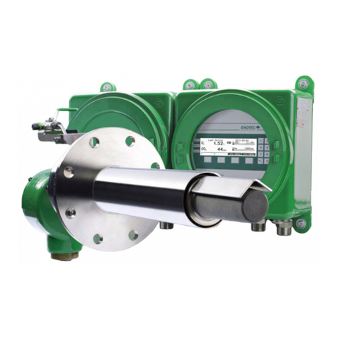
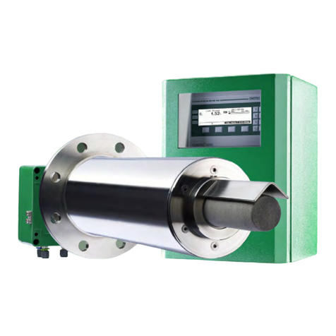
Enotec ENSITU 7000 User manual

Doc.-ID: ENS_13062019-EN
Installation and Operation Manual
O
2
Transmitter Probe
ENSITU
®
7000
Version 04

Doc.-ID: ENS_13062019-EN
Preface
Dear Customer,
Thank you for selecting ENSITU®7000 as your InSitu flue gas oxygen analyzer.
Since 1980 our analyzer systems have been operating in numerous applications with tens of thousands
of units being produced and shipped worldwide. ENOTEC is committed to absolute quality and
performance and over time we have continuously enhanced our products to integrate various features
and functions.
ENOTEC probes include the zirconium oxide sensor which has a gas-tight seal made by using a special
process and technique developed by ENOTEC. This leads to a considerably increased service life
compared to "glued or cemented" sensors that have a tendency to leak or crack during operation.
All ENOTEC instruments are thoroughly tested in the factory and are subject to a strict ISO9001 Quality
Assurance Procedure. Therefore, with the correct installation, the operation of the ENSITU®7000 is very
straightforward and user friendly and will provide many years of trouble free operation with perfect
measuring results.
Symbols used in this Manual
Warning
Follow all instructions in the manual
Consider Information
Points out important information which
must be considered before execution
Warning hot surface
Warns of danger of burns which could
occur from hot system parts
Note
Contains further detailed information
Attention
Warns of risks by destroying the system
or its components or its functionality
Ground earth electrical protection
The contents of this manual are protected by copyright. Alterations and errors reserved.
Safety Instruction
After removal of terminal covers some parts of this system may be accessible which are under voltage.
Only well trained and authorized personnel are allowed to work on this system. The personnel must
know and understand all precautions, safety, installation and maintenance instructions of this manual.
The trouble free and safe operation of the ENSITU®7000 requires safe transportation, professional
storage, installation, operation and maintenance.
Furthermore all local safety and legal requirements at the point of installation and operation must be
considered.
The ENSITU®7000 may not be used to measure oxygen in combustible gases or in an environment
with combustible gases as the heated sensor may cause an explosion risk.

Installation and Operation Manual - ENSITU®7000 Table of Contents
Doc.-ID: ENS_13062019-EN 1
Table of Contents
1System Description 2
1.1System Overview ................................. 2
1.2Measuring Principle.............................. 4
1.3Intended use......................................... 4
1.4Safety Hazards..................................... 4
1.5Disruption of the Process ..................... 5
1.6Storage instructions.............................. 5
1.7Name Plates......................................... 5
2Installation 6
2.1Installation of the probe ........................ 6
2.2Adjusting the V-shield........................... 7
2.3Mounting of the Probe .......................... 7
2.4Connection of the probe plug for
detached electronics ............................ 8
2.5Access to the Terminals ....................... 8
2.6Wiring Diagram of the Electronic Unit .. 9
2.7Test gas connection / reference air ports
........................................................... 10
3Software and Analyzer Control 11
3.1Installation of the ENOTEC Remote App
........................................................... 11
3.2Establish a connection ....................... 12
3.2.1Search for available analyzers ........... 12
3.2.2Pair with the Analyzer......................... 12
3.2.3Connect with the ENSITU 7000®
Analyzer ............................................. 13
3.2.4Enter the Pin Code ............................. 14
3.3Screen Overview ................................ 14
3.4Change access level .......................... 15
3.5Save and Share System Protocols..... 15
3.6O2Sensor Calibration......................... 16
4Initial Operation 17
4.1Checklist before start-up of the Analyzer
........................................................... 17
4.2System power up................................ 17
4.3Display and LEDs............................... 17
5Service and Maintenance 18
5.1Preparation of the test gas tubing ...... 18
5.2Connect the test gas tube .................. 18
5.3Test air / test gas supply to the probe for
calibration ........................................... 18
5.3.1Test air supply with pump................... 18
5.3.2Test air supply with instrument air...... 19
5.3.3Test gas / Test air supply (certified test
gas) .................................................... 19
5.4Exchange fuses...................................19
5.5Exchange of the probe inner part........20
5.6Replacing the Filter .............................21
5.6.1Remove the old Filter ..........................21
5.6.2Cement in the new Filter .....................21
6Error Codes 22
7Troubleshooting 24
ATechnical Specifications 25
A.1Technical specifications - KES-700X .25
A.2Technical Specifications - Electronics
unit ......................................................26
A.3Technical Specifications - General.....26
A.4Technical Specifications......................27
BDimensional Drawings 28
B.1Dimensional drawings of the KES-700X
probes .................................................28
B.2Counter flange ADP-7000 ...................29
B.3KES-700X Probe inner parts...............30
CSpare Parts 31
C.1Probe components ..............................31
DWarranty 32
Index 33

System Description
Installation and Operation Manual - ENSITU®7000
2 Doc.-ID: ENS_13062019-EN
1 System Description
1.1 System Overview
Figure 1 – ENSITU®7000 transmitter probe
Electronic unit Safe Area
Max. ambient temp.: -40 °C to +70 °C (-40 °F to +158 °F)
InSitu measuring probe Duct / combustion chamber
Probe flange Flue gas direction
Max. process gas temp: 600 °C (1112 °F)
Counter flange (Optional)
Isolation Customer supply
Manufacturer supply
Duct wall Customer supply
Power supply 48V DC , 5A max.-
Optional: Power adapter from ENOTEC
Max. cable length, 50 m
Input and output signals (analog and digital)
Test air / test gas in

Installation and Operation Manual - ENSITU®7000
System Description
Doc.-ID: ENS_13062019-EN 3
Figure 2 – ENSITU®7000 transmitter probe - electronics detached
Electronic unit - detached Safe Area
Max. ambient temp.: -40 °C to +70 °C (-40 °F to +158 °F)
InSitu measuring probe Safe Area
Max. ambient temp.: -40 °C to +80 °C (-40 °F to +176 °F)
Probe flange Duct / combustion chamber
Counter flange (Optional)
Isolation Customer supply
Flue gas direction
Max. process gas temp: 600 °C (1112 °F)
Duct wall Manufacturer supply
Cable with plug. Max. cable
length + = 50 m
Customer supply
Power supply 48V DC, 5A max.
Optional: Power adapter from ENOTEC
Max. cable length + = 50 m
Input and output signals (analog and digital)
Test air / test gas in

System Description
Installation and Operation Manual - ENSITU®7000
4 Doc.-ID: ENS_13062019-EN
1.2 Measuring Principle
The ENSITU®7000 O2probe is installed in a duct to measure O2in non-combustible process
gases and is coupled with an electronic unit for voltage and signal processing.
The oxygen sensor is at the tip of the probe and is regulated to 800 °C and works on the
zirconium oxide principle of measurement. Here, a mV signal between the reference gas side of
the sensor (inside, 20.95 % O2dry) and the measured gas side is measured, which depends
logarithmically on the ratio of oxygen partial pressures on both sides of the sensor.
The mV signal is converted according to the Nernst equation into oxygen partial pressure within
the process gas, whereby the O2concentration is determined in the process gas. Gas-tight
separation of reference air and process gas is of particular importance.
Should combustible components such as CO or H2be present in the sample gas, they will react
with oxygen at the sensor surface and can reduce the measured value.
1.3 Intended use
Info
The ENSITU®7000 analyzer system is a system for measuring the oxygen concentration in flue
gases and other non-combustible gases. For reasons of safety and the possibility of accidents,
unauthorized conversions and modifications of the system are prohibited.
Warning
The system cannot be used to determine the oxygen concentration of combustible gases or in a
location where combustible gases are present as the sensor temperature of 800 °C could
present an explosion hazard!
Info
The minimum concentration of O2 in flue gas should under normal process conditions, not be
less than 0.5 %.
Caution
Under no circumstance should the measuring probe be directly connected to the 230 V / 115 V
main power supply as this will immediately destroy the probe heater element!
1.4 Safety Hazards
Warning hot surface
During operation, the temperature of the probe filter head and of other parts exposed to flue gas
is up to 800 °C (1472 °F). Direct contact with the hot parts when dismantling or maintenance will
cause severe burns!
The probe may only be removed with heat-insulated gloves. Before removing the probe, always
switch off the supply voltage. After removal, store the probe in a safe, protected place and wait
until it has cooled down below 35° C (95° F).

Installation and Operation Manual - ENSITU®7000
System Description
Doc.-ID: ENS_13062019-EN 5
1.5 Disruption of the Process
The analyzer system has to be kept in operation also in the event of the process being
disrupted or if the plant is powered off temporarily (e.g. at night or during the weekend).
Frequently cooling down and heating up of the probe results in thermal stress of the hot probe
parts (heater, thermocouple and sensor) and reduces their product life. ENOTEC will not accept
any responsibility for resultant damage.
1.6 Storage instructions
ENOTEC equipment and spares are to be stored in a dry and ventilated environment. Paint
fumes, silicone sprays, etc. must be avoided in the storage environment.
1.7 Name Plates
The name plate contains information about the voltage, the nominated current, frequency,
protection class and serial number. The serial number refers to information which is detailed in
the system test report and supplied with the system.
Electronics name plate Probe name plate
Figure 3 – Position of the name plates

Installation
Installation and Operation Manual - ENSITU®7000
6 Doc.-ID: ENS_13062019-EN
2 Installation
Warning
The system is not equipped with an external power-off switch. The line voltage
switch/fuse/breaker must be installed and be in accordance with local technical standards and
should be near to the electronic unit and must be clearly marked as such. Before removal of the
electronic terminal cover the line voltage must be switched off. The line voltage to the electronic
unit must be switched on again after the cover is back in position. After installation power
conducting parts may not be accessible.
2.1 Installation of the probe
The flue gas temperature, pressure and all other process conditions must be in accordance with
the specification. Leave enough space for insertion/removal of the probe.
Before cutting a hole in the flue gas duct, make sure that the inside of the duct has enough
space for probe installation and that no fly ash is blown out nearby or any obstacles are in the
way.
ENOTEC recommends installing the probe horizontally (-3 ° to - 5 °) for fastest possible
response times.
Transmitter probe
Maintain ambient and process temperature
limits.
Probe with detached electronics
Maintain ambient and process temperature limits
Maintain the protection class
Avoid vibrations > 2g

Installation and Operation Manual - ENSITU®7000
Installation
Doc.-ID: ENS_13062019-EN 7
2.2 Adjusting the V-shield
The filter head is 360° rotatable and must be adjusted so that the filter abrasion shield faces the
oncoming flue gas.
Before installing the probe, the direction of flue gas flow must be determined and the filter
head assembly turned to such a position that the V-shield faces the oncoming flue gas. Loosen
the counter nut , loosen the screw and rotating the filter head / abrasion shield to the
required position, tighten the screw and counter nut.
Flue gas direction
Abrasion shield
Filter
Filter head
Screw
Counter nut
Flange
Test gas connection
Electronic unit
Figure 4 - Adjustment of the
abrasion shield
2.3 Mounting of the Probe
Insulation (customer supply)
Counter flange
(optional ENOTEC supply)
Flange gasket
Bolts
Electronic unit
Figure 5 - Mounting of the Probe – for dimensions, see chapter B.

Installation
Installation and Operation Manual - ENSITU®7000
8 Doc.-ID: ENS_13062019-EN
2.4 Connection of the probe plug for detached electronics
Contact Polarity Description
1, 2 + Probe heater
3
+ Probe data board
4
+ Thermocouple
5
+ O2sensor
6, 7
-
Probe heater
8
-
Probe data board
9
-
Thermocouple
10
-
O
2sensor
Figure 6 - Probe plug connection for detached electronics.
See Figure 2 for configuration and chapter 0 for cable specifications.
2.5 Access to the Terminals
Warning
Power supply lines are to be connected / disconnected only in a de-energized state as not to
risk a short circuit.
Remove the 2 clips at the sides of
the terminal box,
loosen the 4 captive screws ,
open the constrained terminal box lid
from the top .
Figure 7 - Access to the Terminals
Warning
Tighten the screws for the terminal box lid with a torque of 3 Nm.

Installation and Operation Manual - ENSITU®7000
Installation
Doc.-ID: ENS_13062019-EN 9
2.6 Wiring Diagram of the Electronic Unit
Figure 8 - Wiring diagram of the
ENSITU®7000
Electronic Unit
+
48 V DC 5A Power supply
-
1 + 4-20 mA Sink
O2analog output2
-
+ 4-20 mA Source
3 -
4 +
24V DC = Active O2zero point calibration
5 -
6 Shield
7 Reserved
8 Reserved
9 Reserved
10 Shield

Installation
Installation and Operation Manual - ENSITU®7000
10 Doc.-ID: ENS_13062019-EN
2.7 Test gas connection / reference air ports
Figure 9 - Overview of test gas connection / reference air ports
Test gas
connection
The test gas connection is equipped with a check valve with
1/4" parker connection for 1 or 2-point calibration purposes.
See chapter 3.6 for the calibration procedure.
If instrument air is available, it should be used for 1-point calibration
purposes:
Test air / test gas flow rate, 150 – 180 l/h
Reference air in /
Reference air out
The reference air ports allow for sufficient supply of ambient air as
reference air to the reference side of the sensor. The ports are
equipped with screw-in aeration membranes to prevent the ingress of
water or dust.
Alternatively, should the ambient air be contaminated with exhaust
fumes or have a high humidity which could influence the O2
measurement, one of the ports can be used for the connection of
instrument air (according to ISO 8573-1 class 2) as reference air (in
this case instrument air should also be used as test air).
The second unused port acts as reference air outlet.
The following must be noted in this case:
The screw-in aeration membrane must be removed from the
port where the instrument air is connected.
Instrument air flow rate, 15 - 20 l/h

Installation and Operation Manual - ENSITU®7000
Software and Analyzer Control
Doc.-ID: ENS_13062019-EN 11
3 Software and Analyzer Control
Info
ENSITU®7000 has no interface to interact with and can be controlled via smartphone or tablet
running the Android operating system over a Bluetooth connection using the ENOTEC Remote
app.
The interface language of the app will be the system language on the Android smart device.
Available languages are English, German and Spanish.
3.1 Installation of the ENOTEC Remote App
Download and install the ENOTEC Remote app, which is
available free of charge on the Google Play Store.
The app requires an Android smart device (Smartphone / Tablet)
with software version 4.1.2 or higher and Bluetooth.

Software and Analyzer Control
Installation and Operation Manual - ENSITU®7000
12 Doc.-ID: ENS_13062019-EN
3.2 Establish a connection
3.2.1 Search for available analyzers
In connection distance to the ENSITU analyzer, start the
ENOTEC Remote app and search for available
analyzers.
Figure 10 – Search for available analyzers
3.2.2 Pair with the Analyzer
The ENSITU®7000 analyzer will appear in the list of
Bluetooth enabled devices on your smart device. Tap on
the analyzer name.
The blue LED of the analyzer will now blink.
Tap the back arrow to return to the ENOTEC Remote
app.
Should the ENSITU®7000 analyzer not appear in the list,
check the following:
Is the analyzer switched on?
Are analyzer and smart device in connection distance
to eachother?
Figure 11 – Pair with the ENSITU 7000®

Installation and Operation Manual - ENSITU®7000
Software and Analyzer Control
Doc.-ID: ENS_13062019-EN 13
3.2.3 Connect with the ENSITU 7000®Analyzer
List of paired analyzers - tap to control this
analyzer.
FAQ and troubleshooting.
Cloud and other settings.
Cloud storage is not hosted by ENOTEC GmbH.
Users of the ENOTEC Remote app can find help
for the standalone setup of the cloud at
http://www.owncloud.org.
QR code reader to transfer sensor parameters to
the analyzer.
Search for Bluetooth enabled ENOTEC analyzers.
Lists the system protocols stored on the smart
device.
Figure 12 - Connect with the ENSITU®7000
The ENSITU®7000 analyzer is now paired with the smart device and will remain in the paired
analyzers list. Tap the analyzer which is to be controlled.
The analyzer name is freely changeable in the settings menu. It is recommended to give the
analyzer an individual name (e.g TAG Nr.).

Software and Analyzer Control
Installation and Operation Manual - ENSITU®7000
14 Doc.-ID: ENS_13062019-EN
3.2.4 Enter the Pin Code
Enter the pin code. Default at delivery is 0000 0000.
Once a connection has been established between the
smart device and ENSITU®7000 the blue REMOTE LED
will remain lit.
Should the pin be unknown, the mainboard serial number
can also be used as pin. Open the terminal box lid as
described in chapter 2.5 to reveal the mainboard serial
number.
For security reasons, the authentication pin must be
changed to a more secure pin in the analyzer settings.
Figure 13 – Enter the authentication pin code
3.3 Screen Overview
Figure 14 - Screen Overview
Displays the currently measured O2value.
Detailed measured values.
Current screen – overview of measured values.
Displays previous calibration results (last 20).
Swipe left or right to display individual calibrations.
Displays detailed analyzer information.
ENSITU®7000 settings.
Check the mA output using a current measuring
instrument such as a multimeter (System access).
Calibrate the O2sensor – see chapter 3.6.
Save all analyzer information on the smart device
or in a private cloud, send the file electronically.
Service menu (hidden in normal state, contact
ENOTEC).
Disconnect from the analyzer.
Appears when a warning occurs. Tap for details.
Appears when an error occurs. Tap for details.
Change access levels. See chapter 3.4.
Displays the connection quality to the analyzer.
The lower the value the better.

Installation and Operation Manual - ENSITU®7000
Software and Analyzer Control
Doc.-ID: ENS_13062019-EN 15
3.4 Change access level
To protect the analyzer from unauthorized usage,
certain functions are secured by access levels.
Tap the lock to choose the required access level
"Public" access level is set by default; no changes to
analyzer parameters are possible.
The default PIN code for “System” access level is 0000
which will allow access to all standard analyzer
functions such as configuration of the measuring range
or calibration.
Figure 15 – Change access level
3.5 Save and Share System Protocols
Info
The ENOTEC Remote app can save all relevant analyzer and process information to an HTML
file. This file can be saved locally or be sent to an ENOTEC service point for analysis.
Enter the „Archive“ menu.
Tap “CREATE SYSTEM PROTOCOL” and
choose to save the protocol locally or save and
send it electronically (internet connection
necessary).
Cloud storage is also possible, see chapter 3.2.3.
Storage location on smart device.
List of saved system protocols, tap to open.
Figure 16 – System protocols

Software and Analyzer Control
Installation and Operation Manual - ENSITU®7000
16 Doc.-ID: ENS_13062019-EN
3.6 O
2
Sensor Calibration
Info
To achieve a higher accuracy, a calibration can be carried out. An O2sensor calibration can be
started as soon as high gas (e.g. instrument air or ambient air, 20.95 vol. % O2) or low gas
(certified bottled test gas, e.g. 2.1 vol. % O2) is applied to the test gas port at a flow rate of 150 –
180 l/h. See chapter 5.3 for additional information.
The difference between high and low test gas O2concentration must be at least 5.00 %.
The minimum O2concentration of the low test gas is 0.20 %.
A 1-point calibration always takes place if the analyzer cannot determine a previous valid
calibration value as reference value. A 1-point calibration can be carried out with high or low test
air or test gas. The sensor offset is adjusted by a 1-point calibration and will adjust the
parameter "O2sensor offset".
A 2-point calibration is carried out when the complementary gas of the previous calibration is
applied and must take place within two hours to the previous calibration.
The 2-point calibration will adjust the parameters "O2sensor offset" and "O2sensor slope”.
Figure 17 – O2sensor calibration
Once test air / test gas has been applied to the probe test gas port, initiate the calibration by
tapping the Cal. button . Sensor signal stability must be reached before the calibration
can take place. The stability progression is depicted with the orange circle . Once the sensor
signal is stable, “ACCEPT MEASURED VALUE” will appear and must be confirmed.
The calibration progression bar becomes green as soon as sensor stability is reached.
Follow the onscreen instructions carefully to complete the calibration.

Installation and Operation Manual - ENSITU®7000
Initial Operation
Doc.-ID: ENS_13062019-EN 17
4 Initial Operation
4.1 Checklist before start-up of the Analyzer
Make sure that there are no leakages at the probe - e.g. is the counter flange welded gas tight
to the duct and are the flange bolts tightened sufficiently? Are new gaskets in use? Are the
cable glands tightened sufficiently
See section 2.3 - Mounting of the Probe.
Do the conditions at site match the specification in the data sheets?
See section A - Technical Data.
4.2 System power up
Switch on the power supply to the analyzer. The sensor heating phase will start immediately
which is followed by measuring mode.
4.3 Display and LEDs
Figure 18 – ENSITU®7000 display with LEDs
Display
Measured O2value
(or) sensor heating phase
(or) error code
Green
LED
Blinks during heating phase.
Lit when measurement is valid
Blue
LED
Lit when an ENOTEC Remote
connection is active
Red
LED
Lit when an error has occurred
and the error has not been
rectified
Blinks when an error has
occurred, has been rectified
but not acknowledged
Measuring mode showing the currently measured O2 value
Upper row/O2value (blinking alternately) – O2over range
Lower row/O2value (blinking alternately) – O2under range
Sensor heating phase (°C)
Error code – See chapter 6
Figure 19 – ENSITU®7000 display

Service and Maintenance
Installation and Operation Manual - ENSITU®7000
18 Doc.-ID: ENS_13062019-EN
5 Service and Maintenance
Warning Hot Surface
The probe may only be removed with heat-insulated gloves. Before removing the probe, always
switch off the supply voltage to the electronics. After removal, store the probe in a safe,
protected place and wait until it has cooled down below 35 °C/ 95 °F.
Info
After exchanging parts or servicing the ENSITU®7000 whereby the system was switched off, it
is recommended to carry out a 1-point calibration 24 hours after the system has been switched
back on.
5.1 Preparation of the test gas tubing
Test gas tube (customer) ¼'' or 6/4mm OD/ID
Nut (Manufacturer supply)
Seal (Manufacturer supply)
Support sleeve (Manufacturer supply)
Figure 20 – Preparation of the test gas port
5.2 Connect the test gas tube
Remove the sealing cap
Screw on the test gas tube
Figure 21 – Connect the test gas tube
5.3 Test air / test gas supply to the probe for calibration
5.3.1 Test air supply with pump
Pump
Flow meter (150 … 180 l/h)
Figure 22 - Test air supply with a
pump using ambient air
Table of contents
Other Enotec Measuring Instrument manuals
Popular Measuring Instrument manuals by other brands
Hanna Instruments
Hanna Instruments Chromium VI quick start guide
Leuze
Leuze AMS 307i Original operating instructions
Racal Instruments
Racal Instruments 9916 Workshop manual

Konica Minolta
Konica Minolta CHROMA METER CS-200 instruction manual
Keysight Technologies
Keysight Technologies FieldFox B Series user guide
Panasonic
Panasonic k-nl304k user manual
