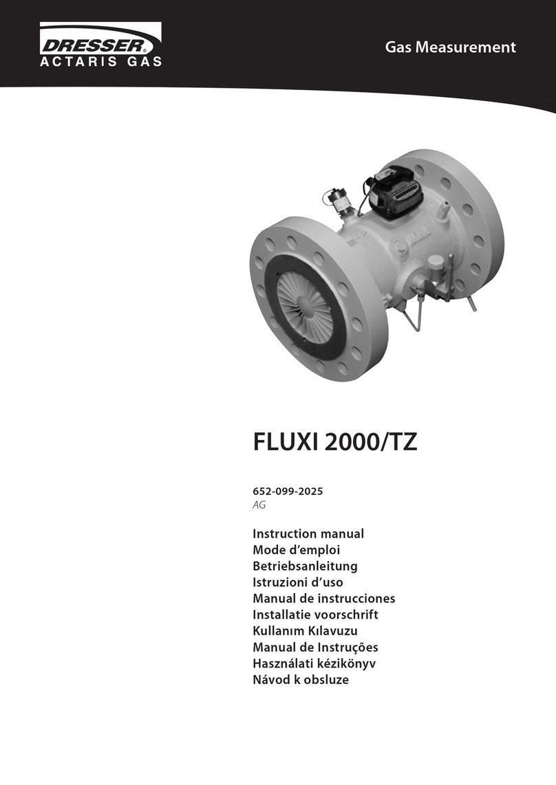
Dresser FLUXI 2000/TZ User manual

FLUXI 2000/TZ
652-099-2025
AD: 2019/07/02
Instruction manual
Mode d’emploi
Betriebsanleitung
Istruzioni d’uso
Manual de instrucciones
Installatie voorschrift
Kullanım Kılavuzu
Manual de Instruções
Használati kézikönyv
Gas Measurement

D2035936_AJ_EU_Declaration_TZ.doc
EU Declaration of Conformity
Itron GmbH
Hardeckstrasse 2
D-76185 Karlsruhe
Declares under his sole responsibility that the product turbine meter Fluxi 2000/TZ is designed
and manufactured in conformity with the following Directives:
1. Directive 2014/68/EU (PED) Modules B+D Category IV
- DIN EN 12261:2007-07
Certificate: DVGW CE-0085BM 0417
The module D is supervised by:
#0036 TÜV SÜD Industrie Service GmbH, Westendstr. 199, D-80686 München
The used fluids are classified in group 1 according article 13.
Certificate: DGR-0036-QS-955-17
2. Directive 2014/30/EU (EMC)
- EN 60947-5-2:2007/A1:2012
- EN 61000-6-2:2005/AC:2005
- EN 61000-6-3:2007/A1:2011/AC:2012;
3. Directive 2014/34/EU (ATEX)
- EN 60079-0:2012/A11:2013
- EN 60079-11:2012
- EN 13463-1:2009
- EN 13463-5:2011
Certificate: LCIE 06 ATEX 6031 X
II 1/2 G Ex ia IIC T5 Ga / Gb c T6
#0081 LCIE 33 avenue General Leclerc, F-92266 Fontenay-aux-Roses
The module D is supervised by:
#0123 TÜV SÜD Product Service GmbH Ridlerstr. 65, D-80339 München
Certificate: EX2A 17 05 70229 004
4. Directive 2014/32/EU (MID)
- EN 12261:2002/A1:2006
Certificate: DE-10-MI002-PTB001
The annex D is supervised by:
#0102 Physikalisch-Technische Bundesanstalt Bundesallee 100, D-38116 Braunschweig
Certificate: DE-M-AQ-PTB009
5. Directive 2011/65/EU (RoHS)
- EN 50581:2012
Karlsruhe, Mar 27, 2018
2

1. Characteristics . . . . . . . . . . . . . . . . . . . . . . . . . . . . . . . . . . . . . . . . . . . . . . . . . . 4
2. Reception of the Fluxi 2000/TZ . . . . . . . . . . . . . . . . . . . . . . . . . . . . . . . . . . . . . . . . 4
2.1. Packing. . . . . . . . . . . . . . . . . . . . . . . . . . . . . . . . . . . . . . . . . . . . . . . . . . . . 4
2.2. Storage. . . . . . . . . . . . . . . . . . . . . . . . . . . . . . . . . . . . . . . . . . . . . . . . . . . . 4
2.3. Handling. . . . . . . . . . . . . . . . . . . . . . . . . . . . . . . . . . . . . . . . . . . . . . . . . . . 4
3. Installation . . . . . . . . . . . . . . . . . . . . . . . . . . . . . . . . . . . . . . . . . . . . . . . . . . . . 4
3.1. General recommendations. . . . . . . . . . . . . . . . . . . . . . . . . . . . . . . . . . . . . . . . 4
3.2. Recommended installation . . . . . . . . . . . . . . . . . . . . . . . . . . . . . . . . . . . . . . . 4
3.3. Start up. . . . . . . . . . . . . . . . . . . . . . . . . . . . . . . . . . . . . . . . . . . . . . . . . . . . 5
3.3.1. Installation with only an upstream valve . . . . . . . . . . . . . . . . . . . . . . . . . . . 5
3.3.2. Installation with upstream and downstream valves . . . . . . . . . . . . . . . . . . . . 5
3.3.3. Installation with a by-pass . . . . . . . . . . . . . . . . . . . . . . . . . . . . . . . . . . . . 5
4. Transmitters . . . . . . . . . . . . . . . . . . . . . . . . . . . . . . . . . . . . . . . . . . . . . . . . . . . . 5
5. Maintenance . . . . . . . . . . . . . . . . . . . . . . . . . . . . . . . . . . . . . . . . . . . . . . . . . . . 5
5.1. Lubrication . . . . . . . . . . . . . . . . . . . . . . . . . . . . . . . . . . . . . . . . . . . . . . . . . 5
5.2. External silicagel cartridge . . . . . . . . . . . . . . . . . . . . . . . . . . . . . . . . . . . . . . . . 6
5.3. Inspection and repair . . . . . . . . . . . . . . . . . . . . . . . . . . . . . . . . . . . . . . . . . . . 6
6. Annex. . . . . . . . . . . . . . . . . . . . . . . . . . . . . . . . . . . . . . . . . . . . . . . . . . . . . . . 51
3

Keep this manual easily accessible for all users.
Please respect all national rules for installation, oper-
ation and service of gas meters.
1. Characteristics
Fluxi 2000/TZ meters are designed to measure gases
of the 1st, 2nd and 3rd gas families as specified in
EN437 as well as various filtered, and non-corrosive
gases.
Turbines gas meters are flow meters. The flow of gas
turns a turbine wheel and the rotating speed of the
turbine is proportional to the linear speed of the gas.
The movement is mechanically transmitted to the
totaliser through the magnetic coupling.Detailed
characteristics are given in Annex 5.
2. Reception of the Fluxi
2000/TZ
2.1. Packing
The meter, depending on the size is delivered in an
individual carton or on a wood pallet. The packaging
contains the plugs for the installed transmitters and
the lubricant when an oil pump is installed.
2.2. Storage
If the meter is not going to be used immediately, it
should be stored under cover in a clean, dry environ-
ment. The caps fitted at the inlet and the outlet pipe
must stay in place until installation. Storing tempera-
ture: -40°C to +70°C.
2.3. Handling
Meters should be handled with care. They must be
lifted only with belts around the main body or in the
eyelets.
3. Installation
3.1. General recommendations: See
Annex 1 and the PED information in
Annex 7.
– The standard model of Fluxi 2000/TZ is designed
for use with clean and non-aggressive gases. For
use with aggressive gases please contact Itron for
special versions.
– (1) Before installation, check visually that the meter
has not been damaged during transport.
– (2) Do NOT weld pipework with a meter installed.
– (3) The meter should be installed without stress in
the pipework. The flanges must be correctly lined
up. The tightening torque of the bolts must not
exceed:
M16 M20 M24 M27 M30 M33 ≥ M36
120
Nm 200
Nm 300
Nm 400
Nm 550
Nm 700
Nm 1200
Nm
Please tighten bolts in opposite pairs. Flange gas-
kets of adequate quality must be used.
– (4) To ensure accuracy, the meter has to be ins-
talled with an inlet straight pipe of 2 DN minimum,
no downstream restriction. See details in Annex 2.
– (5) If the meter is equipped with an oil pump, turn
oil tank according to the installation position.
– (6) Transmitters connection: Gas Meters are often
installed in areas where there is a risk that Gas will
be present. Therefore, electrical connections to
meters need to be made with consideration of the
use of Ex marked equipment or otherwise appro-
ved circuits. For plug assignment and pulse values
refer to the main nameplate.
– (7) Dirt particles may damage the turbine wheel
therefore the use of starting sieve and filter are re-
commended.
– (8) Pressure pulses must be avoided during star-
ting and operating to preserve the turbine wheel.
To prevent damage during starting, increase the
pressure slowly at less than 0,3 bar per second.
3.2. Recommended installation
Turbine meters are flow meters therefore their me-
trology can be affected by disturbances existing in
the flow of gas.
The Fluxi 2000/TZ has been designed to have a low
sensitivity to flow disturbance. It can be installed with
a minimal straight upstream pipe length. No minimal
straight pipe is requested for the downstream pipe.
See all details in Annex 2.
An even better accuracy can be achieved by respec-
ting the following rules:
• Use preferably elbows pieces with large radius (≥5
DN) to be installed at the inlet of the meter.
4

• For diameter variations, use preferably concentric
convergent and divergent pieces; sudden chan-
ges must be avoided.
• Obstacles such as thermowells must not protrude
in the pipe within 2 DN upstream of the meter.
Gaskets should be correctly centred between the
flanges and not protrude into the pipe.
• The built-in thermowells can be installed or remo-
ved without requiring a calibration of the meter.
3.3. Start up
3.3.1. Installation with only an upstream valve
Open the valve very slowly until the meter starts
to operate. Increase slowly the pressure in the
downstream pipe (max. 0,3 bar/second). When the
downstream pressure is stabilised, open the valve
completely.
3.3.2. Installation with upstream and
downstream valves
Close the downstream valve. Open slowly the
upstream valve (max. 0,3 bar/second). When the
pressure is stabilised in the meter, open gently the
downstream valve to maintain the pressure in the
meter and to avoid overflow.
3.3.3. Installation with a by-pass
Close all valves. Slowly open the by-pass and wait
until the downstream pressure is stabilised. Then
proceed as §3.3.2. Close the bypass.
After start up, please check the pressure tightness of
the installation. Check also that the maximum flow
rate of the meter is not exceeded.
4. Transmitters
The Fluxi 2000/TZ is equipped as standard with 2 Low
Frequency (LF), Reed switches and an anti-tampering
switch (AT).
Transmitters installed as option:
– Inductive medium (MF) or high frequencies (HF)
transmitters.
– A Cyble sensor can be installed onto the totaliser
at any time, see Annex 3. The Cyble sensor is a
bounce-free transmitter. It allows also the coun-
ting of eventual back flows.
– A mechanical drive designed according to EN
12661 can be fitted onto the totaliser, it may be
used to drive removable accessories. Maximum
torque applicable on the output shaft as indica-
ted onto the device must be respected. When not
used, the protection cap must remain in place.
Remarks about using the meter in potentially hazar-
dous areas (ATEX):
• Pulse transmitters must be connected to intrinsic
safe circuits, according to EN 60079-11.
• Clean the meter head only with a damp cloth.
• All exposed aluminium parts must be suitably pro-
tected (using paint, varnish, etc) if a film of rust is
possible from dust in the environment.
• The meter must be taken in account in the light-
ning risk evaluation of the complete installation.
• Tools used for installing, removing or repairing the
meter on site must be appropriate for use in the
hazardous area bearing in mind that the hazardous
area classification during meter replacement may
differ from that during normal meter operations.
• The meter shall not be exposed to flame, ionising
radiation, ultrasound or strong electromagnetic
field.
Pulse values and maximum frequencies are given in
Annex 5.
Electrical characteristics and wiring of the socket are
given in Annex 4. The wiring of the transmitters is
written on the nameplate of the meter.
Protection of sockets: When a transmitter is not used,
the plastic cap must remain screwed to protect the
electric contacts of the socket.
5. Maintenance
When properly installed and put into service, the
Fluxi 2000/TZ needs no particular attention and will
provide you with many years of satisfactory service.
5.1. Lubrication
Meters equipped with an oil pump have to be perio-
dically lubricated.
Oil is delivered with the meter. Specific oil has to be
used, for example:
– Aeroshell fluid 12 MIL6085A
– Isoflex PDP38 (Klüber)
– Anderol 401D (Mobil Oil)
– Univis P38 (Shell)
5

Quantity of oil to be filled:
a) On commissioning to fill the volume between the
pump and the bearings
DN Oil vol. (cm3) Push
50/80 4 20
100 5 25
150/200 6 30
≥250 7 35
b)In Service
DN Oil vol. (cm3) Push
50/80 0,5 2-3
100 0,8 4
150/200 1,0 5
≥250 1,2 6
c) Recommended lubrication periodicity
Application Lubrication
periodicity
Dry gas, no dust 6 months
Gas comprising light condensates
and little dust Monthly
Gas with high percentage of
condensates and dust
BIOGAS applications Weekly
5.2. External silicagel cartridge
The meter can be equipped with an external silica-
gel cartridge for installation in severe environment
conditions. To replace the cartridge, unscrew the old
cartridge, remove the protective plug of the new
cartridge and screw it into the totaliser.
5.3. Inspection and repair
The proper installation and functioning of the meter
can be verified by a visual control of the totaliser (to
check that the meter runs properly). It is possible to
check the good functioning of the Fluxi 2000/TZ by
applying a spin test. This test will give information
about eventual friction in the turbine ball bearings.
The test has to be conducted as follow:
– Accelerate the turbine wheel around 30 to 50% of
Qmax then to measure the time until the turbine
wheel stops.
– Measure the spin time (ST) until the turbine wheel
stops.
See Annex 6 for typical values of spin time.
The following recommendations have to be obser-
ved for repair:
• In case of use with aggressive or dangerous gas, it
may be necessary to send a safety statement with
the meter, detailing the type of Gas that has been
measured.
• Some gas may still be present inside the meter and
the pipe; therefore sufficient ventilation is requi-
red.
• Repairs and maintenance must be done by trained
or qualified personal. Afterwards a tightness test
with 1.1 x PS (Pmax) must be performed.
• When changing pressure-bearing parts, ensure
that spare parts that comply with the PED are used.
• The right spare parts are traced by providing the
serial number of the meter to Itron and/or by using
the Itron CD ROM “Spare parts catalogue”.
• If used with wet gas, internal and external effect of
corrosion has to be checked regularly and in case
of severe corrosion, the meter must be replaced.
• Use solvent and alcohol free cleaning product to
clean the meter.
6

D2035936_AJ_EU_Declaration_TZ.doc
Déclaration de Conformité UE
Itron GmbH
Hardeckstrasse 2
D-76185 Karlsruhe
Déclare en sa seule responsabilité que le produit Compteur à turbine Fluxi 2000/TZ est conçu
et fabriqué en conformité avec les Directives suivantes :
1. Directive 2014/68/UE Modules B+D Catégorie IV –DESP
- DIN EN 12261:2007-07
Certificat d’approbation de type n° : DVGW CE-0085BM 0417
Le module D est supervisé par :
#0036 TÜV SÜD Industrie Service GmbH, Westendstr. 199, D-80686 München
Les fluides utilisés sont classifiés en groupe 1 suivant l´article 13.
Certificat CE n°:DGR-0036-QS-955-17
2. Directive 2014/30/UE (EMC)
Le produit est conforme à la Directive 2014/30/UE par le fait qu’il satisfait aux normes
suivantes :
- EN 60947-5-2:2007/A1:2012
- EN 61000-6-2:2005/AC:2005
- EN 61000-6-3:2007/A1:2011/AC:2012;
3. Directive 2014/34/UE (ATEX)
Le produit est conforme aux normes suivantes :
- EN 60079-0:2012/A11:2013
- EN 60079-11:2012
- EN 13463-1:2009
- EN 13463-5:2011
Certificat d’approbation de type n° :LCIE 06 ATEX 6031 X
II 1/2 G Ex ia IIC T5 Ga / Gb c T6
#0081 LCIE 33 avenue General Leclerc, F-92266 Fontenay-aux-Roses
Le module D (Annexe IV) est supervisé par :
#0123 TÜV SÜD Product Service GmbH Ridlerstr. 65, D-80339 München
Certificat CE n° : EX2A 17 05 70229 004
4. Directive 2014/32/UE (MID)
- EN 12261:2002/A1:2006
Annexe B avec certificat d’approbation de type n° :DE-10-MI002-PTB001
L’annexe D est supervisée par :
#0102 Physikalisch-Technische Bundesanstalt Bundesallee 100, D-38116 Braunschweig
Certificat CE n° : DE-M-AQ-PTB009
5. Directive 2011/65/UE (RoHS)
- EN 50581:2012
Karlsruhe, 27 mars 2018
K. Zinnitsch
Directeur général
7

1. Caractéristiques : . . . . . . . . . . . . . . . . . . . . . . . . . . . . . . . . . . . . . . . . . . . . . . . . . 9
2. Réception du Fluxi 2000/TZ . . . . . . . . . . . . . . . . . . . . . . . . . . . . . . . . . . . . . . . . . . 9
2.1. Emballage . . . . . . . . . . . . . . . . . . . . . . . . . . . . . . . . . . . . . . . . . . . . . . . . . 9
2.2. Stockage . . . . . . . . . . . . . . . . . . . . . . . . . . . . . . . . . . . . . . . . . . . . . . . . . . 9
2.3. Manutention . . . . . . . . . . . . . . . . . . . . . . . . . . . . . . . . . . . . . . . . . . . . . . . . 9
3 Installation . . . . . . . . . . . . . . . . . . . . . . . . . . . . . . . . . . . . . . . . . . . . . . . . . . . . . 9
3.1. Recommandations générales . . . . . . . . . . . . . . . . . . . . . . . . . . . . . . . . . . . . . 9
3.2. Installation recommandée . . . . . . . . . . . . . . . . . . . . . . . . . . . . . . . . . . . . . . 10
3.3. Mise en service . . . . . . . . . . . . . . . . . . . . . . . . . . . . . . . . . . . . . . . . . . . . . . 10
3.3.1. Installation avec uniquement une vanne amont . . . . . . . . . . . . . . . . . . . . 10
3.3.2. Installation avec vannes amont et aval . . . . . . . . . . . . . . . . . . . . . . . . . . . 10
3.3.3. Installation avec by-pass . . . . . . . . . . . . . . . . . . . . . . . . . . . . . . . . . . . 10
4. Emetteurs d‘impulsions . . . . . . . . . . . . . . . . . . . . . . . . . . . . . . . . . . . . . . . . . . . 10
5. Entretien . . . . . . . . . . . . . . . . . . . . . . . . . . . . . . . . . . . . . . . . . . . . . . . . . . . 11
5.1. Lubrification . . . . . . . . . . . . . . . . . . . . . . . . . . . . . . . . . . . . . . . . . . . . . . . 11
5.2. Cartouche silicagel externe . . . . . . . . . . . . . . . . . . . . . . . . . . . . . . . . . . . . . . 11
5.3. Inspection et réparation . . . . . . . . . . . . . . . . . . . . . . . . . . . . . . . . . . . . . . . . 11
6. Annexes . . . . . . . . . . . . . . . . . . . . . . . . . . . . . . . . . . . . . . . . . . . . . . . . . . . . . 51
8

Attention : ce produit est un équipement sous pres-
sion: le nonrespectdesinstructions peut entraînerun
danger pour la sécurité des biens et des personnes.
Itron GmbH, fabricant du compteur, décline toute
responsabilité dans le cas du non respect de la tota-
lité des points du présent mode d’emploi qui doit
accompagner le compteur pendant toute sa durée
de vie.
Se rapprocher et demander l’accord écrit du fabri-
cant pour tous les cas non prévus dans la présente
notice d’instructions.
Veuillez respecter toutes les réglementations natio-
nales pour l’installation, l’utilisation et la maintenance
des compteurs de gaz
1. Caractéristiques :
Les compteurs Fluxi 2000/TZ sont conçus pour me-
surer les gaz des 1er, 2eme et 3eme familles comme
définies dans l´EN437 ainsi que de nombreux gaz fil-
trés et non corrosifs.
Les compteurs à turbine sont des compteurs de
vitesse. Le flux de gaz fait tourner la turbine dont
la vitesse de rotation est proportionnelle à la vi-
tesse linéaire du gaz. Le mouvement est transmis
mécaniquement au totalisateur par l’intermé-
diaire d’une commande magnétique.
Les caractéristiques détaillées sont données en An-
nexe 5.
2. Réception du Fluxi 2000/TZ
2.1. Emballage
Le compteur, en fonction de sa taille est livré dans
un carton individuel ou sur une palette. L’emballage
contient les connecteurs pour les émetteurs d’impul-
sions installés et le lubrifiant lorsque le compteur est
équipé d’une pompe à huile.
2.2. Stockage
Si le compteur n’est pas utilisé immédiatement, il
doit être stocké sous protection dans un lieu sec et
propre. Les opercules installés sur les brides doivent
rester en place jusqu’à l’installation du compteur.
Température de stockage : -40°C à +70 °C.
2.3. Manutention
Le compteur doit être manutentionné avec atten-
tion. Il doit être manipulé à l’aide de câbles passés
sous le corps ou dans les anneaux de levage unique-
ment.
3 Installation
Le compteur doit impérativement être installé dans
un environnement dont les conditions limites (en
particulier pression, température, débit,…) sont
compatibles avec ses caractéristiques propres indi-
quées sur la plaque signalétique.
3.1. Recommandations générales : Voir
Annexe 1 et l´information PED en
annexe 7.
– Le Fluxi 2000/TZ en version standard est conçu
pour mesurer des gaz propres et non agressifs.
Pour une utilisation avec des gaz agressifs veuillez
contacter Itron pour des versions spéciales.
– (1) Avant l’installation, vérifier visuellement que le
compteur n’a pas été endommagé durant le trans-
port.
– (2) Ne pas souder sur la canalisation lorsque le
compteur est monté.
– (3) Le compteur doit être monté sans contraintes
excessives dans la canalisation. Les brides doivent
être correctement alignées. Le couple de serrage
des boulons utilisés pour les brides ne doit pas
excéder (Nm):
M16 M20 M24 M27 M30 M33 ≥ M36
120
Nm 200
Nm 300
Nm 400
Nm 550
Nm 700
Nm 1200
Nm
Veuillez serrer les boulons au couple en croix. Des
joints d´étanchéité d´une qualité adaptée doivent
être utilisés.
– (4) Pour assurer une bonne précision de mesure,
le compteur doit être monté avec une longueur
9

droite amont de 2 DN minimum, il n’y a pas de
restriction pour l’aval. Voir les détails en Annexe 2.
– (5) Si le compteur est équipé d’une pompe à huile,
veuillez orienter son réservoir en fonction de
l’orientation du compteur dans le poste.
– (6) Connexion des émetteurs d’impulsions : Les
compteurs de gaz peuvent être installés dans
des zones où du gaz risque d’être présent. C’est
pourquoi les connections électriques ne doivent
être effectuées qu’avec du matériel approuvé de
sécurité intrinsèque. La connexion des broches est
indiquée sur la plaque signalétique du compteur.
– (7) Les poussières et particules peuvent endom-
mager la turbine. L’utilisation de tamis et de filtre
est recommandée.
– (8) Les coups de pression durant la phase de dé-
marrage et en service doivent être évités de ma-
nière à ne pas endommager la turbine. Durant la
mise en service, la pressurisation ne doit pas excé-
der 0,3 bar par seconde.
3.2. Installation recommandée
Les compteurs à turbine sont des compteurs de vitesse
par conséquent leur métrologie peut être influencée par
des perturbations existant dans le flux de gaz.
Le Fluxi 2000/TZ a été conçu de manière à être peu sen-
sible aux perturbations. Il peut être installé avec une lon-
gueur droite amont minimale. Aucune longueur droite
aval n’est requise. Voir les détails en Annexe 2.
Une précision de mesure optimale sera obtenue en res-
pectant les recommandations suivantes :
• Pour les coudes placés à l’amont du compteur, utili-
ser préférentiellement des éléments ayant un rayon
important (≥ 5 DN).
• Pour des changements de diamètres, utiliser des
convergents et divergents concentriques. Les chan-
gements brusques doivent être évités.
• Des obstacles tels que des doigts de gant ne doivent
pas être placés à l’amont du compteur à moins de 2
DN. Les joints plats doivent être correctement centrés
entre les brides et ne doivent pas dépasser à l’intérieur
de la canalisation.
• Les doigts de gant intégrés au compteur peuvent être
installés ou enlevés sans qu’un étalonnage du comp-
teur ne soit nécessaire.
3.3. Mise en service
3.3.1. Installation avec uniquement une vanne
amont
Ouvrir très lentement la vanne jusqu’à ce que le comp-
teur commence à tourner. Laisser monter lentement la
pressiondansla canalisation aval(max. 0,3bars/seconde).
Ouvrirlavannecomplètement lorsque la pressioneststa-
bilisée.
3.3.2. Installation avec vannes amont et aval
Fermer la vanne aval. Ouvrir très lentement la vanne
amont (max. 0,3 bars/seconde). Quand la pression est
stabilisée dans le compteur, ouvrir lentement la vanne
aval de manière à maintenir la pression dans le compteur
et à éviter un surdébit.
3.3.3. Installation avec by-pass
Fermer toutes les vannes. Ouvrir lentement la vanne de
by-pass et attendre que la pression aval soit stabilisée.
Procéder comme au §3.3.2. Fermer le by-pass.
Après la mise en service, veuillez vérifier l’étanchéité de
l’installation. Vérifiez aussi que le débit maximum du
compteur ne soit pas dépassé.
4. Emetteurs d’impulsions
Le Fluxi 2000/TZ est équipé en standard avec 2 émet-
teurs basse fréquence (BF) de type Reed et d’un anti-
fraude (SL).
Emetteurs installés en option:
– Emetteurs inductifs à moyenne (MF) ou hautes fré-
quences (HF).
– Un module Cyble peut aussi être fourni monté sur
le totalisateur ou bien installé ultérieurement, voir
l´Annexe 3. Le module Cyble est un émetteur élimi-
nant tout risque de faux rebond. Il permet aussi de
décompter un débit inverse éventuel.
10

– Une sortie mécanique conforme à l’EN 12661 permet
d´entraîner des équipements externes. Le couple
maximum applicable sur l´axe de sortie, indiqué sur
l´appareil ne doit pas être dépassé. Si cette sortie n’est
pas utilisée, le bouchon de protection doit rester en
place.
Instructions pour utilisation en atmosphères potentielle-
ment explosives (ATEX) :
• Les émetteurs d’impulsions ne doivent être raccordés
qu’àdesappareilshomologués de sécuritéintrinsèque
suivant l’EN 60079-11.
• Nettoyer le totalisateur uniquement avec un chiffon
humide.
• La surface extérieure des pièces en aluminium situées
dans les environs immédiats du compteur doit être
protégée par un traitement adéquat (par exemple
peinture) si une pellicule oxydée peut s’y déposer.
• Lecompteurdoitêtreprisencomptedansl´évaluation
du risque de foudre de l´ensemble de l´installation.
• Pour le montage, démontage ou réparation sur site du
compteur, uniquement des outils autorisés d’emploi
en zone explosive peuvent être utilisés.
• Le compteur ne doit pas être exposé aux flammes,
radiations ionisantes, ultrasons ou à des champs élec-
tromagnétiques puissants.
Les poids d’impulsions et les fréquences maximales sont
donnés en Annexe 5.
Lescaractéristiquesélectriquesetle câblagedes embases
sont donnés en Annexe 4. La connexion des broches est
indiquée sur la plaque signalétique du compteur.
Protection des embases: Si un émetteur n´est pas utilisé,
le bouchon de protection doit rester vissé sur l´embase
de manière à protéger les contacts électriques.
5. Entretien
Lorsque le Fluxi 2000/TZ est correctement installé et mis
en service, il n’exige aucune attention particulière et il
assurera sa fonction durant de nombreuses années.
5.1. Lubrification
Les compteurs équipés de pompe à huile doivent être
périodiquement lubrifiés.
Le lubrifiant est fourni avec le compteur. Une huile spéci-
fique doit être utilisée telles que :
– Aeroshell fluid 12 MIL6085A
– Isoflex PDP38 (Klüber)
– Anderol 401D (Mobil Oil)
– Univis P38 (Shell)
Quantité d’huile à injecter :
a) Lors de la mise en service pour remplir le volume com-
pris entre la pompe et les roulements.
DN Vol. (cm3)Coups de pompe
50/80 4 20
100 5 25
150/200 6 30
≥250 7 35
b) En fonctionnement
DN Vol. (cm3) Coups de pompe
50/80 0,5 2-3
100 0,8 4
150/200 1,0 5
≥250 1,2 6
c) Périodicité de lubrification recommandée
Application Périodicité de
lubrification
Gaz sec, sans poussière 6 mois
Gaz avec condensats légers, peu de
poussière 1 mois
Gaz avec forts condensats,
beaucoup de poussière
Applications BIOGAZ 1 semaine
11

5.2. Cartouche silicagel externe
Le Fluxi 2000/TZ peut être équipé en option d’une car-
touche silicagel externe pour les installations dans les
environnements difficiles. Pour remplacer la cartouche,
dévisser l’ancienne, enlever l’opercule de protection de
la nouvelle et la revisser dans le totalisateur.
5.3. Inspection et réparation
Le bon fonctionnement du Fluxi 2000/TZ peut être véri-
fié par un contrôle visuel du totalisateur (pour vérifier que
le compteur tourne correctement). Il est possible de véri-
fier le bon fonctionnement du compteur en appliquant
un « spin test ». Ce test mettra en évidence d’éventuels
frottements dans les roulements de turbine.
Le test doit être réalisé de la manière suivante :
– Lancer la roue de turbine entre environ 30 et 50% de
son Qmax.
– Mesurer ensuite le temps nécessaire à l’ arrêt complet
de la turbine (ST).
Voir les temps d’arrêt typiques en Annexe 6.
Les instructions suivantes doivent être respectées pour
les réparations :
• Toute opération portant à modifier la définition initiale
du compteur est interdite. Aucune opération de type
soudage, meulage, perçage, usinage, gravage, coupe,
chauffe, et équivalents ne doivent pas être effectuées
sur le compteur.
• En cas d’utilisation avec un gaz agressif ou dangereux,
il peut être utile de joindre au compteur une fiche de
sécurité décrivant le type de gaz mesuré.
• Du gaz peut rester dans le compteur ou la canalisation,
c’estpourquoiuneventilation suffisante est nécessaire.
• La réparation et la maintenance ne doivent être effec-
tuées que par du personnel Itron ou agréé par Itron.
Après réparation, un essai d’étanchéité à 1,1 x PS
(Pmax) doit être effectué.
• Lorsque une pièce sous pression est changée, il faut
s’assurer que la pièce de rechange est conforme à la
PED.
• Piècesdétachées:Lesréférences des piècesdétachées
peuvent être définies soit en fournissant le numéro de
série à Itron, soit en utilisant le CD ROM de pièces déta-
chées«Spare parts catalogue».
• En cas d’utilisation avec des gaz humides, les effets de
la corrosion doivent être périodiquement vérifiés. En
cas de corrosion importante, le compteur doit être
remplacé.
• Utiliser un produit sans solvant ni alcool pour nettoyer
le compteur.
• Seules les interventions effectuées par Itron pourront
être garanties.
12

D2035936_AJ_EU_Declaration_TZ.doc
EU - Konformitätserklärung
Itron GmbH
Hardeckstrasse 2
D-76185 Karlsruhe
erklärt in alleiniger Verantwortung, dass die Turbinenradgaszählerbaureihe Fluxi 2000/TZ
entsprechend den nachfolgenden Vorschriften konstruiert und hergestellt sind:
1. Richtlinie 2014/68/EG (DGRL) Modul B+D Kategorie IV
- DIN EN 12261:2007-07
EG-Baumusterprüfbescheinigung Nr.: DVGW CE-0085BM 0417
Das Modul D wird überwacht durch:
#0036 TÜV SÜD Industrie Service GmbH, Westendstr. 199, D-80686 München
Die Einstufung der Fluide erfolgte gemäß Artikel 13 in Stoffgruppe 1.
EG Zertifikate Nr.: DGR-0036-QS-955-17
2. Richtlinie 2014/30/EG (EMV)
- EN 60947-5-2:2007/A1:2012
- EN 61000-6-2:2005/AC:2005
- EN 61000-6-3:2007/A1:2011/AC:2012;
3. Richtlinie 2014/34/EG (ATEX)
- EN 60079-0:2012/A11:2013
- EN 60079-11:2012
- EN 13463-1:2009
- EN 13463-5:2011
EG- Baumusterprüfbescheinigung Nr.: LCIE 06 ATEX 6031 X
II 1/2 G Ex ia IIC T5 Ga / Gb c T6
#0081 LCIE 33 avenue General Leclerc, F-92266 Fontenay-aux-Roses
Das Modul D (Anhang IV) wird überwacht durch:
#0123 TÜV SÜD Product Service GmbH, Ridlerstraße 65, D-80339 München
EG Zertifikate Nr.: EX2A 17 05 70229 004
4. Richtlinie 2014/32/EG (MID)
- EN 12261:2002/A1:2006
EG- Baumusterprüfbescheinigung Nr.: DE-10-MI002-PTB001
Modul D wird überwacht durch:
#0102 Physikalisch-Technische Bundesanstalt Bundesallee 100, D-38116 Braunschweig
EG Zertifikate Nr.: DE-M-AQ-PTB009
5. Richtlinie 2011/65/EG (RoHS)
- EN 50581:2012
Karlsruhe, 27. März 2018
K. Zinnitsch
Geschäftsführer
13

1. Funktionsprinzip . . . . . . . . . . . . . . . . . . . . . . . . . . . . . . . . . . . . . . . . . . . . . . . . 15
2. Grundsätzliches zu Fluxi/TZ . . . . . . . . . . . . . . . . . . . . . . . . . . . . . . . . . . . . . . . . . 15
2.1. Verpackung . . . . . . . . . . . . . . . . . . . . . . . . . . . . . . . . . . . . . . . . . . . . . . . . 15
2.2. Lagerung . . . . . . . . . . . . . . . . . . . . . . . . . . . . . . . . . . . . . . . . . . . . . . . . . 15
2.3. Handhabung . . . . . . . . . . . . . . . . . . . . . . . . . . . . . . . . . . . . . . . . . . . . . . . 15
3. Installation . . . . . . . . . . . . . . . . . . . . . . . . . . . . . . . . . . . . . . . . . . . . . . . . . . . . . 15
3.1. Allgemeine Empfehlungen . . . . . . . . . . . . . . . . . . . . . . . . . . . . . . . . . . . . . . 15
3.2. Besonderheiten zur Installation . . . . . . . . . . . . . . . . . . . . . . . . . . . . . . . . . . . 16
3.3 Inbetriebnahme . . . . . . . . . . . . . . . . . . . . . . . . . . . . . . . . . . . . . . . . . . . . . 16
3.3.1 Installationen mit Absperrventil vor dem Zähler . . . . . . . . . . . . . . . . . . . . . 16
3.3.2 Installationen mit Absperrventil vor und hinter dem Zähler . . . . . . . . . . . . . 16
3.3.3 Installation mit By-Pass. . . . . . . . . . . . . . . . . . . . . . . . . . . . . . . . . . . . . 16
4. Impulssysteme . . . . . . . . . . . . . . . . . . . . . . . . . . . . . . . . . . . . . . . . . . . . . . . . . 16
5. Instandhaltung . . . . . . . . . . . . . . . . . . . . . . . . . . . . . . . . . . . . . . . . . . . . . . . . . 17
5.1. Schmierung . . . . . . . . . . . . . . . . . . . . . . . . . . . . . . . . . . . . . . . . . . . . . . . 17
5.2. Externe Silikageltrockenpatrone . . . . . . . . . . . . . . . . . . . . . . . . . . . . . . . . . . . 17
5.3. Überprüfung und Reparatur . . . . . . . . . . . . . . . . . . . . . . . . . . . . . . . . . . . . . 17
6. Technische Daten . . . . . . . . . . . . . . . . . . . . . . . . . . . . . . . . . . . . . . . . . . . . . . . 51
14

Bewahren Sie dieses Dokument so auf, dass für alle
Nutzer jederzeitiger Zugriff gewährleistet ist.
Bitte beachten Sie alle nationalen Regeln und Vor-
schriften für Installation, Betrieb und Betriebsunter-
haltung für Gasmessgeräte.
1. Funktionsprinzip
Der Fluxi 2000/TZ eignet sich zur Messung aller Gase
der 1., 2. und 3. Gasfamilie (entspricht EN437), sowie
allen anderen gefilterten und nicht-korrosiven Ga-
sen.
Turbinenradgaszähler sind Durchflussmessgeräte.
Durch den Gasfluss wird ein auf einer Welle befes-
tigtes Turbinenrad in Rotation versetzt. Die Drehzahl
verhält sich proportional zur linearen Strömungsge-
schwindigkeit des Gases. Die Bewegung des Rades
wird mechanisch über eine Magnetkupplung in den
Zählerkopf auf ein Zählwerk übertragen.
Weitere technische Details finden sie in Anhang 5.
2. Grundsätzliches zu Fluxi/TZ
2.1. Verpackung
Der Zähler wird in Abhängigkeit der Nennweite in
individuellen Kartonagen oder auf Holzpaletten ge-
liefert. In der Verpackung befinden sich auch die Ste-
cker für die eingebauten Impulssysteme sowie das
Zähleröl für die Ausführungen mit Ölpumpe.
2.2. Lagerung
Falls der Zähler nicht zum sofortigen Einsatz kommt,
sollte er in einem trockenen, sauberen Raum gela-
gert werden. Die Flanschabdeckungen erst unmittel-
bar vor der Installation entfernen. Lagertemperatur:
-40°C bis +70°C.
2.3. Handhabung
Zähler sollten mit Sorgfalt behandelt werden. Das
Anheben darf nur mit Gurten um das Zählergehäuse
oder an den Halteösen vorgenommen werden.
3. Installation
3.1. Allgemeine Empfehlungen: siehe
Anhang 1 und „PED information“ in
Anhang 7.
– Der Standard-Turbinenradgaszähler ist konzipiert
für saubere, nicht-aggressive Gase. Für einen Ein-
satz mit aggressiven Gasen nehmen sie bitte Kon-
takt mit Itron auf, wir bieten Ihnen Spezialausfüh-
rungen an.
– (1) Überprüfen sie das Gerät vor der Installation auf
Transportschäden.
– (2) Nehmen sie KEINE Schweißarbeiten an Leitun-
gen mit eingebauten Zählern vor.
– (3) Der Zähler muss ohne Rohrleitungsspannun-
gen installiert werden. Die Flansche müssen kor-
rekt ausgerichtet sein. Die Drehmomente der
Schrauben dürfen die angegebenen Werte nicht
überschreiten:
M16 M20 M24 M27 M30 M33 ≥M36
120
Nm 200
Nm 300
Nm 400
Nm 550
Nm 700
Nm 1200
Nm
Schrauben bitte über Kreuz festziehen. Benutzte
Flanschendichtungen müssen von ausreichender
Qualität sein.
– (4) Um die Messgenauigkeit sicherzustellen, muss
der Zähler mit einer Einlaufstrecke von mindestens
2 DN eingebaut werden, eine Auslaufstrecke ist
nicht erforderlich. Mehr Details in Anhang 2.
– (5) Wenn der Zähler mit einer Ölpumpe ausgestat-
tet ist, drehen Sie den Ölbehälter gemäß der Ein-
baulage.
– (6) Anschlüsse für Impulsgeber: Turbinenradgas-
zähler sind häufig in explosionsgefährdeten Räu-
men installiert. Deshalb ist bei Anschluss der Im-
pulssysteme die mit „Ex“ gekennzeichnete oder
anderweitig genehmigte Ausrüstung zu benut-
zen. Anschlussplan und Impulswerte sind auf dem
Typenschild vermerkt.
– (7) Schmutzpartikel können das Turbinenrad be-
schädigen. Wir empfehlen deshalb den Einbau
von Filteranlage und Anfahrsieb vor dem Zähler.
– (8) Druckstöße während der Inbetriebnahme oder
der Betriebsphase können das Messgerät beschä-
digen. Um Schäden beim Befüllen der Leitung zu
vermeiden, sollte der Druckanstieg kleiner als 0,3
bar pro Sekunde sein.
15

3.2. Besonderheiten zur Installation
Turbinenradgaszähler sind Durchflussmessgeräte
und deshalb in ihrer Messgenauigkeit beeinflussbar
durch Turbulenzen im Gasstrom.
Der Fluxi 2000/TZ ist so konzipiert, dass er ziemlich
unempfindlich gegen Störungen im Strömungspro-
fil ist. Das Gerät kann mit kurzer Einlaufstrecke und
ohne Auslaufstrecke installiert werden. Details siehe
Anhang 2.
Optimale Messgenauigkeit kann bei Einhaltung fol-
gender Regeln erreicht werden:
• Bevorzugen Sie Leitungsbögen mit großem Radi-
us (≥ 5 DN) vor dem Zähler.
• Bei Querschnittsänderungen der Rohrleitung sind
Reduzierungen oder Erweiterungen in konzentri-
scher Form zu verwenden. Plötzliche Querschnitts-
änderungen sind zu vermeiden.
• Störkörper für die Gasströmung sind innerhalb
2 DN hinter dem Messgerät zu vermeiden (z. B.
Tauchhülsen etc.). Flanschdichtungen sollten zen-
trisch montiert sein, damit kein Einfluss auf den
Gasstrom genommen wird.
• Ein- und Ausbau der integrierten Tauchhülsen hat
keinen Einfluss auf die Eichung.
3.3 Inbetriebnahme
3.3.1 Installationen mit Absperrventil vor dem
Zähler
Ventil sehr langsam öffnen, bis der Zähler anläuft.
Langsamer Druckaufbau in der zu befüllenden Lei-
tung (max 0,3 bar/sec). Erst wenn das Druckniveau
ausgeglichen ist, Absperrventil vollständig öffnen.
3.3.2 Installationen mit Absperrventil vor und
hinter dem Zähler
Ausgangsventil schließen. Eingangsventil langsam
öffnen (max 0,3 bar/sec). Wenn im Zähler der Druck
aufgebaut ist, langsam und kontrolliert das Aus-
gangsventil öffnen, sodass das Druckniveau erhalten
bleibt und der Zähler nicht überlastet wird.
3.3.3 Installation mit By-Pass
Alle Absperrventile schließen. By-Pass-Ventil langsam
öffnen und Druck in der Leitung hinter dem Zähler
aufbauen. Im Weiteren wie §3.3.2, anschließend By-
Pass schließen.
Nach der Inbetriebnahme Dichtheit der Gesamtanla-
ge prüfen. Zusätzlich sicherstellen, dass die maximale
Durchflussrate des Zählers nicht überschritten wird.
4. Impulssysteme
Der Turbinenradgaszähler Fluxi 2000/TZ ist stan-
dardmäßig mit 2 Niederfrequenzimpulsgebern und
einem Antimanipulationskontakt ausgestattet.
Optional installierte Impulsgeber:
– Induktive Mittel- oder Hochfrequenzimpulsgeber.
– Anbau eines Cyble-Sensors an den Zählerkopf, sie-
he Anhang 3. Der Cyble- Sensor ist ein prellfreier
Impulsgeber. Er ermöglicht auch das Zählen even-
tueller Rückflüsse.
– Ein mechanischer Antrieb (nach EN 12661) zum
Anbau von Zusatzkomponenten kann an den
Zählerkopf ausgerüstet werden. Das maximale
Anziehdrehmoment (auf dem Gerät abgebildet)
muss beachtet werden. Wenn er nicht verwendet
wird, bleibt der Antrieb durch eine Schutzkappe
verschlossen.
Hinweise für den Ex-Einsatz (ATEX):
• Die Impulsgeber dürfen nur an eigensichere
Stromkreise gemäß EN 60079-11 angeschlossen
werden.
• Der Zähler ist nur mit einem feuchtem Tuch zu rei-
nigen.
• Wenn in der unmittelbaren Zählerumgebung
Flugrost möglich ist, sind alle Aluminium-Außen-
teile entsprechend zu schützen (z.B. durch Lackie-
ren).
• Der Zähler muss in der Blitzschutzbetrachtung der
gesamten Installation berücksichtigt werden.
• Für Ein-/Ausbau von Geräten bzw. deren Repara-
tur vor Ort, dürfen nur die Werkzeuge die für die
betreffende Ex-Zone zugelassen sind, verwendet
werden. Achtung: die Einstufung der Ex- Zone
während dem Austausch der Geräte kann sich von
der Einstufung während eines normalen Betriebes
unterscheiden.
• Geräte dürfen nicht Flammen, ionisierter Strah-
lung, Ultraschall oder starken elektro-magneti-
schen Wellen ausgesetzt werden.
Impulswerte und Maximalfrequenzen sind in Anhang
5 angegeben. Elektrische Anschlusswerte stehen in
Anhang 4. Die Steckerbelegung wird an jedem Ge-
rät auf dem Typenschild angegeben.Schutz der An-
schlussbuchse : Wenn kein Impulsgeber gebraucht
wird, muss die Plastik Kappe angeschraubt bleiben,
um die elektrischen Kontakte der Anschlussbuchse
zu schützen.
16

5. Instandhaltung
Bei fachgerechtem Einbau und Wartung haben Sie
mit dem Fluxi 2000/TZ ein Messgerät im Einsatz, wel-
ches über viele Jahre zu ihrer Zufriedenheit arbeiten
wird.
5.1. Schmierung
Zähler, die mit einer Ölpumpe ausgerüstet sind, müs-
sen regelmäßig nachgeölt werden. Spezielles Öl wird
mit dem Zähler geliefert.
Zulässig sind:
– Aeroshell fluid 12 MIL6085A
– Isoflex PDP 38 (Klüber)
– Anderol 401D (Mobil Oil)
– Univis P38 (Shell)
Füllmenge:
a) Erstbefüllung des Volumens zwischen Ölbehälter
und Kugellager
DN Öl Vol. (cm3) Hübe
50/80 4 20
100 5 25
150/200 6 30
≥250 7 35
b) Nachölung
DN Öl Vol. (cm3) Hübe
50/80 0,5 2-3
100 0,8 4
150/200 1,0 5
≥250 1,2 6
c) Nachölfristen
Kriterien Zeitperiode
Trockenes Gas, ohne Staub 6 Monate
Gas mit wenig Kondensat und
geringem Schmutz monatlich
Gas mit viel Kondensat und
starkem Schmutz
Biogas Anwendungen wöchentlich
5.2. Externe Silikageltrockenpatrone
Der Zähler kann für Einsatzfälle unter schwierigen
Umgebungsbedingungen mit einer externen Sili-
kagelpatrone ausgestattet werden. Um eine neue
Patrone einzusetzen, bitte die verbrauchte Patrone
herausschrauben, Schutzkappe der neuen Patrone
entfernen und im Zählerkopf einschrauben.
5.3. Überprüfung und Reparatur
Die richtige Installation und Funktionsfähigkeit kann
durch visuelle Kontrolle des Zählerkopfes nachge-
prüft werden (zur Kontrolle der Zählerfunktion ).
Es gibt die Möglichkeit, die Funktionsfähigkeit des
Messgerätes durch einen Spin-Test zu kontrollieren.
Dadurch erhält man eine Information über eine mög-
liche Reibung der Kugellager.
Der Test kann folgendermaßen durchgeführt wer-
den:
– Beschleunigen Sie das Turbinenrad auf einen Wert
von 30 – 50 % von Qmax und messen dann die Zeit
bis das Laufrad stehen bleibt.
– Messen sie die Zeit in Sekunden (Spin-Zeit) bis das
Laufrad stoppt.
In Anhang 6 sind typische Spin-Zeiten genannt.
Folgende Empfehlungen sind vor einer Reparatur zu
beachten:
• In Fällen von aggressiven oder gefährlichen Gasen
ist es erforderlich, eine Sicherheitserklärung mit
dem Gerät zur Verfügung zu stellen. Eine detaillier-
te Analyse des gemessenen Gases ist beizulegen.
• Da Gasanteile im Gerät verbleiben könnten, muss
durch ausreichende Belüftung eine neutrale At-
mosphäre geschaffen werden.
• Instandsetzung und Reparatur darf nur durch ge-
schultes und qualifiziertes Personal durchgeführt
werden. Anschließend muss eine Dichtheitsprü-
fung mit 1,1 x PS (Pmax) vorgenommen werden.
• Falls drucktragende Teile ausgetauscht werden,
muss sichergestellt sein, dass die Ersatzteile kon-
form zur geltenden Druckgeräterichtlinie sind.
• Die passenden Ersatzteile werden ermittelt, indem
Sie die Seriennummer des Zählers an Itron schi-
cken und/ oder wenn Sie die Itron CD ROM „Ersatz-
teilkatalog“ einsehen.
• In Fällen von feuchten Gasen sind Auswirkungen
in Bezug auf innere und äußere Korrosion zu prü-
fen. Falls stärkere Korrosion vorliegt, ist der Zähler
auszutauschen.
• Zum Reinigen nur lösungsmittel- und alkoholfreie
Mittel verwenden.
17

D2035936_AJ_EU_Declaration_TZ.doc
Dichiarazione di Conformità UE
Itron GmbH
Hardeckstrasse 2
D-76185 Karlsruhe
Dichiara sotto la propria responsabilità che i prodotti contatori per gas a turbina FLUXI
2000/TZ sono progettati e costruiti in conformità con le seguenti Direttive:
1. 2014/68/UE (PED) - Moduli B+D Categoria IV
- DIN EN 12261:2007-07
Con Certificato di Approvazione CE di Tipo n°: DVGW CE-0085BM 0417
Il modulo D è supervisionato da:
TÜV SÜD Industrie Service GmbH (CE: 0036), Westendstr. 199, D-80686 München
I fluidi utilizzati sono classificati nel gruppo 1 in accordo con l’articolo 13
Certificato CE N°: DGR-0036-QS-955-17
2. 2014/30/UE (EMC)
- EN 60947-5-2:2007/A1:2012
- EN 61000-6-2:2005/AC:2005
- EN 61000-6-3:2007/A1:2011/AC:2012;
3. 2014/34/UE (ATEX)
- EN 60079-0:2012/A11:2013
- EN 60079-11:2012
- EN 13463-1:2009
- EN 13463-5:2011
Con Certificato di Approvazione CE di Tipo n°: LCIE 06 ATEX 6031 X
II 1/2 G Ex ia IIC T5 Ga / Gb c T6
#0081 LCIE 33 avenue General Leclerc, F-92266 Fontenay-aux-Roses
Il modulo D (Annesso IV) è supervisionato da:
#0123 TÜV SÜD Product Service GmbH, Ridlerstr. 65, D-80339 München
Certificato CE N°: EX2A 17 05 70229 004
4. 2014/32/UE (MID)
- EN 12261:2002/A1:2006
Annesso B con Certificato di Esame CE di Tipo:N°: DE-10-MI002-PTB001
L’Annesso D è supervisionato da:
Physikalisch-Technische Bundesanstalt (CE:0102),Bundesallee 100, D-38116 Braunschweig
Certificato CE N°: DE-M-AQ-PTB009
5. 2011/65/UE (RoHS)
- EN 50581:2012
Karlsruhe, 27 marzo 2018
K. Zinnitsch
Amministratore delegato
18

1. Caratteristiche . . . . . . . . . . . . . . . . . . . . . . . . . . . . . . . . . . . . . . . . . . . . . . . . . 20
2. Ricevimento del Fluxi 2000/TZ . . . . . . . . . . . . . . . . . . . . . . . . . . . . . . . . . . . . . . . 20
2.1 Imballo . . . . . . . . . . . . . . . . . . . . . . . . . . . . . . . . . . . . . . . . . . . . . . . . . . 20
2.2 Stoccaggio . . . . . . . . . . . . . . . . . . . . . . . . . . . . . . . . . . . . . . . . . . . . . . . . 20
2.3 Spostamento . . . . . . . . . . . . . . . . . . . . . . . . . . . . . . . . . . . . . . . . . . . . . . . 20
3. Installazione . . . . . . . . . . . . . . . . . . . . . . . . . . . . . . . . . . . . . . . . . . . . . . . . . . 20
3.1 Raccomandazioni generali . . . . . . . . . . . . . . . . . . . . . . . . . . . . . . . . . . . . . . . 20
3.2 Consigli per l‘installazione . . . . . . . . . . . . . . . . . . . . . . . . . . . . . . . . . . . . . . . 21
3.3 Attivazione . . . . . . . . . . . . . . . . . . . . . . . . . . . . . . . . . . . . . . . . . . . . . . . . 21
3.3.1 Installazione con una sola valvola a monte . . . . . . . . . . . . . . . . . . . . . . . . 21
3.3.2 Installazione con valvole a monte e a valle . . . . . . . . . . . . . . . . . . . . . . . . 21
3.3.3 Installazione con by-pass . . . . . . . . . . . . . . . . . . . . . . . . . . . . . . . . . . . 21
4. Emettitori d‘impulsi . . . . . . . . . . . . . . . . . . . . . . . . . . . . . . . . . . . . . . . . . . . . . . 21
5. Manutenzione . . . . . . . . . . . . . . . . . . . . . . . . . . . . . . . . . . . . . . . . . . . . . . . . . 26
5.1 Lubrificazione . . . . . . . . . . . . . . . . . . . . . . . . . . . . . . . . . . . . . . . . . . . . . . 26
5.2 Cartuccia silicagel esterna . . . . . . . . . . . . . . . . . . . . . . . . . . . . . . . . . . . . . . . . 26
5.3 Ispezione e riparazione . . . . . . . . . . . . . . . . . . . . . . . . . . . . . . . . . . . . . . . . . 26
6. Caratteristiche tecniche . . . . . . . . . . . . . . . . . . . . . . . . . . . . . . . . . . . . . . . . . . . 51
19

Si prega di voler conservare questo manuale a di-
sposizione degli utenti.
Si richiede inoltre il rispetto di tutti i regolamenti
nazionali previsti per l‘installazione, l‘utilizzo e la
manutenzione dei contatori a gas.
1. Caratteristiche
I contatori a turbina sono progettati per misurare
i gas della prima , seconda e terza famiglia come
descritto nelle norme EN437, cosi come i gas di
vario tipo filtrati e non corrosivi.
I contatori a turbina sono considerati contatori di
velocità. Il flusso di gas fa girare la turbina, la cui
velocità di rotazione è proporzionale alla velocità
lineare del gas. Il movimento è trasmesso mecca-
nicamente al totalizzatore tramite un comando
magnetico.
Caratteristiche dettagliate in merito sono riportate
nell‘Allegato 5.
2. Ricevimento del
Fluxi 2000/TZ
2.1 Imballo
Il contatore, a seconda della dimensione, è spedito
in un singolo scatolone o su di un bancale in legno.
L‘imballo contiene i connettori per gli emettitori
d‘impulsi installati ed il lubrificante nel caso in cui
il contatore sia equipaggiato d‘una pompa ad olio.
2.2 Stoccaggio
Se il contatore non viene subito utilizzato, dovreb-
be essere conservato in luogo protetto, pulito e
secco. Le cuffie posizionate sui tubi in entrata ed in
uscita non devono essere rimosse fino al momen-
to dell‘installazione del contatore. Temperatura di
immagazzinamento: da -40°C a +70°C.
2.3 Spostamento
Il contatore deve essere maneggiato con molta
attenzione. Deve essere sollevato esclusivamen-
te con l‘aiuto delle cinghie passanti sotto il corpo
principale o negli appositi anelli di sollevamento.
3. Installazione
3.1 Raccomandazioni generali: vedere
Allegato 1 e le informazioni di PED in
Allegato 7
Per le avvertenze riguardanti la
normativa ATEX vedi Par.4 Emettitori
di Impulsi a pag. 19.
– Il Fluxi 2000/TZ versione standard è noto per es-
sere utilizzato con gas puliti e non aggressivi.
Nel caso di utilizzo con gas aggressivi pregasi
contattare Itron per versioni speciali.
– (1) Prima dell‘installazione verificare visivamente
che il contatore non abbia subito danni durante
il trasporto.
– (2) Non saldare la tubazione a contatore installa-
to.
– (3) Il contatore deve essere montato senza pro-
vocare eccessive tensioni nella tubazione. Le
flange devono essere allineate correttamente.
La tensione massima di chiusura dei bulloni uti-
lizzati per le flange non deve superare:
M16 M20 M24 M27 M30 M33 ≥M36
120
Nm 200
Nm 300
Nm 400
Nm 550
Nm 700
Nm 1200
Nm
Per la chiusura dei bulloni si raccomanda di pro-
cedere a croce. Devono essere Utilizzate guarni-
zioni di qualità adeguata.
– (4) Per assicurare una buona precisione nella
misurazione, il contatore deve essere montato
con un tratto rettilineo (a monte) di almeno 2
DN, nessuna restrizione a valle. Vedere i dettagli
nell‘Allegato 2.
– (5) Se il contatore è dotato di pompa ad olio,
pregasi orientarne il serbatoio in funzione dell‘o-
rientamento del contatore.
– (6) Connessione degli emettitori d‘impulsi: i con-
tatori di gas vengono spesso installati in luoghi
in cui vi è il rischio che del gas sia presente. E‘
questa la ragione per cui le connessioni elettri-
che devono essere effettuate esclusivamente
con materiali di sicurezza intrinseca approvati.
La connessione degli attacchi è indicata sulla
placca segnaletica del contatore.
– (7) La polvere ed altre piccole particelle posso-
no danneggiare la turbina, è quindi consigliato
l‘utilizzo di griglie e filtri.
20
Other manuals for FLUXI 2000/TZ
1
Table of contents
Languages:
Other Dresser Measuring Instrument manuals