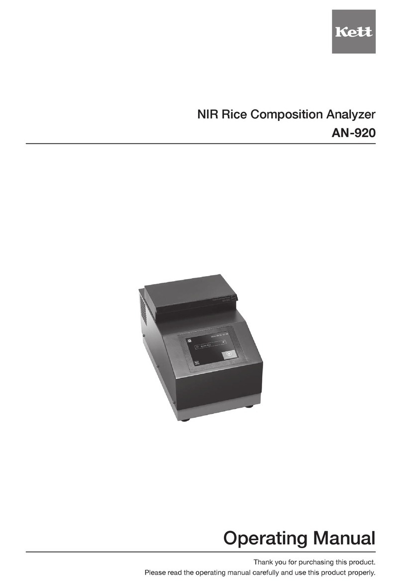
Kett KB-270 User manual

NIR Composition Analyzer
KB-270
Operating Manual
Thank you for purchasing this product.
Please read the operating manual carefully and use this product properly.


Contents
1. For safety measurement ........................................................................4
2. Features and part names .......................................................................6
2-1. Features.................................................................................................................. 6
2-2. Parts of main unit.................................................................................................... 6
2-3. Accessories ............................................................................................................ 7
3. Specications .........................................................................................8
4. Description of operation keys ...............................................................9
5. Preparing the main unit .......................................................................10
6. Specifying measuring conditions ....................................................... 11
6-1. Selecting the sample cell (container).....................................................................11
6-2. Deciding whether to use the light shielding cover ................................................ 12
6-3. Deciding whether to rotate the rotation table........................................................ 12
6-4. Setting the sampling amount ................................................................................ 13
7. Making the calibration curve ...............................................................14
7-1. Setting the measurement range and the number of samples............................... 14
7-2. Setting the sampling times.................................................................................... 14
7-3. Preparing the samples.......................................................................................... 14
7-4. Moisture preparation............................................................................................. 15
7-5. Measuring the standard composition.................................................................... 15
7-6. Making the calibration curve (optical measurement) ............................................ 15
7-7.Correction................................................................................................................ 15
8. Measurement ........................................................................................16
8-1. Normal measurement mode ................................................................................. 16
8-2. Continuous measurement mode........................................................................... 17
8-3. Absorbance display mode .................................................................................... 17
8-4. Printer output ........................................................................................................ 17
9. Zero-adjustment ...................................................................................18
10. Setup......................................................................................................19
11. Maintenance..........................................................................................27
11-1. Replacing light source lamp.................................................................................. 27
11-2. Replacing fuses .................................................................................................... 28
11-3. Consumable parts................................................................................................. 28
11-4. Inspection ............................................................................................................. 28
12. Error display ......................................................................................... 29
<Remarks>.................................................................................................................... 30

4
● Donotusetheunitinaplacewhereexplosive,inammablegas,orliquidsubstanceexists.
Otherwise,itmaycauseexplosion,re,orelectricshock,etc.
● Neverperformmeasurementsonexplosivematerials.
Otherwise,itmaycauseexplosionorre,etc.
● Neverperformmeasurementsontoxicmaterials.
Otherwise,itmaycauseenvironmentalcontamination.
● Donotuseotherthanratedpowersupplyvoltage.
Ifovervoltageisapplied,theunitwillbeheatedanditmaycausemalfunction,re,orelectricshock.
● Makesuretogroundthepowercable.
Withthe2Poutlet,useaconversionplugtoground.
Inthecaseof3P,itwillbeautomaticallygrounded.Ifnotgrounded,itmaycausereorelectricshock.
● Ifanyofthecablesincludingthepowercableisdamaged(broken),donotuseit.
Otherwise,itmaycausereorelectricshock,etc.Forpurchasingthespareparts,pleasecontactthe
vendor.
● If you see fire coming from the unit or notice smoke, an odd smell, or any other sign of abnormal
functioning,turnoffthepowerandremovethepowerplugfromtheoutlet,ortakewhatevermeasures
thatwouldbeappropriatetodealwiththeproblem.Otherwise,itmaycausereorelectricshock,etc.
● Donotattempttodisassembleormodifytheunit.
Otherwise, it may cause malfunction, fire, or electric shock, etc. If you believe the unit may be
malfunctioning,pleasecontactthevendor.
● Donotallowtheunittocomeincontactwithwater.
Thisunitisnotwaterproof.Donotallowwaterorotherliquidstogetintotheunit'senclosureasthismay
lead to electric shock or malfunction.
ImproperuseoftheNIRCompositionAnalyzerinviolationofthefollowingsafetynotesmayresultindeath,injury
ordamagetopropertyduetore,etc.Whilethesafetyoftheproducthasbeengivenconsiderableattention,read
the precautions in the operating manual and use the instrument properly.
■Observe the safety precautions.
Read the precautions noted in the operating manual.
The safety measure of the unit may be impaired if instructions are ignored during use.
■Do not use if broken.
Ifyoususpectaproblemormalfunctionintheunit,makesuretocontactthevendor.
■Meaning of warning symbols
In order to prevent damage resulting from erroneously operating the equipment, the following symbols are
indicated in the operating manual and on the product. These symbols have the following meanings.
CautionSymbols ProhibitionSymbols SymbolsRequiringUserAction
1. For safety measurement
Warning Failuretoobservetheseitemsmayleadtodeathorinjurytotheuser.
Caution Failuretoobservetheseitemsmayleadtoinjurytotheuserordamagetoproperty.
Note Items which the user should be aware of in order to use the unit safely.
Fire hazard Burn hazard Electric shock hazard
Prohibited
Do not
disassemble
Donotexpose
to water
Required
action
Disconnect plug
from electrical
outlet
Grounding
Warning
Burn hazard Electric shock hazard

5
● Donotdamage,heat,orplaceheavyobjectonthepowercableorconnectors.
Otherwise,itmaycausereorelectricshock,etc.
● Whenconnectingwithotherdevices,rst,turnoffthepowerofeachunit.
● Donotconnect/disconnectthepowerplugwithwethands.Otherwise,itmaycauseanelectricshock,etc.
● Inthemaintenancework,removetheplugfromtheoutletforsafety.Otherwise,itmaycauseanelectricshock.
● Todisconnecttheplugorconnector,makesuretoholdtheplugorconnector,nottopullonthecable.
● Donotdirectlylookattheblinkinglightoftheunit.
● Iftheglasspartoftheunitisbroken,carefullydisposeoftheglassfragmentsandcontactthevendor.
● Preventtheaccidentswhenmeasuringhazardousmaterials.
Operating environment for safety use
This product is designed to be used safely in the following conditions.
Make sure of the operating environment before use.
● Indooruse
● Altitude:upto2000m
● Temperature:5to35°C
● Relativehumidity:environmentaltemperatureupto31°C,max.80%;at35°C,max.65%
● Powersupplyvoltageuctuation:within10%ofnominalvoltage
● Transientovervoltage:withintheOvervoltageCategoryII(conformstoIEC60664-1:2007)
● PollutionDegree2(conformstoIEC60664-1:2007)
Installation and storage
● Avoid using or storing the unit in a location where it would be exposed to excessively high or low
temperatures,highlevelsofhumidity,directsunlight,electromagneticinterference,corrosivegases,or
large amounts of dust.
● Placetheunitonaatandstablesurfacewhereitwillnotbesubjectedtosignicantvibrationduringuse.
● Whenmovingtheunit,nevertiltitanymorethannecessary.
● Takecarenevertodroporbumptheunitorotherwiseallowittobesubjectedtostrongshocksorthe
applicationofexcessiveforce.
● Whenremovingthepowercableorothercables,neverpullonthecordorcableandinsteadholdthe
plug or cable connector.
● Usethesuppliedpowercableandmakesuretoconnecttotheprotectiveearth.
● Donotinstalltheunitinaplacewherehandlingthepowercableandconnectorsorturningthepower
switchismadedifcult.
● Installtheunitatleast10cmawayfromthewallssothattheventilationopeningsprovidedontherear
of the unit are not blocked.
● When theunit is nottobe usedoveran extendedperiod oftime,turn off thepower andremovethe
power plug from the outlet.
● Make sure to clean and remove the dust form the electrical outlet and the power plug regularly. It
prevents the tracking phenomenon.
● Placethesamplecellswithgreatcare.Otherwise,itmaycausedamagetothesamples,environmental
contaminationorinjuryincaseofearthquake.
Cleaning
● Tocleanthesurfaceoftheunit,wipeoffusingasoftdrycloth.
● Donotuseabrasivedetergentsuchaspaintthinnerorbenzenewhencleaningthisproduct.
● If measurement sample such as powder, grains, or dust gets into gaps between rotation table,
remove it to prevent malfunction.
Caution
Burn hazard Electric shock hazard

6
2. Features and part names
2-1. Features
This unit is a lter spectroscopy reection type composition analyzer applying the near-infrared
spectroscopy technology. It uses the lter of six wavelengths and one wavenumber for common
reference available for various composition measurements. It measures the near-infrared
absorption of six wavelengths of the measuring object, and converts the obtained data to the
composition. The multiple compositions (four compositions) can be measured.
2-2. Parts of main unit
<Front>
<Rear>
Power switch
Fuse holder
Power supply connector
Printer port
LAN port USBportVentilation opening
Light shielding cover (accessories are attached)
Rotation table
Measurement
window
Display and operation
50
1K50
山路を登りながら

7
2-3. Accessories
Power cable
Zero-adjustmentplate
Light shielding cover
PC software
operating manual
Petri dish (90 mm)
(Sample cell)
Sample cell holder
(forPetridish,90mm)
Spare fuse
Operating manual
(this document)
PC software
USBcable:VZC61
Using the supplied PC software, various
operationssuchaszero-adjustment,
measurement,settingthecalibrationcurve,
devicesetting, andmaintenancecanbe
performed. For communication, USB and
LAN are available.
* KB-270 is not equipped with the function to
create the calibration curve. The supplied PC
software is required to create the calibration
curve.

8
3.Specications
Measurement method :Near-infraredreection(lterspectroscopy)
Light source : Tungstenlamp(lifetime:20,000hours)
Measuring diameter : approximatelyø25mm
Number of wavelengths :7(sixwavelengthsandonewavenumberforcommon
reference available for various composition measurements)
Channel number : 50(1channelx4compositionssimultaneousmeasurement)
I/Oconnector : USB,LAN,Printeroutput
Display format :Organic EL
Display content :Channelnumber,Channelname,Composition,Absorbance
Operating temperature range : 5to35°C(nocondensation)
Power supply : 100-120VAC/220-240VAC(50/60Hz)
Power Consumption :50W
Dimensions and weight : 415mm(W)×370mm(D)×230mm(H),12kg
Maximumsamplingamount :2kg
Maximumdiameterofsample : 150 mm (when using rotation table)
Accessories :
Petridish90 mm(samplecell),SamplecellholderforPetri
dish90mm,Zero-adjustmentplate,Sparefuse,Powercable
POC03,Lightshieldingcover,USBcable,Operatingmanual,
PCsoftware,PCsoftwareoperatingmanual
Options :Printerset(Printer:VZ-800,Printercable:VZC54,papers,AC
adapter,andACcordincluded)

9
4. Description of operation keys
Operation keys Description
[MENU]key Usedforsettingupandmakingacalibrationcurve.
[ENTER]key Usedtodeterminethecurrentlyselecteditem.
[MEA.]key Usedformeasurement.
[TABLE]key UsedtosetON/OFFoftherotationtable.
[ZERO]key Usedforzero-adjustment.
[EXIT]key Usedtoexittheoperation.
[MODE]key Usedtoselectthemeasurementmode.
[CH]key Usedtochangethechannel.
[⬆]/[⬇]keys Usedtoscroll(up/down)thedisplay.
Numeric keypad Usedforenteringvaluesorcharacters.
[clear]key Usedforcancellingenteredvaluesorcharacters.

10
5. Preparing the main unit
* Clean the measurement window. If it is not clean, measurement may not be performed correctly.
* Whenclosing/openingthelightshieldingcover,becarefulnottopinchthengers.
* Be careful of protrusion provided on the top plane or edges of the main unit. Otherwise, it may
cause an injury, etc.
⑤Turn on the power switch.
Turn on the power switch located at the rear of the unit.
⑥Warm up the unit.
When the unit is powered on, the rotation table will
automatically start rotating to warm-up. At the same
time,amessage"SETTHESTDPL."willbedisplayed.
Setthezero-adjustmentplateifitwasnotsetinstep(4).
When the warm-up is done (after 5 to 6 minutes), the
indication "WARMING UP" turns off and the zero -
calibration screen will be displayed.
⑦Perform zero-adjustment.
Press the [ENTER] key to execute zero-adjustment.
Thezero-adjustmentwillproceedwhiledisplaying
the absorbance in real-time. When the calibration is
completed,theinitialscreenwillberestored.
* If the power is cycled, repeat the operation from step (6).
Make sure that the zero-adjustment plate is set.
W A R M I N G U P
S E T T H E S T D P L .
Z E R O ▶
X 1 0 . 0 0 0 1
X 2 −0 . 0 0 0 1
X 3 0 . 0 0 0 2
X 4 0 . 0 0 0 3
X 5 −0 . 0 0 1 2
X 6 0 . 0 0 0 8
Z E R O
X 1 0 . 0 0 0 0
X 2 −0 . 0 0 0 2
X 3 0 . 0 0 0 1
X 4 0 . 0 0 0 2
X 5 −0 . 0 0 0 1
X 6 0 . 0 0 0 3
0 1
1…2…
ーーーーー ーーーーー
3…4…
ーーーーー ーーーーー
①Install the main unit.
Installtheunitinaplacewheredirectsunlightisavoidedandnotbesubjectedtosignicantvibration.
②Attach the light shielding cover.
Attach the light shielding cover by inserting the columns provided on the top surface of the unit into the mounting
holes on the cover.
③Connect the power cable.
Connect the main unit and the power cable.
Plugintothesocket,andmakesuretoground.
④Attach the zero-adjustment plate.
Openthelightshieldingcover,andsetthezero-adjustmentplateontotherotationtableoftheunit.Then,close
the cover.

11
6. Specifying measuring conditions
1. Petri dish (composition in general)
Beans, etc.
For uneven grains or large grains
• It is reusable.
•
A cover can be used. It will reduce the moisture change while storing the sample.
• The light shielding cover can be used.
• A measurement using the rotation table is possible.
•
Cleananddryisrequiredateverymeasurementtopreventmixtureofsamples.
• Carefully handle so as not to break.
* Use an accessory or following Petri dish:
Fine-marked Petri dish, 90 or 150 (TGK)
2. Plastic bag (only for moisture)
Flour and papers, etc.
For powders, small grains or sheets
• Thesamplecanbesealed,anditwillreducethemoisturechangewhile
storing the sample.
• The light shielding cover of the unit may not be used.
• The rotation table may not be used.
• Disposeeverytimetopreventmixtureofsamples.
• Use the same thickness and material of the plastic bag in making
calibration curve and performing actual measurement.
• Inordertoachieveprecisemeasurement,avoidmeasuringthegussetor
overlappedpartand,keepthemeasuringsurfacenotwrinkled.
* The following plastic bag is recommended:
Material: PE (polyethylene), PP (polypropylene), PE/PA (polyethylene/polyamide)
Thickness: 0.05 mm or more
* When measuring other than moisture, the measurement error tends to occur
depending on the light absorption characteristics of the plastic bag.
3. Polyethylene sheet (only for moisture)
Rice ball, boiled noodle, and
uncooked noodles, etc.
For large solid that may taint the measurement window
• Disposeeverytimetopreventmixtureofsamples.
• Usethesamethicknessandmaterialofthepolyethylenesheetinmaking
calibration curve and performing actual measurement.
• In order to achieve precise measurement, avoid measuring the
overlapped and keep the measuring surface not wrinkled.
*
The following polyethylene sheet is recommended:
Material: PE (polyethylene), PP (polypropylene), PE/PA (polyethylene/polyamide)
Thickness: 0.05 mm or more
* When measuring other than moisture, the measurement error tends to occur
depending on the light absorption characteristics of the plastic bag.
4. Direct placement (composition in general)
Non-fried noodle or rice crackers, etc.
For large solid that will not taint the measurement window
•
Cautionisrequirednottoscratchortaintthemeasurementwindow.
• The sample should not fall off or spilled when it is set.
6-1. Selecting the sample cell (container)
Accordingtotheformofthemeasuringsample,selectasamplecellfromfourtypeslistedinthefollowing.
* Make sure that the selected one fully covers the measurement window. Also, use the same one in making
calibration curve and actual measurement.
* When measuring the liquid sample, be careful not to spill on the unit.

12
Rotationicon→
6-3. Deciding whether to rotate the rotation table
Whenmeasuringsamplesofdifferentcompositionsorunevenforms,rotatingthesamplewillhelp
improve averaging accuracy of the measurement values.
Eachtimethe[TABLE]keyispressed,therotationofthetablecanbeenabledordisabled.
0 1
1…2…
ーーーーー ーーーーー
3…4…
ーーーーー ーーーーー
0 1
1…2…
ーーーーー ーーーーー
3…4…
ーーーーー ーーーーー
* Some sample may not be rotatable. (ex. A large sample, or when the sample moves, etc.)
* Use caution for falling-off of the samples during rotation.
* When rotating the table using a 90 mm of Petri dish, use the sample cell holder. Also, use the light shielding
cover to prevent falling-off.
* When using the polyethylene sheet, prevent the sheet from being caught by the rotating table. Also, use the
light shielding cover to prevent falling-off.
6-2. Deciding whether to use the light shielding cover
Thelightshieldingcovercanavoideffectsfromexternallight.
Itispreferabletousethecoverinordertoavoidexternallight.
* Perform measurement closing the light
shielding cover if possible.
* The cover may not be usable depending on the
sample cell or sample form. In the case of not
using the cover, it can be removed.

13
6-4. Setting the sampling amount
Put the sample in the sample cell selected in section 6-1 and measure the absorbance to determine
the sampling amount.
* If the sampling amount (sample height) is not consistent, it may affect the absorbance.
* When not using the light shielding cover, determine the sampling amount under the same condition of
external light as measurement.
* Use the same amount in making calibration curve and measurement.
①Set the absorbance measurement mode.
Enter the absorbance measurement mode by pressing
the[MODE]key.(→8.Measurement(P.16))
Immediatelybeforeperformingthisoperation,itis
recommendedtoperformzero-adjustment.(→9.Zero-
adjustment(P.18))
②Measure the absorbance.
Use the sample cell selected in section 6-1. Set the
sample to cover up the measurement window and
measure the absorbance.
③Observe the change of absorbance.
Asthesampleisgraduallyraised,theuctuationofdisplayedabsorbance,X1toX6,willbecomestable
at a point where the near-infrared pass-through is stopped. Consider the sampling amount at this point
as "absorbance saturated sampling amount". If the sampling amount is sufciently prepared, set the
samplingamountmorethanthe"absorbancesaturatedsamplingamount".
* Refer to P.30 <Remarks>, if the absorbance saturated sampling amount cannot be prepared.
0 1
X 1 0 . 0 0 0 0
X 2 −0 . 0 0 0 2
X 3 0 . 0 0 0 1
X 4 0 . 0 0 0 2
X 5 −0 . 0 0 0 1
X 6 0 . 0 0 0 3
0 1
X 1 0 . 1 9 2 7
X 2 0 . 0 2 0 1
X 3 0 . 2 8 0 4
X 4 0 . 1 9 2 6
X 5 0 . 2 6 2 2
X 6 0 . 3 1 2 0
Sampling
amount
Sampling
amount
Sampling
amount
Near-infraredNear-infrared
Sampling
amount
Absorbance
While the near-infrared from the bottom
passes through the sample, the displayed
valuewillcontinuetouctuate.
Ex.)
Ex.)
When the sample height is raised, there will be a point
where the near-infrared pass-through is stopped.
Then, the value will become stable.
Con sider t h e p oint
where only the last 2
digits of absorbance
fluctuate as the
absorbance saturated
sampling amount.
X1 0.2985.....0.2994
X2 0.0357.....0.0362
X3 0.3982.....0.4006
X4 0.2887.....0.2907
X5 0.3752.....0.3774
X6 0.4320.....0.4349
No more change in raising the height of sample
X1 0.1927.....0.2695.....0.2897
X2 0.0201.....0.0286.....0.0334
X3 0.2804.....0.3687.....0.3914
X4 0.1926.....0.2614.....0.2820
X5 0.2622.....0.3460.....0.3685
X6 0.3120.....0.4021.....0.4250
Ex.)

14
7. Making the calibration curve
7-1. Setting the measurement range and the number of samples
Setthecompositiontomeasureandthenumberofsamplesrequiredformakingcalibrationcurve.The
sampleswithdifferentcompositionpercentagesthatfullycoversthemeasurementrangearerequired.
* When measuring the moisture, if samples with different moisture cannot be prepared in the regular
composition control process (drying or adding water), refer to section 7-4. Moisture preparation.
* The larger number of samples will make better reliability of the calibration curve. It is recommended to
preparemorethanvesamples.Atleastthreesamplesarerequiredtomakeacalibrationcurve.
* The measurement result obtained from outside of the composition range used in making calibration curve
will not be reliable.
* The composition of the samples should be balanced in the measurement range.
● Necessityofcalibrationcurve
The NIR Composition Analyzer measures the near-infrared absorption of the measuring object,
andconvertstheobtaineddatatothepercentageofcomposition.Therefore,aconversionformula
thatcalculatestheactualcompositionfromthenear-infraredabsorptionisrequired.Thisiscalled
"calibrationcurve".Thecalibrationcurvediffersdependingonthemeasuringobject.Therefore,itis
requiredtomakecalibrationcurveperobjectinadvance.Thisunitiscapableofmakingcalibration
curve easily using the supplied PC software.
7-2. Setting the sampling times
Set the sampling times per composition.
Generally,threetovetimesisappropriate.However,iftheconsistencyofthesampleislow,seta
larger number.
7-3. Preparing the samples
The sampling amount set in section 6-4 is represented as A. The sampling times set in section 7-2
is represented as B. At least the sampling amount of AxBpercompositionisrequired.Prepare
enough samples to be used in the measurement of standard composition (section 7-5) as well.
Composition percentage
Target composition range Higher than the maximum
composition range
to be measured
The sample for making calibration curve
should cover from 1 to 5 equally.
Lower than the minimum
composition range
to be measured
12345
Ex.)Preparing5samples
Composition percentage
50 g x 4 times + 20 g =
220 g
50 g x 4 times + 20 g =
220 g
50 g x 4 times + 20 g =
220 g
50 g x 4 times + 20 g =
220 g
50 g x 4 times + 20 g =
220 g
Ex.)SamplingamountA............................................ 50g
Sampling times B......................................... 4 times
For measurement of standard composition ......... 20g
* In this case, 220 g of sample is required per composition.
In total of 5 different composition samples, 1,100 g is required.

15
7-4. Moisture preparation
Inthemeasurementofmoisturecontent,ifsamplestofullycoverthemeasurementrangecannot
bepreparedintheregularmoisturecontrolprocess(dryingoraddingwater),preparethesamples
by moisture preparation. To derive a sample with different moisture by moisturising or drying a
source sample is called "moisture preparation". There are various ways to change the moisture
content, such as spraying water using an atomizer or drying the high moisture content sample.
Make samples with different moisture by selecting an optimum method according to the measuring
object.Also,whensamplesare made bymoisture preparation,it isrecommended to wait veto
sevendaysuntiladdedwateriswellsoakedtoobtainbetterconsistencyofmoisture.Then,perform
measurementfollowingthenextsection"7-5Standardcompositionmeasurement"and"7-6Making
thecalibrationcurve(opticalmeasurement)".
7-5. Measuring the standard composition
Precisely measure the composition of a part of each sample.
(Applytheover-dryingmethod,etc.forthemoisturecontent.)
Then,considertheobtaineddataasthestandardcomposition.
* As the over-drying method, the ofcial method or a measurement using an infrared moisture analyzer is
available.
* Note that the sample cannot be reused in the standard composition measurement.
* If thesamplingamountisnotsufcient or when performing the standardcompositionmeasurementand
actual measurement using the same samples, perform the optical measurement described in "7-6 Making
thecalibrationcurve(opticalmeasurement)"rst,thenmeasurethestandardcomposition.
7-6. Making the calibration curve (optical measurement)
Setthemainunit.(→5.Preparingthemainunit(P.10))
UsethesuppliedPCsoftwaretocreateacalibrationcurve.
Fordetails,refertothePCsoftwareoperatingmanual(4-1.Makingthecalibrationcurve).
Per form measurement under the same condition in making calibration curve and regular
measurement.
7-7. Correction
Setting the offset value and tilt correction value will enable correction of measurement value.
* no. how to set the offset value and tilt correction value, refer to the items described in "Setting the channel
parameter" (P.20) or the PC software operating manual (4-2. Correction).
Composition value (displayed composition) after correction =
Composition value before correction x Tilt correction value + Offset value

16
8. Measurement
Measurethesampleinthesamemeasurementconditionasmakingcalibrationcurve.(→6.Setting
the measurement conditions (P.11))
* Itisrecommendedtoperformzero-adjustment.(→9.Zero-adjustment(P.18))
<Step 1>
● Selectthechannelnumber.
Intheinitialscreen,selectthechanneloperating[CH.],[⬆],[⬇],and[ENTER]keys.
[Channel selection screen]
Whenchangingthemeasurementchannel,orduringsetup,thefollowingwillbedisplayed.
0 1 F L O U R 1234 ▶
0 2 F L O U R 2 12 34
0 3 C O R N 1 12 −4
0 4 C O R N 2 1−−−
0 5 B U T T E R 1 2 3 −
0 6 −−−−
0 7 −−−−
0 8 −−−−
[Presenceofcoefcientofeachcompositionanddisplaysetting]
Icon Coefcient Display setting
1234 Present ON
1234 Present OFF
−Absent Setting not available
* Whenchangingthemeasurementchannel,thechannelthathasnocoefcientortheonewhosedisplay
setting of all four compositions is set OFF cannot be selected.
<Step 2>
● Selectthemeasurementmode.
Pressthe[MODE]keyandselectthemeasurementmode.
Therearethreemodes:normalmeasurementmode,continuousmeasurementmode,and
absorbance display mode.
8-1. Normal measurement mode
Followingstep1and2,selectthenormalmeasurementmode.
0 1 F L O U R
1…M O I S T U R E 2…P R O T E I N
1 3. 3 8. 8
3…C O M P 3 4…C O M P 4
1. 4 7 6. 1
Setthesampletocoverupthemeasurementwindowandpressthe[MEA.]key.Thecomposition
will be displayed after measurement.
* Setthenumberofdisplaydigitsandtheaveragingtimesasrequired.(→Settingthechannelparameter(P.20))

17
<Printoutexample>
8-2. Continuous measurement mode
Followingstep1and2,selectthecontinuousmeasurementmode.
0 1 F L O U R
1…M O I S T U R E 2…P R O T E I N
1 3. 3 8. 8
3…C O M P 3 4…C O M P 4
1. 4 7 6. 1
Set the sample to cover up the measurement window.
The continuously measured composition will be displayed.
* Setthenumberofdisplaydigitsandsmoothingvalueasrequired.(→Settingthechannelparameter(P.20))
8-3. Absorbance display mode
Followingstep1and2,selecttheabsorbancedisplaymode.
0 1 F L O U R
X 1 0 . 5 7 4 7
X 2 0 . 1 9 7 6
X 3 0 . 5 1 5 4
X 4 0 . 4 1 8 1
X 5 0 . 1 9 8 4
X 6 0 . 1 2 9 6
Set the sample to cover up the measurement window.
The continuously measured absorbance will be displayed.
* Setthesmoothingvalueasrequired.(→Settingthechannelparameter(P.20))
8-4. Printer output
The Printer VZ-800 is available as an option.
The normal mode measurement data can be printed.
①Make sure that the power of KB-270 and the printer are turned off.
②Connect the printer cable VZC54 (designated one) to the
printer output port provided on the rear of the main unit of KB-
270.Then,tightenthescrew.
③Connect the printer cable VZC54 (designated one) to the input
connectorprovidedonthebottomoftheprinter,andtightenthe
screws.
④Turn on the power of KB-270 and the printer.

18
9. Zero-adjustment
● Whatiszero-adjustment?
If errors occur in the measurement results due to light source consumption or other
causes,readtheabsorbanceobtainedfromreectiononthezero-adjustment plate.
The measurement result will be stabilized by setting the absorbance as zero.
Make sure to perform this operation when making calibration curve or in the regular
measurement as well.
Also,thezero-adjustmentisrequiredafterthepoweristurnedon.
Ifperformingzero-adjustmentwithoutcyclingthepower,operatethefollowing:
①Attach the zero-adjustment plate.
Openthe lightshielding cover,and setthezero-adjustment plateontothe rotation table of the
unit.Then,closethecover.
②Perform zero-adjustment.
Pressthe[ZERO]key.Thezero-adjustmentscreenwillbedisplayed.
Z E R O ▶
X 1 0 . 0 0 0 1
X 2 −0 . 0 0 0 1
X 3 0 . 0 0 0 2
X 4 0 . 0 0 0 3
X 5 −0 . 0 0 1 2
X 6 0 . 0 0 0 8
Pressthe[ENTER]key.Thezero-adjustmentwillbestarted.
Whenthezero-adjustmentiscompleted,theinitialscreenwillberestoredautomatically.
Intheregularmeasurementmode,thepreviousmeasuredvaluewillbedisplayed.
0 1 F L O U R
1…M O I S T U R E 2…P R O T E I N
1 3. 3 8. 8
3…C O M P 3 4…C O M P 4
1. 4 7 6. 1
* The zero-adjustment is to calibrate the absorbance obtained by measuring the zero-adjustment plate to
zero. It does not make the composition measurement value zero.

19
10. Setup
Each setting can be checked or changed.
①Pass code input
Pressthe[MENU]key,andenterthepasscode.
Atthetimeofshipment,"9999"isset.
P A S S C O D E ?
ーーーー
②Selecting each setting
The menu screen will be displayed.
1 . C H P A R A M E T E R ▶
2 . C H D U P L I C A T E
3 . C H R E S E T
4 . C O M S E T T I N G
5 . P A S S C O D E
6 . X P O R T S E T U P M O D E
Highlighttheitemtosetwith[⬆]/[⬇]key.
Pressingthe[ENTER]keywillenablethesetting.
Set the item referring to the corresponding pages.
Display Contents Page
1 . C H P A R A M E T E R ▶Setting the channel parameter P. 2 0
2 . C H D U P L I C A T E Duplicating a channel P. 2 3
3 . C H R E S E T Initializing the channel P. 2 4
4 . C O M S E T T I N G Communication setting P. 25
5 . P A S S C O D E Setting the pass code P. 2 6
6 . X P O R T S E T U P M O D E Setting XPORT P. 2 6
* To cancel the setting during operation, press the [EXIT] key. Then, the initial screen will be
restored.
* The set item is kept until it is changed even after the power is turned off.

20
Step
Display Operation
①
1 . C H P A R A M E T E R ▶
2 . C H D U P L I C A T E
3 . C H R E S E T
4 . C O M S E T T I N G
5 . P A S S C O D E
6 . X P O R T S E T U P M O D E
● Selectthechannelparameter.
Movethecursorinthemenuscreento[1.CHPARAMETER]
with [⬆]/[⬇]key.Then,pressthe[ENTER]keytoset.
②
1 . C H P A R A M E T E R
0 1 F L O U R 1234 ▶
0 2 F L O U R 2 12 34
0 3 C O R N 1 12 −4
0 4 C O R N 2 1−−−
0 5 B U T T E R 1 2 3 −
0 6 −−−−
0 7 −−−−
● Selectthechanneltoset.
Move the cursor to the desired channel with [⬆]/[⬇]key.
Then,pressthe[ENTER]keytoselect.
③
1 . C H P A R A M E T E R
0 1 F L O U R
C H N A M E ◀F L O U R ▶
S M O O T H I N G 1
M E A S N T 1
C O M P . P A R A M E T E R
O K ▶
C A N C E L ▶
● Enterthechannelname.
Ifthealreadyentered,movethecursortotherightend[▶],
andpressthe[ENTER]key.Thechannelnamewillbeset.
<To enter or edit>
Move the cursor using the [EXIT] and [ENTER] keys.
Input the channel name from the 1st character using t he
numeric keypad moving the cursor one by one with the [Enter]
key. Up to 8 characters can be entered. After input is done,
move the cursor to the right end [▶] using the [ENTER] key.
Then, press the [ENTER] key again to set.
④
1 . C H P A R A M E T E R
0 1 F L O U R
C H N A M E 0
S M O O T H I N G ◀1▶
M E A S N T 2
C O M P . P A R A M E T E R
C A N C E L ▶
● Enterthesmoothingvalueofcontinuousmeasurement.
Select the smoothing value (0 to 5) using [⬆]/[⬇]key,and
pressthe[ENTER]keytoset.
A channel identification. It will
be displayed when changing
thechannel,ordisplaying
measurement value.
1. Channel name (8 alphanumerics)
⇒step (3)
2. Smoothing value of continuous
measurement (0 to 5)
It is set to minimize the variation of
the displayed value when observing
the time variation in the continuous
measurement mode or absorbance
display mode. If a large value is set
to the smoothing value of continuous
measurement,asmoothchangewithout
quivering will be observed. However,
it will deteriorate the response.
Therefore, it should be avoided to set
unnecessarily large value.
⇒step (4)
The averaging times in the normal
measurement mode can be set. The
defaultis"1time".Thisunitcountone
data by averaging 6 data. Therefore,
keep the default in the regular
operation.It will help improve averaging
accuracy of the samples.
Measurement averaging times
<Once>
The requiredtime formeasurementis
approximately9seconds
<Twic e>
The required time for measurement is
approximately12seconds
3. Averaging times in normal measurement
(Default: 1 time)
■Settingthechannelparameter
Following four items can be set per channel.
* To cancel the setting during operation, press the [EXIT] key. Then, the previous screen will be restored.
⇒step (5)
Table of contents
Other Kett Measuring Instrument manuals