Enotec COMTEC 6000 ATEX GasEx User manual

Doc.-ID: COMGAS_11022020_EN
Installation and Operation Manual
Explosion-Proof O
2
/COe Analyzer System
COMTEC
®
6000 ATEX GasEx
Version: 19
for Software Version: 4.13
Doc.-ID: COMGAS_11022020_EN
Preface
Dear Customer,
Thank you for selecting COMTEC
®
6000 GasEx as your InSitu Flue Gas O
2
/ COe Analyzer System.
Since 1980 our analyzer systems have been operating in numerous applications with tens of thousands of units being produced
and shipped worldwide. ENOTEC is committed to absolute quality and performance and over time we have continuously
enhanced our products to integrate various features and functions.
In this package, the electronic unit uses the very latest Microprocessor Technology, making the SME5 electronic unit one of the
most advanced and up-to-date monitoring units, permitting you to reduce your maintenance & fuel costs and to achieve
increased measuring accuracy with operational reliability.
ENOTEC probes include the zirconium oxide sensor which has a gas-tight seal made by using a special process and technique
developed by ENOTEC. This leads to a considerably increased service life compared to "glued or cemented" sensors that have
a tendency to leak or crack during operation.
All ENOTEC instruments are thoroughly tested in the factory and are subject to a strict ISO 9001 and internal quality assurance
procedure. Therefore, with correct installation, the operation of the COMTEC
®
6000 GasEx InSitu analyzer system is
straightforward and user friendly and will provide you with many years of trouble free operation with perfect measuring results.
Symbols used in this Manual
All symbols listed beneath, attached to the analyzer or noted in this manual show important information as well as safety
instructions for installation, operation and maintenance, to protect the personnel and the equipment.
Warning
Follow all instructions in this manual
Consider Following Information
Points out important information which must be
noted before execution
Warning hot Surface
Warns of danger of burns which could occur from
hot system parts
Info
Contains further detailed information
Caution
Warns of risks by destroying the system or its
components or its functionality
Ground earth electrical protection
The content of this manual is protected by copyright. Alterations and errors reserved.
Safety Instruction
This system is operated with line voltage. If covers are removed during which line voltage is still connected, an electric shock
hazard will occur.
Only well trained and authorized personnel are allowed to conduct work on this system. Personnel have to understand all
precautions, safety instructions, installation and maintenance instructions in this manual. The trouble free and safe operation of
this system requires safe transportation, professional storage, installation, operation and maintenance. Furthermore, all local
safety requirements have to be considered.
This system may not be used in the vicinity of combustible gases as parts of the system may cause a risk of explosion.
The device may only be put into operation if the enclosed instructions have been fully understood.
This manual is also available in other languages on request

Installation and Operation Manual - COMTEC
®
6000 ATEX GasEx Table of Contents
Doc.-ID: COMGAS_11022020_EN 3
Table of Contents
1System Description 4
System Overview......................................................4
1.1
Measuring Principles ................................................6
1.2
Explosion Protection.................................................6
1.3
Intended Use.............................................................6
1.4
Safety Hazards .........................................................6
1.5
Disruption of the Process..........................................6
1.6
Storage instructions..................................................6
1.7
Name Plates .............................................................7
1.8
ATEX Certification - Probe........................................7
1.9
ATEX Certification - Electronics .............................14
1.1
2Installation 31
Installation Requirements for electronic unit ..........31
2.1
Installation of probe signal cable FEP-0007/8........32
2.2
Access to the terminals...........................................33
2.3
Wiring diagrams of COMTEC 6000 GasEx (SME-5D
2.4
and EX probe).........................................................34
Ferrite Sleeves........................................................35
2.5
Terminal connections of the COMTEC 6000..........35
2.6
Installation of the probe ..........................................36
2.7
Mounting of the Counter Flange at the Duct ..........36
2.8
Adjustment of the Probe Filter Head V-Shield........37
2.9
Mounting the protection tube at the flange.............37
2.10
Insulation with cooling protection tube....................38
2.11
Electrical connections at the Probe ........................39
2.12
Pneumatic connections at the Probe......................39
2.13
Requirements for pneumatic cable FEP-0002 .......40
2.14
Preparation of the pneumatic cable........................40
2.15
Connection of the pneumatics................................40
2.16
3Initial Operation 42
Checklist before commissioning the system ..........42
3.1
System Power Up...................................................42
3.2
Display - Probe Heating Phase ..............................42
3.3
Display - Measuring Mode......................................43
3.4
Keypad and Display................................................43
3.5
Status LEDs............................................................43
3.6
Softkey Symbols.....................................................43
3.7
System Code ..........................................................43
3.8
4Menu Overview and Explanations 44
Menu Overview - SYS-MENU.................................44
4.1
Menu Explanations - SYS-MENU...........................48
4.2
4.2.1
O
2
Measuring Ranges (Scaling)........................48
4.2.2
Limit alarm settings...........................................48
4.2.3
O
2
Sensor calibration values.............................48
4.2.4
Measuring value averaging for (O
2
and COe)...48
4.2.5
mA output on system errors (O
2
and COe) .......48
4.2.6
COe Measuring Ranges (Scaling).....................49
4.2.7
COe Sensor Calibration values.........................49
4.2.8
Time per test gas apply.....................................49
4.2.9
Delay time to process........................................49
4.2.10
Pre-purge time ..................................................49
4.2.11
Automatic Calibration (ACAL) ...........................49
4.2.12
ENOTEC REMOTE...........................................50
4.2.13
Measuring units.................................................50
4.2.14
Language..........................................................50
4.2.15
Change system code ........................................51
4.2.16
Load factory settings.........................................51
4.2.17
Set COe measurement to off/on.......................51
4.2.18
Service (Factory Service Settings)....................51
Menu Overview - System Checks.......................... 52
4.3
Menu Overview - Calibration Menu........................ 53
4.4
4.4.1
Calibration Menu - Display Overview................53
4.4.2
1-point calibration (O
2
and/or COe) (manual) ...54
4.4.3
2-point calibration (O
2
and/or COe) (manual) ...54
5Service and Maintenance 55
Exchange fuses......................................................55
5.1
Pressure and Flow rates for Test Air and/or
5.2
Reference Air ......................................................... 55
Adjusting the Flow Rate - SME 53.........................56
5.3
Position of the adjustment valves (SME-53)..........57
5.4
Adjusting the Flow Rate at the Pneumatic Unit ..... 58
5.6
Replacing the Filter Head.......................................59
5.7
Replacing the Probe............................................... 59
5.8
Replacing the Probe Inner Part..............................60
5.9
Replacing the O
2
sensor........................................ 61
5.10
Replacing the COe Sensor ....................................62
5.11
5.11.1
Seal the COe sensor guide tube.......................63
Relay Outputs / Functions and Correlation............64
5.12
6Status Messages 65
Error Messages......................................................65
6.1
Alarm Messages ....................................................67
6.2
Service Messages.................................................. 67
6.3
Heater Control Unit ................................................68
6.4
7Troubleshooting 69
ATechnical data 71
A.1
Technical Specifications SME-5D..........................71
A.2
Technical Specifications SME-53 ..........................72
A.3
Technical Specifications - Probes..........................73
A.4
Requirements for the gas supply...........................74
A.5
Dimensional drawings of the Electronics...............75
A.6
Pneumatic Unit....................................................... 77
A.7
Gas plans............................................................... 77
A.8
Dimensional drawing of probes KEX600x..............79
A.9
Protection Tube Flanges........................................80
A.10
Counter flanges......................................................80
A.11
Probe components.................................................82
A.12
Probe inner part .....................................................83
A.13
Overview of the Mounting Plate in Ex Housing......84
A.14
Mounting Plates - Safe Area Housing.................... 85
A.15
19” Rack - SME-54................................................. 87
A.16
Display Board.........................................................88
BWarranty 89
CDeclaration of Conformity – Probe 90
DDeclaration of EC conformity - Electronics 91
Index 92
System Description Installation and Operation Manual - COMTEC
®
6000 ATEX GasEx
4 Doc.-ID: COMGAS_11022020_EN
1 System Description
System Overview
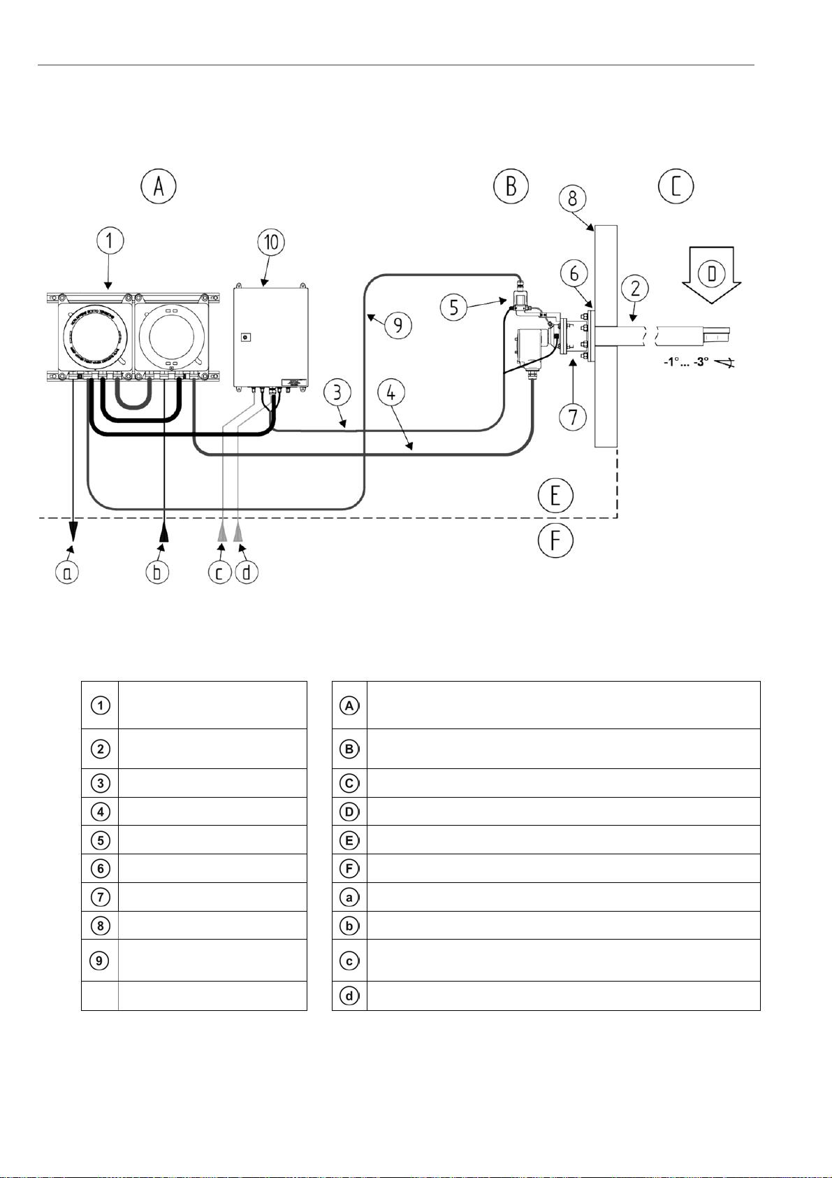
1.1
Figure 1 - System Overview with explosion proof housing and probe
Electronic unit / IP66 Hazardous Area-
Max. ambient temp.:-20°C to +55°C (-4°F to + 131°F)
In-situ measuring probe / IP66 Hazardous Area
Max. ambient temp.:-20°C to +70°C (-4°F to + 158°F)
Pneumatic cable Duct / combustion chamber
O
2
probe signal cable Flue gas direction – max. flue gas temperature 500 °C
Solenoid valve (Optional) Manufacturer supply
Counter flange (Optional) Customer supply
Isolation: Customer Output signals (analog and digital)
Duct wall Power supply
Solenoid valve control cable
(only with solenoid valve) Test gas in
Pneumatic unit / IP65 Instrument air in
Installation and Operation Manual - COMTEC
®
6000 ATEX GasEx System Description
Doc.-ID: COMGAS_11022020_EN 5
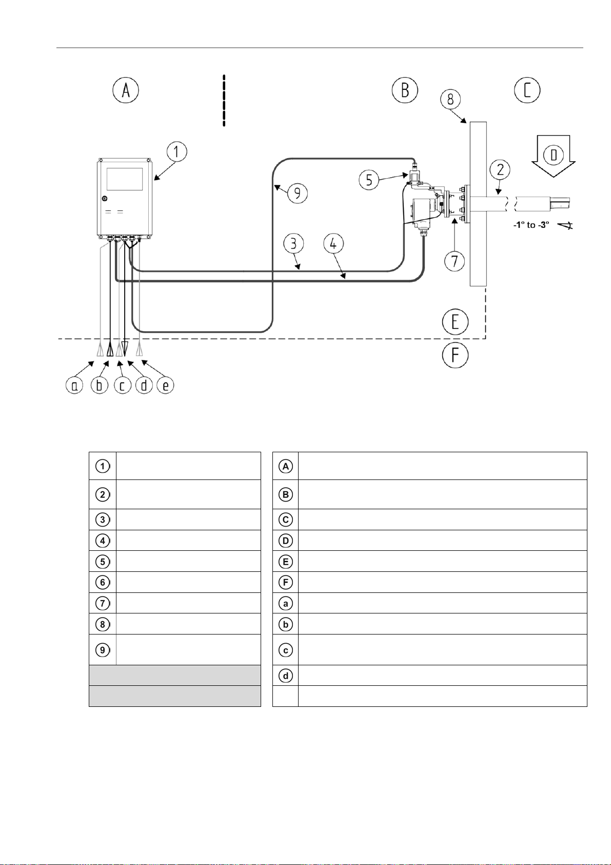
Figure 2 - System Overview with Safe Area housing
Electronic unit / IP66 Safe Area
Max. ambient temp.: -20°C to +55°C (-4°F to + 131°F)
In-situ measuring probe / IP66 Hazardous Area
Max. ambient temp.: -20°C to +70°C (-4°F to + 158°F)
Pneumatic cable Duct / combustion chamber
O
2
probe signal cable Flue gas direction – max. flue gas temperature 500 °C
Solenoid valve (Optional) Manufacturer supply
Counter flange (Optional) Customer supply
Isolation: Customer Test gas in
Duct wall Power supply
Solenoid valve control cable
(only with option solenoid valve) Instrument air in
Output signals (analog and digital)
Test air in (only with pump version of electronics)

System Description Installation and Operation Manual - COMTEC
®
6000 ATEX GasEx
6 Doc.-ID: COMGAS_11022020_EN
Measuring Principles
1.2
The COMTEC
®
6000 O
2
/ CO
e
analyzer system consists of an in-situ probe which is installed in a duct to measure
non-combustible process gases and of an electronic unit for voltage and gas supply, as well as for signal processing.
The O
2
sensor of the COMTEC 6000 is at the tip of the probe and is regulated to 800 °C and works on the zirconium
oxide principle of measurement. Here, a mV signal between the reference gas side of the sensor (inside, instrument
air 20.95% O
2
) and the measured gas side is measured, which depends logarithmically on the ratio of oxygen partial
pressures on both sides of the sensor. The mV signal is converted according to the Nernst equation into oxygen
partial pressure within the process gas, whereby the O
2
concentration is determined in the process gas. Gas-tight
separation of reference air and process gas is of particular importance.
The CO
e
sensor at the tip of the COMTEC
®
6000 probe detects combustible, gaseous molecules whereby the
measured value corresponds to the CO equivalent (CO
e
= CO equivalent). This value can be used as an indication of
the combustion efficiency. A high COe value correlates with poor efficiency because a portion of the fuel is not
completely oxidized.
The InSitu sensor is in contact with the sample gas with both electrodes. These catalytically active electrodes cause
oxidation of the non-oxidized gas molecules, so that a voltage is generated between the electrodes, which depend on
the COe concentration. Thus CO, H2 and CxHy (Hydrocarbons) can be measured.
Explosion Protection
1.3
The electronic system of COMTEC
®
6000 GasEx Analyser Systems is certified for zone 1 – 2 installations and also
the probe can be installed in zone 1 - 2 areas.
Intended Use
1.4
The COMTEC
®
6000 GasEx InSitu Analyser System is a system for measuring the concentration of oxygen and COe
in flue gases and any other non-combustible gasses. For reasons of safety and the possible occurrence of accidents,
unauthorized conversions and modifications of the system are prohibited.
Info
The minimum concentration of O
2
in flue gas should under normal process conditions, not be less than 0,5%.
If the O
2
concentration is regularly below 0,5%, we recommend the option of CSP (Cell Surface Protection) to
protect the O
2
sensor
.
Caution
Under no circumstance should the measuring probe be directly connected to the 230V main power supply, as this will
immediately destroy the probe heater element!
Safety Hazards
1.5
Warning hot Surface
During operation, the temperature of the probe filter head and of all parts exposed to flue gas is 150°C – 500°C
(302°F - 932°F). Direct contact with the hot parts for dismantling or maintenance will cause severe burns!
The probe may only be removed with heat-insulated gloves. Before removing the probe, always switch off the
supply voltage to the electronic system.
Disruption of the Process
1.6
The analyser system has to be kept in operation also in the event of the process being disrupted or if the plant is
powered off temporarily (e.g. at night or during the weekend). Frequently cooling down and heating up of the probe
results in thermal stress of the hot probe parts (heater, thermocouple and sensor) and reduces their product life.
ENOTEC will not accept any responsibility for resultant damage.
Storage instructions
1.7
ENOTEC equipment and spares are to be stored in a dry and ventilated environment. Paint fumes, silicone sprays,
etc. must be avoided in the storage environment.

Installation and Operation Manual - COMTEC
®
6000 ATEX GasEx System Description
Doc.-ID: COMGAS_11022020_EN 7
Name Plates
1.8
The name plate of the probe contains year of manufacture, probe serial number, O
2
sensor number and system order
code. The system order code contains system information which details the system test report and is supplied with
the system
SME-5D
SME-53
Figure 3 - Name plate of the electronics
Probe connection box
Figure 4 - Name Plate of the Probe
ATEX Certification - Probe
1.9

System Description Installation and Operation Manual - COMTEC®6000 ATEX GasEx
8 Doc.-ID: COMGAS_11022020_EN

Installation and Operation Manual - COMTEC®6000 ATEX GasEx System Description
Doc.-ID: COMGAS_11022020_EN 9

System Description Installation and Operation Manual - COMTEC®6000 ATEX GasEx
10 Doc.-ID: COMGAS_11022020_EN

Installation and Operation Manual - COMTEC®6000 ATEX GasEx System Description
Doc.-ID: COMGAS_11022020_EN 11

System Description Installation and Operation Manual - COMTEC®6000 ATEX GasEx
12 Doc.-ID: COMGAS_11022020_EN

Installation and Operation Manual - COMTEC®6000 ATEX GasEx System Description
Doc.-ID: COMGAS_11022020_EN 13

System Description Installation and Operation Manual - COMTEC
®
6000 ATEX GasEx
14 Doc.-ID: COMGAS_11022020_EN
ATEX Certification - Electronics
1.1

Installation and Operation Manual - COMTEC®6000 ATEX GasEx System Description
Doc.-ID: COMGAS_11022020_EN 15

System Description Installation and Operation Manual - COMTEC®6000 ATEX GasEx
16 Doc.-ID: COMGAS_11022020_EN

Installation and Operation Manual - COMTEC®6000 ATEX GasEx System Description
Doc.-ID: COMGAS_11022020_EN 17

System Description Installation and Operation Manual - COMTEC®6000 ATEX GasEx
18 Doc.-ID: COMGAS_11022020_EN

Installation and Operation Manual - COMTEC®6000 ATEX GasEx System Description
Doc.-ID: COMGAS_11022020_EN 19

System Description Installation and Operation Manual - COMTEC®6000 ATEX GasEx
20 Doc.-ID: COMGAS_11022020_EN
Table of contents
Other Enotec Measuring Instrument manuals


Popular Measuring Instrument manuals by other brands


Sequoia
Sequoia LISST-VSF user manual

Keysight Technologies
Keysight Technologies N9340B Configuration guide

Honeywell
Honeywell UDA2182 Faq

Physio Control
Physio Control TrueCPR 80596-000001 Instructions for use

Stanford Research Systems
Stanford Research Systems SR785 Brochure & specs

PCB Piezotronics
PCB Piezotronics J357B34 Installation and operating manual