Ensenior 52-357 User manual
User Manual of
Model
Notice: This user manual is applied to the models above
Ensenior 52’’ Ceiling Fan with Light Remote Control
V01
Ensenior
52-357 52-42852-338
5 Color Temps

Perfect Lighting Solution to Enhance Your Life
Ensenior
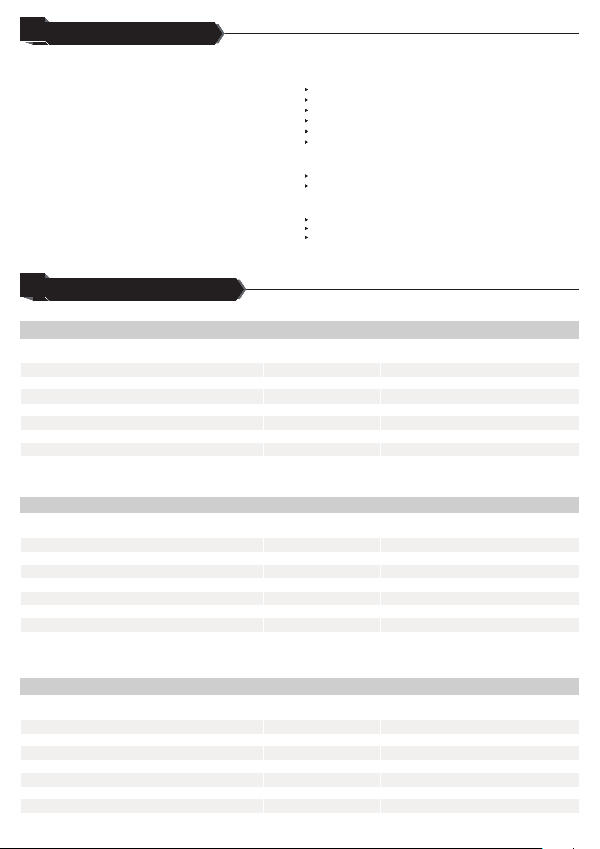
TABLE OF CONTENTS
01
PRODUCT INFORMATION
02
Product Weight
(the whole assembled fixture)
Product Height
(the whole assembled fixture)
12.26 lbs/5.56 KG
16.14 Inches
Velocity/Speed 6 levels
Wattage 35W
CFM 5938
Brightness(Lumens) 1200LM
Color Temperature 2700K/3000K/4000K/5000K/6000K
Wattage 18W
Lampshade Glass
Dimmable Yes
Efficiency(LM/W) 66.67LM/W
Color Rendering Index(CRI)
Dimming Range
80
10%-100%
10%-100%
10%-100%
Voltage 120V
Operating Temperature
The Fan The LED Light
The Whole Fixture
TABLE OF CONTENTS.............................................1
PRODUCT INFORMATION.......................................1
SAFETY INSTRUCTIONS.........................................2
PACKAGE CONTENTS.............................................4
PREPARATION...........................................................5
INSTALLATION INSTRUCTIONS........................................6
TROUBLESHOOTING.........................................................11
AFTERSALES SERVICE....................................................12
14°F to 104°F
Specific Uses
Max Angle for Angled Mount
Indoor use only (dry places)
10°
Models:52-357-1 52-357-2 52-357-3
Product Weight
(the whole assembled fixture)
Product Height
(the whole assembled fixture) 15.16 Inches
Velocity/Speed 6 levels
Wattage 35W
CFM
Brightness(Lumens) 1000LM
Color Temperature 2700K/3000K/4000K/5000K/6000K
Wattage 15W
Lampshade Plastic
Dimmable Yes
Efficiency(LM/W) 66.67LM/W
Color Rendering Index(CRI)
Dimming Range
80
Voltage 120V
Operating Temperature
The Fan The LED Light
The Whole Fixture
14°F to 104°F
Specific Uses
Max Angle for Angled Mount
Indoor use only (dry places)
10°
Models:52-338-1 52-338-2 52-338-3
Product Weight
(the whole assembled fixture)
Product Height
(the whole assembled fixture) 17.13 Inches
Velocity/Speed 6 levels
Wattage 35W
CFM
Brightness(Lumens) 1200LM
Color Temperature 2700K/3000K/4000K/5000K/6000K
Wattage 18W
Lampshade Glass
Dimmable Yes
Efficiency(LM/W) 66.67LM/W
Color Rendering Index(CRI)
Dimming Range
80
Voltage 120V
Operating Temperature
The Fan The LED Light
The Whole Fixture
14°F to 104°F
Specific Uses
Max Angle for Angled Mount
Indoor use only (dry places)
10°
Models:52-428-1 52-428-2 52-428-3
1
Installing the Hanger Bracket............................................................................6
How to Use the Balancing Kit.........................................................................12
Problem and Solution.......................................................................................11
Hanging the Fan: Assembling the Downrod and the Motor.....................6
Wiring.......................................................................................................................7
Attaching the Fan Blades...................................................................................8
Assembling the Light Kit....................................................................................8
Remote Control Instructions.............................................................................9
Contact Us...........................................................................................................13
Warranty..............................................................................................................13
Customer Service..............................................................................................12
12.10 lbs/5.49 KG
11.68 lbs/5.3 KG
6212
6851

SAFETY INSTRUCTIONS
03
30 Inches
2
7.5 Feet
All electrical connections must be in accordance with local and National Electric Code (N.E.C.) standards and ANSI/NFPA 70.
Consult a qualified electrician if you are unfamiliar with proper electrical wiring connections.
Before you start installing this ceiling fan, disconnect the power supply by turning off the circuit breaker.
Do not alter, re-locate or remove wiring when nothing goes wrong with the product.
Double-check all connections and screws to be sure they are tight and correct.
Verify whether the supply voltage is correct by comparing it with the product information.
Keep combustibles and other materials that may burn away from this product.
The maximum operating temperature is 104°F. Do not operate the fixture at temperatures higher than that. (The minimum is 14°F).
RISK OF ELECTRIC SHOCK
WARNING
RISK OF FIRE
To reduce the risk of fire, electrical shock, or personal injury, mount the fan directly from the support structure of the building by connecting the
wires to the approved electrical outlet box, and use only the hardware supplied. If you prefer an outlet box to install this ceiling fan, the outlet box
should be marked “acceptable for fan support” of 35 lbs (15.88 kg) and use the mounting screws provided with the outlet box. Plastic outlet boxes
are not recommended for ceiling fan installation. Most outlet boxes commonly used for the support of lighting fixtures are not acceptable for fan
support and may need to be replaced, please consult a qualified electrician. Failure to do this can result in serious injury or death.
If the ceiling is plasterboard or a hollow wooden ceiling, do NOT install the ceiling fan on it. Such a ceiling does not have sufficient bearing
capacity. The ceiling fans must be installed in cement concrete or solid wood ceiling whose thickness must be more than 30mm, and the actual
bearing capacity must be 35 lbs (15.88 kg) or more.
To avoid possible electrical shock, before installing your fan, disconnect the power by turning off the circuit breakers to the outlet box and
associated wall switch location. If you cannot lock the circuit breakers in the off position, securely fasten a prominent warning device, such
as a tag, to the service panel.
To reduce the risk of personal injury, do not bend the blade attachment system when installing, balancing, or cleaning the fan. Never insert
foreign objects in between rotating fan blades.
To reduce the risk of fire, electrical shock, or motor damage, do not use a solid-state speed control with this fan. Use only Ensenior remote pack
that comes with this ceiling fan. ONE Ensenior remote can only control ONE Ensenior ceiling fan. Only use parts provided with this fan. The use of
parts other than those provided with this fan will void the warranty.
Indoor use only (dry places).
The largest angle for angled mount is 10°.
Make sure the installation site you choose allows a minimum of 7.5 feet from the blades to the floor and at least 30 inches from the tip of the
blades to any obstruction (see the picture at the top of this page).
The remote and the receiver have been tested and found to comply with the limits for a Class B digital device, pursuant to Part 15 of the FCC
Rules. These limits are designed to provide reasonable protection against harmful interference in a residential installation. The remote and the
receiver generates, uses and can radiate radio frequency energy and, if not installed and used in accordance with the instructions, may cause
harmful interference to radio communications. However, there is no guarantee that interference will not occur in a particular installation. If the
remote and the receiver does cause harmful interference to radio or television reception, which can be determined by turning the equipment off
and on, the user is encouraged to try to correct the interference by one or more of the following measures:
Reorient or relocate the receiving antenna.
Increase the separation between the equipment and receiver.
Connect the equipment into an outlet on a circuit different from that to which the receiver is connected.
Consult the dealer or an experienced radio/TV technician for help.
Caution: modifications not approved by the party responsible for compliance could void user’s authority to operate the equipment.
3
1. Please read carefully the user manual
before installation.
2. If there is anything wrong with our ceiling
fan, please see the Troubleshooting page. If
you could not find an answer on that page,
please refer to the Customer Service page
and contact us.
IMPORTANT
1. Please make sure the power is off before
maintenance.
2. To avoid any damage to the product,
please do not use any chemical solvents
during the routine maintenance.
3. To ensure better lighting and airflow,
please clean the lampshade and the blades
at regular intervals. Do not use water or a
damp cloth to clean the ceiling fan. When
cleaning the fan, use soft brushes or cloths
to prevent scratching. Cleaning products
may damage the finishes.
4. At least twice each year, lower the
canopy to check the downrod assembly and
tighten all screws on the fan.
ROUTINE MAINTENANCE
This product is warranted to be free from
defects in workmanship and materials.
For details, please refer to the Warranty
Page in this manual.
If it fails to do so, please contact the
Customer Service Team via
service@ensenior.net
LIMITED WARRANTY
Keep all the parts of this product away from children. The package contains many small or heavy parts that may bring children the risk of choke or injury.
Make sure to install all parts firmly enough in case they fall while running. Carefully check all screws, bolts, and washers on the fan assembly
to ensure they are secured.
Wear safety gloves and safety glasses always when installing or removing the light or the fan, or performing maintenance. Some parts of the compo-
nents are sharp and may hurt your hands, please make sure you are wearing safety gloves when touching and installing the components.
Avoid direct eye exposure to the light source while it is on.
Wear rubber-soled shoes and work on a sturdy ladder.
Of some models of the ceiling fans, the light kit contains a glass shade, which is relatively fragile. Please handle it with care.
Electrostatic Discharge (ESD): ESD can damage LED fixtures. Personal grounding equipment must be worn during all installation or servicing of
the unit.
Do not touch individual electrical components as this can cause ESD, shorten lamp life, or alter performance.
Never connect components under load.
Please make sure that all wires in and out are wired firmly and sufficiently. If not, there will be a flickering issue or the light or the fan will just stop.
The LED Fixture has no lamp/bulb to replace.
The safeguards provided by these safety instructions and by the separate installation
instructions are not meant to cover all possible conditions and situations that may
occur. It must be understood that common sense, caution and care are factors that
cannot be built into this product. These factors must be supplied by the person(s)
installing, caring for and operating the fan.
Do not touch the enclosure or light source. It is normal for the luminaire surface to heat up during work. Allow lights to cool before handling.
CAUTION
RISK OF BURN
RISK OF INJURY
RISK OF PRODUCT DAMAGE

4
PACKAGE CONTENTS
04
We recommend that you pull everything out of the box and lay it out before installation. We have grouped the components below with the hardware
you'll need for those parts.
Remote Pack
Hardware Pack
Notice: Some extra hardware may be included. The quantity listed above is the number required for installation.
Expansion Bolts x 2 Wood Screws x 4
Balancing Weight x 3Balancing Clip x 2
Wall Anchor x 2 Receiver x 1
Screw Washers x 14
Inside diameter:6.2mm
Blade Screws x 10 Yoke Cover Screws x 3
(especially for 52-428 models)
Screws for Wall Bracket x 2
(M3*20mm)
(M6*50mm) (ST4.8*25mm)
(5GM) (5GM)
(1/4’’ * 1-3/8’’)
(12*6.2*0.8mm)(M5*8mm)
Wall Bracket for Remote x 1Remote Control x 1
Hanger Bracket
Receiver
Canopy
Downrod (5 Inches)
Hanging Ball
Decorative Yoke Cover
Yoke
Motor
Blade(x5)
Fitter Plate For Light
LED Light Source
Shade
Ring Washer
(especially for 52-428 models)

5
PREPARATION
05
Before Installation
Choose One of the Following Mounting Options
Explanation of Safety Icons Involved
Caution sharp parts Make sure wire connections are secured Make sure they are screwed tight
Tools Needed
Phillps
Screwdriver
Flat Head
Screwdriver
Wire
Stripper
Step
Ladder
Know your wiring
If you are unfamiliar with wiring,
consult a qualified electrician.
1. Standard Mount: hangs from a horizontal ceiling of 9 feet high
or more by downrod.
2. Angled Mount: installed in an angled or vaulted ceiling with downrod.
Ensure the ceiling angle is NOT steeper than 10 degrees.
Check box to see fan weight
You may need a friend to help you.
Turn off the power supply
Access location
30 Inches
7.5 Feet
Standard01 Angled
10°
<
02
Wrench
Safety
Gloves
Caution risk of falling
Must be able to secure the
fan to building support
structure or fan-rated
outlet box (suggested by
a qualified electrician)

INSTALLATION INSTRUCTIONS
06
6
1.Installing the Hanger Bracket
Before you start installing this ceiling fan, turn off the power supply.
You have two options for installation. Pick one which works best for your location. Remove any existing bracket prior to installation. Only use the
provided Ensenior hanger bracket that came in your ceiling fan’s box.
If you are going to angled mount the ceiling fan, please see Step 2.6 first and then get back to this step and continue.
Use 4 wood screws and 4 washers to install the hanger bracket.
Warning: The thickness of the solid wood ceiling must be more than 30mm,
and the actual bearing capacity must be 35 lbs (15.88 kg) or more.
Use 2 expansion bolts to install the hanger bracket. Please drill two 8mm
(diameter) holes in the concrete ceiling first and align the bracket with
the holes, then insert the bolts and screw the bolts tight.
Remove the downrod clip and downrod pin from the downrod. Then
remove the set screws in the yoke at the top of the motor housing.
For models 52-357 and 52-338, thread all the wires from the top of the
motor through the decorative yoke cover, canopy, and downrod in sequence.
For models 52-428, thread all the wires from the top of the motor through
the decorative yoke cover, ring washer, canopy, and downrod in sequence.
This step is especially for models except for 52-428. If your
ceiling fan is 52-428, skip this step.
Slide the downrod into the yoke of the motor, align holes and reinstall
the downrod pin and downrod clip that were previously removed. The
clip should be pushed to its end.
And then secure the downrod with the two set screws that were
previously removed. Tighten all the set screws and the downrod pin
and clip securely. And then lower the yoke cover and the canopy onto
the motor housing.
Wood Ceiling
2.Hanging the Fan: Assembling the Downrod and the Motor
Figure 1.2-1
1.1
1.2
2.1 2.2
2.4This step is especially for 52-428 models. If your ceiling fan is not
one of the 52-428 models, skip this step.
Slide the downrod into the yoke of the motor. Locate the 3 yoke cover
screws in the hardware pack. Align holes of the ring washer and the top of
the motor, and respectively insert the screws into 3 holes with a one-hole
gap and screw them tight with a Phillips screwdriver.
Reinstall the downrod pin and downrod clip that were previously removed.
The clip should be pushed to its end. And then secure the downrod
with the two set screws that were previously removed. Tighten all the set
screws and the downrod pin and clip securely. And then lower the canopy
onto the yoke cover.
2.3
Option 1: If the structure is a solid wood ceiling Option 2: If the structure is a cement concrete
Figure 2.1
Downrod
Clip
Downrod
Pin
Set Screw
Yoke
Figure 2.3
Downrod Downrod Clip
Downrod Pin
Yoke Cover Screw
Set Screw
Figure 2.4
Downrod
Downrod Clip
Downrod Pin
Set Screw
Downrod
Canopy
Ring Washer
(especially for 52-428 models)
Decorative Yoke Cover
Motor Assembly
Figure 2.2
Concrete Ceiling
Figure 1.2-2

7
2.5
2.6
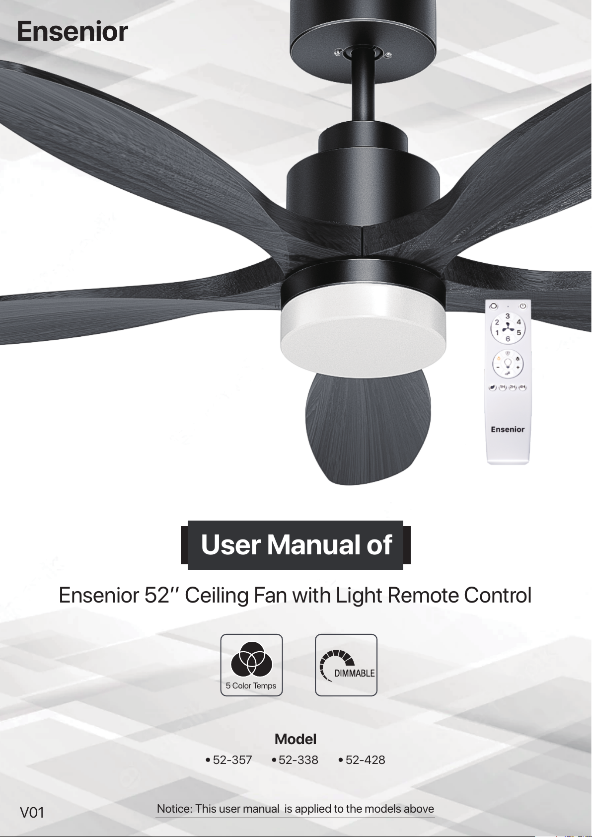
3. Wiring
Slide the downrod through the opening in hanger bracket. Align the hanging ball slot with the hanger bracket tab, installing the ball end of the
downrod into the opening of hanger bracket. Make sure the top of the hanging ball is in a horizontal position.
In angled mount situation, make sure the opening of the hanger bracket is right up towards the ceiling (see figure 2.6).
If your ceiling fan is standard mount, just skip this step.
Warning: Failure to align the hanging ball slot with the hanger bracket tab may cause the fan to fall, which could result in injury or death.
Figure 2.6
Plug the A1 connector of the receiver to the
A2 connector from the motor. Plug the B1
connector of the receiver to the B2 connector
from the motor. Please make sure all the
connections are secured.
A1 & A2 for the light, B1 & B2 for the fan.
Take off the wire skins (already cut) of the yellow wire of the downrod.
On the other side of the receiver, there is one black wire and one white wire.
On the one side of the hanger bracket, there is a place for connecting the receiver with
the household power supply from the outlet box (figure 3.2). Loosen all the 6 screws in
there with a flat head screwdriver.
Screw all of them tight with a flat head screwdriver.
Option 1
Option 2
3.1
3.2
Plug the yellow wire of the downrod into B
Figure 3.1
C
B
A
c
b
a
Plug the white wire of the receiver into A
Plug the black wire of the receiver into C
Plug the neutral supply wire into a
Plug the ground/earth supply wire into b
Plug the live supply wire into c
Plug the yellow wire of the downrod into b
Plug the white wire of the receiver into a
Plug the black wire of the receiver into c
Plug the neutral supply wire into A
Plug the ground/earth supply wire into B
Plug the live supply wire into C
Figure 3.2
B1
A1
A2
B2
Figure 2.5
x
8
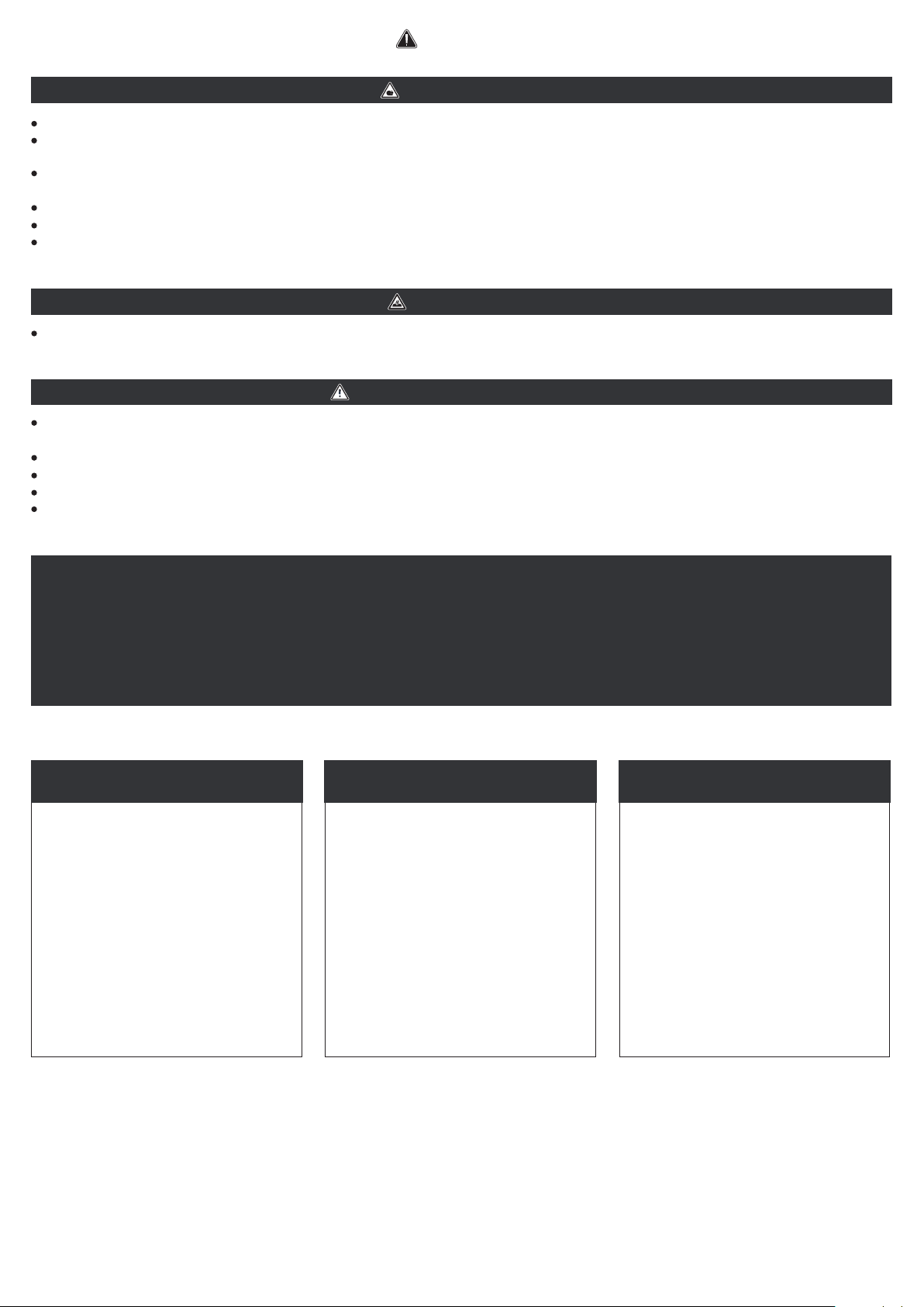
4. Attaching the Fan Blades
Put the receiver on the top of the hanging ball in the hanger
bracket. Make sure all the connections are secured.
Loosen the two screws (Phillips round pan screws) on the hanger
bracket. Raise canopy to hanger bracket, aligning the loosened screws
with the keyhole slots in the canopy. Twist counterclockwise the canopy
to lock and secure the screws tight with a Phillips screwdriver.
3.3 3.4
4.1
5.1 5.2
Figure 3.3 Figure 3.4
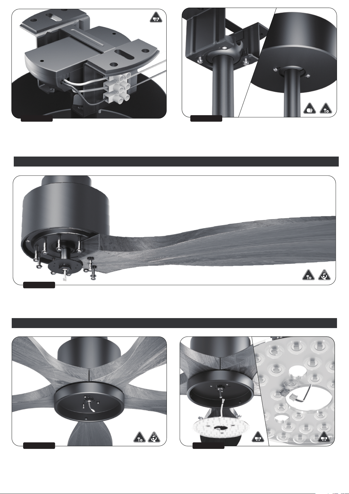
5.Assembling the Light Kit
Figure 4.1
Locate blade screws and washers in the hardware pack. Make sure the labeled side of the blade is upwards. Insert blade screws (along with
washers) into the hole of the blade with fingers first and then tighten the screws and washers a bit with a Phillips screwdriver (Do not screw them
tight first). One blade needs two blade screws and two washers. Repeat this step for the remaining blades. After finishing installing all the blades
in this way, secure all the screws tight.
Remove one of the screws at the bottom of the motor, and loosen the
other two. Thread the wire from the bottom of the motor through the
center hole of the fitter plate for light. Align the keyhole slots of the
fitter plate with the two loosened screws. Twist counterclockwise the
fitter plate to lock and screw the two screws tight. Reinstall the other
screw that was previously removed and screw it tight.
Plug the connector from the motor bottom into the LED light source.
Directly attach the LED light source to the fitter plate as they have
magnets for each other (make sure their centers are aligned).
Choose one of the situations in Figure 5.2 that is the actual situation
for you.
Figure 5.2Figure 5.1

9
6.Remote Control Instructions
Lift the shade and align the notches in the shade with tabs in the fitter
plate. Attach the shade to the fitter plate by twisting it clockwise until it is
installed into place and cannot be twisted anymore.
Warning: Make sure the shade is installed securely, otherwise it may fall
and cause injury.
5.3
6.1 6.2
6.3
Remove the battery cover from the back of the remote and insert two
AAA batteries (not included in the package), making sure positive (+) to
positive (+) and negative (-) to negative (-). Reinstall the battery cover. If
the batteries are installed correctly, the LED indicator at the top of the
remote should illuminate red light when any button is pressed.
If desired, the wall bracket in the remote pack can be installed into a wall
using the provided screws for wall bracket and wall anchors in the remote
pack. The remote can be stored in the mounting bracket for easy access.
Figure 5.3
Figure 6.1
Battery CoverBattery
5.4 Finish assembling the fixture.
Figure 5.4
Figure 6.2
Screw
Wall Bracket
Wall Anchor
Make sure everything is installed correctly and securely. Turn
on the power supply that was previously turned off. The remote
is already paired for use.
Figure 6.3

10
6.4 If the light at the top of the remote blinks red when you press any button, that is an effective press.
Turn On/Off the Fan
Reverse the Fan's Direction 0201
03
05
08
10
12
11
13
09
06
07
04
Turn Off the Whole Fixture
Sleeping Mode
Security Mode
Color Temperature - Color Temperature +
Change Speeds
Natural Wind Mode
Brightness +
Timer
Brightness - Turn On/Off the Light
Figure 6.4
Reverse the Fan's Direction
Press to change the direction of the running fan.
Downdraft: making you feel cooler in warm or hot weather
Updraft: making you feel warmer in cool or cold weather
Notice: After pressing the button, wait no more than 10 seconds for the fan to reverse its direction.
Turn Off the Whole Fixture Turn off both the fan and the light.
Notice: It CANNOT TURN ON both the fan and the light.
Turn On/Off the Fan Turn on/off the fan.
Change Speeds Different speeds of the running fan. Speeds range from low (1) to high (6).
Turn On/Off the Light Turn on/off the light.
Security Mode
One minute after pressing the button, the light turns off and the fan stays the same.
Press again to cancel.
Color Temperatures +
The higher the color temperature is, the whiter the lighting is.
Press: adjust the color temperature level by level
Press and hold: adjust the color temperature successively
Color Temperature -
The lower the color temperature is, the warmer the lighting is.
Press: adjust the color temperature level by level
Press and hold: adjust the color temperature successively
Brightness -
Make the lighting brighter.
Press: adjust the brightness level by level
Press and hold: adjust the brightness successively
Brightness +
Make the lighting dimmer.
Press: adjust the brightness level by level
Press and hold: adjust the brightness successively
Sleeping Mode
Simulates occupancy while you are away from home. Press the button and the light is set to the
brightest and the fan stops, and 10mins later the light turns off. And then the light will randomly
turn on for 10mins at random intervals. Light will blink once to confirm the security mode is
activated.
Press any buttons except for Timer buttons and Security Mode button to cancel.
Natural Wind Mode Simulate the effect of natural wind.
Press any of the 6 buttons of fan speed to cancel.
Timer
Press 1H/2H/4H button, and 1 hour/2 hours/4 hours later, the whole fixture will stop. (Make sure
the fan and light settings are what you want before pressing any timer buttons).
Press any other buttons (except for the 3 timer buttons) to cancel.
01
02
03
04
05
07
08
09
10
11
12
13
06

11
Problem and Solution
If the problem still cannot be solved after troubleshooting, please contact Ensenior customer service: service@ensenior.net
We have received feedback from more than 1000 customers every year. According to our statistics, 95% of customers' problems are related to the
method of installation, which could be solved by customers themselves. To save your valuable time, please read the troubleshooting first to quickly
identify the cause if you encounter any problems.
A "new fan" smell is rare but can happen. The smell is in no way harmful. Please run your fan on high speed
for 24 consecutive hours, and the smell will disappear. If you have any further questions, please do not
hesitate to contact us.
Remember: Always contact a certified electrician to do any necessary repairs, especially when wiring is involved! Make sure everything
is installed correctly and securely every time.
The fan has an odor
Press the remote’s “turn on/off the fan” buttons to ensure it is on.
Check the household power supply to ensure the power is turned on.
Make sure no one else has ever pressed the timer buttons, or accidentally pressed the security mode button.
Turn off the power supply, 1) Make sure the blades spin freely by hand; 2) Loosen the canopy and check all
the connections.
The fan does not
work/stops working
First of all, turn off the power.
Ensure the mounting bracket is secured to the building support structure and that the screws are tight.
Check to see if any of the blades are cracked.
Check to see if the fitter plate for light is securely installed.
Clicking noises in a fan are most often caused by loose blades. Check all the screws and screw them tight.
The fixture is
making a noise
Special noises
If you can tell the fan is getting power because the motor is charged and the lights turn on, but the blades
won’t spin, it could be caused by a wiring issue.
The blades are not
spinning
Turn off the fan and the power first.
Check all the blade screws. Make sure they are screwed tight and correctly.
Support the fan carefully and check that the hanging ball of the downrod is properly seated.
Loosen and lower the canopy cover to examine the hanger bracket and make sure the fan is mounted properly. If the
bracket is loose, use a screwdriver to tighten it. The bracket must be flush without movement against the building
support structure.
Lift up the yoke cover and tighten the set screws on the yoke until secure.
Look for warped blades. If even one blade is slightly distorted, it can create an imbalance. Check for warping by
standing on a secure ladder and looking down the edge of the blade toward the motor. If there’s any curvature, the
blade is considered warped.
Switch one blade with a blade from the opposite side.
Balance the fan by using the blade balancing kit to even out the blade weight distribution. If you are not sure about
how to use the balancing kit correctly, please see the instructions shown at the end of this troubleshooting page.
The fan wobbles
excessively when
running
Make sure no one else has ever pressed the sleeping mode button.
Turn off the power first, 1) Ensure the LED light source is securely connected to the motor; 2) Ensure the
connector for the light from the motor is securely connected to the receiver; 3) Check all connections at the
ceiling outlet box.
The fan operates
correctly but the
lights are not working
Turn off the power first, 1) Ensure the LED light source is securely connected to the motor; 2) Ensure the
connector for the light from the motor is securely connected to the receiver.
Make sure the batteries are installed correctly.
Insert new AAA batteries in the battery compartment of the remote to make sure the remote is powered.
If there are several fans in close proximity, turn power off to other fans and try the remote again.
Turn off the power and check the connections of the receiver.
The light is flickering
The remote control
does not work
Clicking
If you notice crackling or sizzling around the fixture, you should turn off power to the fan immediately. If an
odor like a popcorn-type smell is coming from the fixture or you hear a crackling noise, you will likely need
to contact customer service to troubleshoot the source of the issue.
Crackling or sizzling
Check that the LED light source receives the correct wattage.
Check the receiver: a defective receiver can create a humming noise.
If you've tracked the buzzing to an outlet or wiring, arrange for a certified, professional electrician to
repair it.
An electrical hum can come out of a circuit breaker if it is overloaded with current and not shutting off as
it's meant to. Please contact a certified, professional electrician to investigate and repair the cause of the
buzzing.
A defective motor can potentially cause buzzing.
Electrical buzzing or humming
TROUBLESHOOTING
07

12
How to use the balancing kit
1. Make sure your fan is properly installed and all fasteners are secure.
Running the fan at the highest speed is ideal for performing the
following steps and confirming their testing results.
2. With your fan stopped, attach one clip to the edge of any blade. Run
your fan and observe the wobble. Stop the fan and move the clip to the
next blade. Repeat this process on all of the fan blades until you found
the wobble is the least.
Notice: if there are two balancing clips in the pack, the other one is
used as a spare.
3. Move the clip to the edge of the blade that caused the least wobble
identified in the last step. Run your fan and observe the wobble. Adjust the
clip in small increments along the edge of the blade until the least wobble
is achieved.
Notice: the clip should be attached to places of uniform thickness (shown
as the picture above)
4. At the location where you noticed the least wobble, firmly
adhere the balance weight to the blade in line with the clip and
remove the clip.
12HOURS
Quick Response 12HOURS
QUCIK RESPONSE
If there is any problem with our light, please
refer to the Troubleshooting page on the back.
If you still could not fix this, please contact us
immediately. It doesn't matter if you have
installed the product, we will respond within
12 hours.
The fastest way to help us confirm the problem
is to send us a video of the problematic light to
our official email box.
30 DAY S
Money Back 30-DAY
MONEY-BACK
For 30 days after the date of purchase,
return your Ensenior product and receive a
full refund for ANY reason.
FRIENDLY REMINDER
We sincerely hope to solve the problem
for you.
We do NOT recommend that you leave a
product rating first, because we cannot
obtain your contact information through
the review/feedback, nor can we obtain
your relevant information and provide
you with compensation.
X
AFTERSALES SERVICE
08
13
Contact Us
Please rest assured that our service aim is to make customers 100% satisfied. If there is any problem, please contact us as soon as possible,
we will not let you down.
1. The LED Light Source: Three-Year Limited Warranty
If your LED Light Source (not including the fitter plate and the shade) fail at any time within three years of the date of purchase due to a defect in
material or workmanship, as determined solely by Ensenior, Ensenior will provide the replacement free of charge.
2. Motor: Limited Lifetime Warranty
If any part of your ceiling fan motor fails during your ownership of the fan due to a defect in material or workmanship, as determined solely by
Ensenior, Ensenior will provide you with the replacement free of charge. The foregoing limited warranty applies only to the motor itself and does
not apply to electronic controls – such as the remote, or the receiver. Such electronic control items are INCLUDED IN THE ONE-YEAR LIMITED
WARRANTY BELOW.
3. Other: One-Year Limited Warranty
Except as otherwise indicated throughout this warranty, if any part of your Ensenior ceiling fan fails at any time within one year of the date of
purchase due to a defect in material or workmanship, as determined solely by Ensenior, Ensenior will provide the replacement free of charge.
The Warranty Does NOT Cover:
There is no warranty for
Remote control batteries;
Fans owned by someone other than the original purchaser;
Fans for which proof of purchase has not been established;
Fans purchased from an unauthorized dealer;
Ordinary wear and tear;
Minor cosmetic blemishes;
Refurbished fans;
Fans that are damaged due to any of the following: improper installation, misuse, abuse, improper care, failure to follow Ensenior instructions,
accidental damage caused by the fan owner or related parties, modifications to the fan, improper or incorrectly performed maintenance or
repair, improper voltage supply or power surge, use of improper parts or accessories, failure to provide maintenance to the fan, or acts of God
(e.g. flood).
ORIGINAL PURCHASER’S SOLE AND EXCLUSIVE REMEDY FOR A CLAIM OF ANY KIND WITH RESPECT TO THIS PRODUCT SHALL BE THE
REMEDIES SET FORTH HEREIN. ENSENIOR IS NOT RESPONSIBLE FOR CONSEQUENTIAL OR INCIDENTAL DAMAGES, DUE TO PRODUCT
FAILURE, WHETHER ARISING OUT OF BREACH OF WARRANTY, BREACH OF CONTRACT, OR OTHERWISE. Some States do not allow the
exclusion or limitation of incidental or consequential damages, so the above limitation or exclusion may not apply to you.
ANY IMPLIED WARRANTIES OF MERCHANTABILITY OR FITNESS FOR A PARTICULAR PURPOSE APPLICABLE TO THIS PRODUCT ARE
LIMITED IN DURATION TO THE PERIOD OF COVERAGE OF THE APPLICABLE LIMITED WARRANTIES SET FORTH ABOVE. Some States do not
allow limitations on how long an implied warranty lasts, so the above limitation may not apply to you.
How Does State Law Affect Warranty Coverage?
This warranty gives you specific legal rights. You may also have other rights which vary from state to state.
WARRANTY WARRANTY
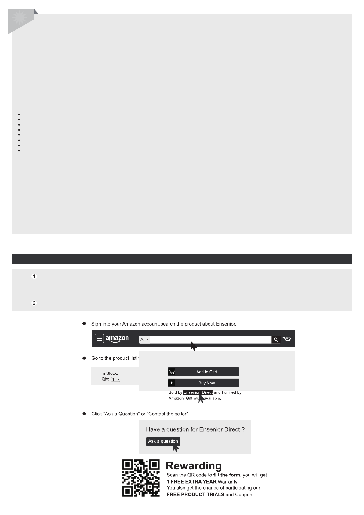
Contact by “Ask a quesion” on the “Ensenior” Seller Page.(7x24H)
Because Amazon’s information system sometimes can’t successfully receive and send information, in which case you may not
receive our response. We will never be able to reply to your inquiry. If you find that we have not responded to you within 24
hours, please send us an e-mail.
Contact via Email: service@ensenior.net(7x24H)
Ensenior ceiling fan with light remote control

Perfect Lighting Solution to Enhance Your Life
Ensenior
This manual suits for next models
2
Table of contents
Popular Fan manuals by other brands


Makita
Makita DCF201Z instruction manual

Chiller
Chiller Giant 700 Installation, operation and maintenance manual

Hurricane
Hurricane W Instruction guide

Delta Electronics
Delta Electronics AFB04512HB Dimensions and installation information

Bionaire
Bionaire BWF0910AR Instruction leaflet

Miller
Miller Hydracool 1 owner's manual

Selkirk
Selkirk Polyflue BH Installation and maintenance instructions

Vivax
Vivax FS-40WTB user manual

Monte Carlo Fan Company
Monte Carlo Fan Company 5KC48 owner's manual

Helios
Helios MultiVent MV EC Series Installation and operating instructions

CristalRecord
CristalRecord Slice instruction manual

Vostermans
Vostermans VF9427B Assembly manual