Chiller Giant 700 User manual

GIANT
Vari
N02541445 Rev. A
EN
Installation, Operation, and
Maintenance Manual
GIANT
Vari
Chiller Oy will not assume responsibility for any errors or shortcomings that may appear in this document.
The end user is responsible for ensuring that the unit operates appropriately and safely. Working with
electric components is subject to permission. Always abide by the existing national legislation, regulations
and standards.
Chiller Oy is constantly developing its products and reserves the right to change its products.
GIANT Vari™ is a registered trademark of Chiller Oy.
All rights reserved © Chiller Oy 2020.
Chiller Oy
Address: Louhostie 2, FI-04300 Tuusula
Finland
Telephone: +358 9 274 7670
E-mail: info@chiller.fi
Internet: www.chiller.eu
Approvals and version history
REVISION DATE DESCRIPTION
OF CHANGE
APPROVED BY
A 04.12.2020 First issue MH
2 (40) Copyright © 2020. All rights reserved.
GIANT Vari – Installation, Operation, and Maintenance Manual N02541445 Rev. A

Contents
1 General ............................................................................................................4
1.1 About this manual.....................................................................................4
1.2 Guarantee................................................................................................4
1.3 Inspection of the unit.................................................................................4
1.4 Related documentation .............................................................................5
2 Safety...............................................................................................................6
2.1 General safety instructions ........................................................................6
2.2 Safety-related signs ..................................................................................6
2.3 Safety symbols.........................................................................................6
3 Unit overview ...................................................................................................8
3.1 Introduction of the unit...............................................................................8
3.2 Unit dimensions......................................................................................10
3.3 Type plate .............................................................................................. 11
3.4 Automation options and control connections .............................................12
3.5 Vari-option..............................................................................................12
4 Installation of the unit.....................................................................................14
4.1 General installation instructions ...............................................................14
4.2 Choosing the installation site ...................................................................15
4.3 Mounting the unit to the ceiling.................................................................16
4.4 Mounting the unit to the wall ....................................................................18
4.5 Attaching the water connections ..............................................................21
4.6 Installing sewerage for condensation water...............................................22
4.6.1 Sewerage without condensation water pump ...............................22
4.6.2 Sewerage with condensation water pump (option) .......................23
4.7 Attaching the electrical connections .........................................................27
4.8 Testing the condensation water pump.......................................................28
5 Operation of the unit ......................................................................................30
5.1 Controlling the unit..................................................................................30
6 Maintenance of the unit..................................................................................31
6.1 Maintenance schedule ............................................................................31
6.2 Opening the maintenance hatches ...........................................................31
6.3 Cleaning and replacing the filter ...............................................................33
6.4 Cleaning the condensation water basin ....................................................35
APPENDIX A: Vari-option control connections ...................................................37
EN
Copyright © 2020. All rights reserved. 3 (40)
N02541445 Rev. A GIANT Vari – Installation, Operation, and Maintenance Manual

1 General
1.1 About this manual
This Installation, Operation, and Maintenance Manual has been prepared as
general instructions for appropriate installation, operation, and maintenance
procedures. When operating the unit, always follow the precautionary
instructions related to each component as well as the regulations and
recommendations given by the local authorities.
The unit must be installed, operated, and maintained by a professional and in
such a way that it does not cause danger to humans, the environment, or the
unit itself. The unit must not be used for other than its intended purposes without
a written consent from the manufacturer.
NOTICE
Before you start to install, operate, or maintain the system, read this manual
carefully and familiarize yourself with all of the instructions.
Keep the manual for later reference.
1.2 Guarantee
The guarantee for this unit is based on Chiller Oy’s terms of guarantee.
The guarantee becomes void, if:
•the product is modified or repaired without a written consent from Chiller Oy
•the unit parameters are modified without permission
•the configuration of the unit is changed
•the installation site, unit connections, installation ground, or installation
procedures do not follow these instructions
•the instructions in this Installation, Operation, and Maintenance Manual are
not followed.
The guarantee does not cover damages, if:
•the user does not follow the manufacturer’s instructions
•the unit is used in a way that it is not designed for and that causes damage to
the unit
•the unit is not maintained according to the schedule and instructions in this
manual
Note! Warranty claims are processed only, if the complete type and serial numbers
of the unit (see Section 3.3 Type plate) are notified to the manufacturer in written
form.
1.3 Inspection of the unit
The units are shipped from the factory as assembled (apart from some
accessories), wired, and tested.
4 (40) Copyright © 2020. All rights reserved.
GIANT Vari – Installation, Operation, and Maintenance Manual N02541445 Rev. A

When you receive the unit:
1. Inspect the delivery against the order.
2. Verify that the contents of the delivery meet the order.
3. Inspect all the delivered units carefully.
a. If the units have transport damages, notify the expeditor and the seller of
them.
b. Record the transport damages on the bill of freight.
c. Send a complaint about the damages to the transport company within 24
hours of delivery.
1.4 Related documentation
In addition to this manual, the unit is delivered with a unit-specific wiring
diagram.
In case you need a new wiring diagram, you can order it. You need the unit
serial number from the type plate for the order (see Section 3.3 Type plate).
EN
Copyright © 2020. All rights reserved. 5 (40)
N02541445 Rev. A GIANT Vari – Installation, Operation, and Maintenance Manual
2 Safety
2.1 General safety instructions
This unit is designed so that it does not expose people to hazard or risk,
provided that:
•The unit is installed, operated, and maintained according to the instructions
in this manual.
•No structural changes are made to the unit.
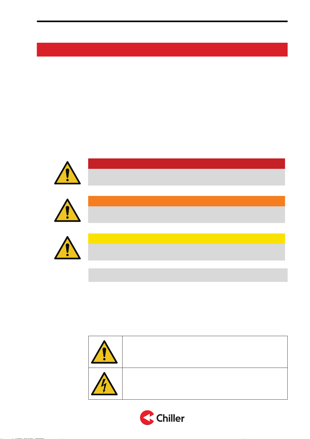
2.2 Safety-related signs
These are the safety-related signs used in this manual.
DANGER
DANGER indicates a hazard with a high level of risk which, if not avoided,
will result in death or serious injury.
WARNING
WARNING indicates a hazard with a medium level of risk which, if not
avoided, could result in death or serious injury.
CAUTION
CAUTION indicates a hazard with a low level of risk which, if not avoided,
could result in minor or moderate injury.
Note! Notes are used to indicate important information and useful tips.
2.3 Safety symbols
Hazard symbols
These symbols indicate a hazardous situation or action. Symbols are used to
warn of situations, which can cause environmental damage and personal injury.
General warning sign
Electrical hazard
6 (40) Copyright © 2020. All rights reserved.
GIANT Vari – Installation, Operation, and Maintenance Manual N02541445 Rev. A
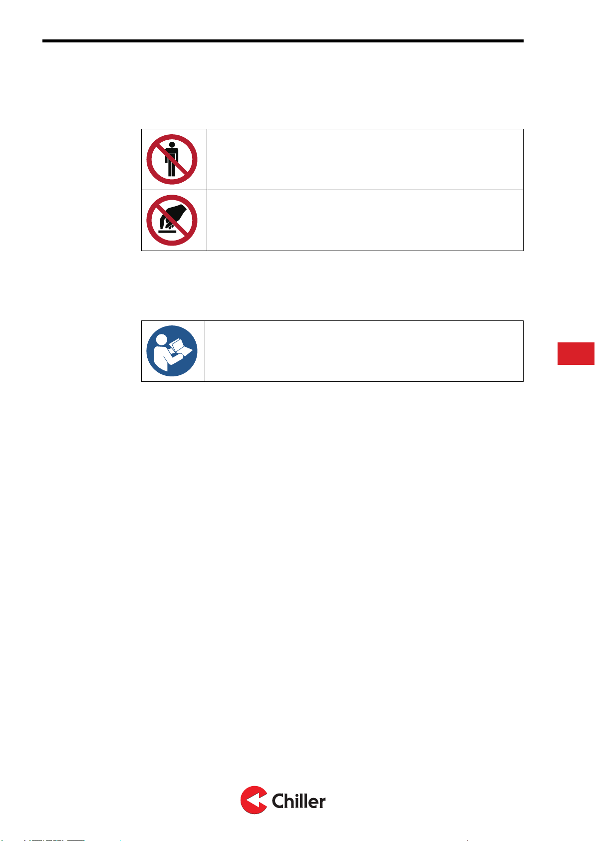
Prohibited action symbols
These symbols are used in warnings and notifications to indicate an action that
should not be taken. The prohibited action symbols are shown below.
Limited or restricted access
Do not touch
Mandatory action symbols
These symbols are used in warnings and notifications to indicate an action that
must be taken. The mandatory action symbols are shown below.
Read the manual or instructions
EN
Copyright © 2020. All rights reserved. 7 (40)
N02541445 Rev. A GIANT Vari – Installation, Operation, and Maintenance Manual
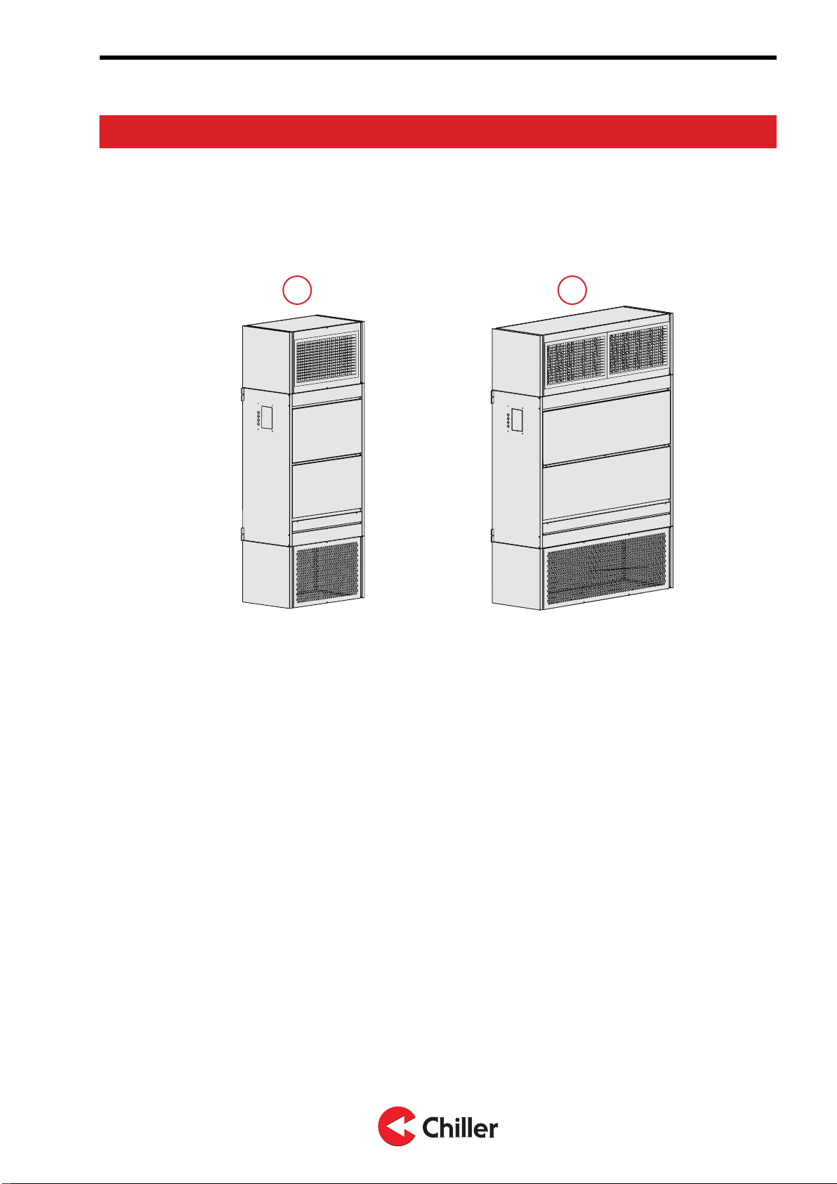
3 Unit overview
3.1 Introduction of the unit
The Giant fan coil unit is designed for room air conditioning. The unit is available
in two sizes, Giant 700 and Giant 1300.
21
Figure 1: Available unit sizes
1. Giant 700
2. Giant 1300
Figure 2: Overview of the unit shows an example of the Giant 700 unit assembly.
The unit is available in left- and right-handed configurations. This refers to the
side where the pipe connections are located, when you view the unit from the
direction of the maintenance hatches.
8 (40) Copyright © 2020. All rights reserved.
GIANT Vari – Installation, Operation, and Maintenance Manual N02541445 Rev. A
6
10
1
7
8
9
2
3
11
4
12
5
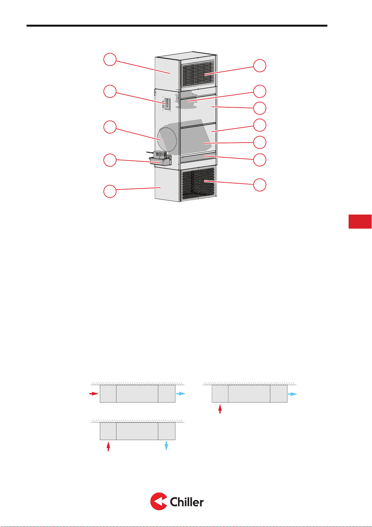
Figure 2: Overview of the unit
1. Exhaust chamber
2. Electrical box
3. Water connections
4. Condensation water pump or free drain outlet
5. Suction chamber
6. Pressure chamber grille
7. Fan
8. Maintenance hatch, fan
9. Maintenance hatch, coil
10. Coil
11. Maintenance hatch, filter
12. Suction chamber grille
The unit is delivered with one of the following configurations: horizontal, upward,
or downward air direction. The pressure and suction chambers are identical in
size, which allows the air supply directions to be freely selected and adjusted.
•If the unit supplies air horizontally, mount the unit to the ceiling. For more
information, see Section 4.3 Mounting the unit to the ceiling.
•If the unit supplies air upwards or downwards, mount the unit to the wall. For
more information, see Section 4.4 Mounting the unit to the wall.
Figure 3: Options for air supply directions (ceiling, digit HZ)
EN
Copyright © 2020. All rights reserved. 9 (40)
N02541445 Rev. A GIANT Vari – Installation, Operation, and Maintenance Manual
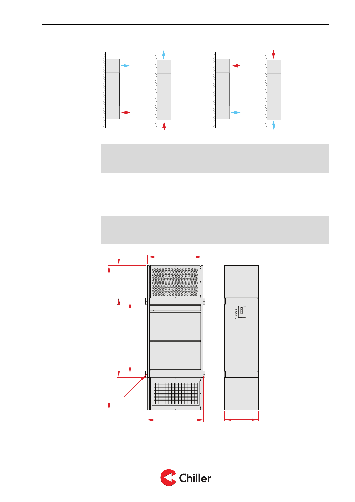
Figure 4: Options for air supply directions (wall, digit UP or DW)
Note! You can find the air supply direction for the unit on the type plate. The air
supply directions are marked digit HZ / digit UP / digit DW. For more information,
see Section 3.3 Type plate.
3.2 Unit dimensions
The unit comes in two sizes, Giant 700 and Giant 1300.
Note! The unit dimensions are given as reference. Chiller Oy reserves the right to
make changes to them. Check the actual dimensions from the order
documentation.
450
730
960
1050
753
R4,50
1900 425
Figure 5: Main dimensions of Giant 700
10 (40) Copyright © 2020. All rights reserved.
GIANT Vari – Installation, Operation, and Maintenance Manual N02541445 Rev. A

450
1330
960
1050
1353
1900 425
R4,50
Figure 6: Main dimensions of Giant 1300
3.3 Type plate
Type plate is located next to the electrical box.
Note! Record the type plate information on the unit card and file it carefully. The
type and serial numbers of the unit are required for identifying the unit when, for
instance, purchasing spare parts.
When you order maintenance or order spare parts, you always need the serial
number. You cannot make an order without the serial number.
The type plate specifies the following information about the unit:
TYPE Unit type Including accessories
(18 characters consisting of
letters and numbers)
SER.NR. Unit serial number Seven (7) number
combination
POWER Power type 230 VAC, 50 Hz
INPUT Electrical information Input power W and current
A, max. values*:
GIANT 700 / 460 W, 2 A
GIANT 1300 / 920 W, 4 A
MANUF.DATE Date of manufacture
*The actual input power of the unit is usually below the max. value. For
specific information, please contact your nearest reseller.
EN
Copyright © 2020. All rights reserved. 11 (40)
N02541445 Rev. A GIANT Vari – Installation, Operation, and Maintenance Manual

Figure 7: Example of the type plate
3.4 Automation options and control
connections
The unit is available with the automation option Vari. Once the unit is delivered,
you can see the automation type on the type plate (“Type”, unit type is Vari). The
automation option of the unit affects the way the fan coil is controlled and what
external equipment can be connected to the unit.
Note! Perform all electrical connections always according to the wiring diagrams
supplied with the unit delivery.
Note! When connecting the alarm signal to the BMS, add a 30 s filter time to alarm
management.
3.5 Vari-option
The automation option Vari has the following properties:
•Analogue control (0-10 V and 24 V AC/DC for on/off on all inputs)
•Suitable for analogue control from building automation or traditional room
controller
•Potential free alarm contact, open in alarm or when unit not powered
•No additional sensor inputs or control outputs.
See Appendix for further details.
12 (40) Copyright © 2020. All rights reserved.
GIANT Vari – Installation, Operation, and Maintenance Manual N02541445 Rev. A
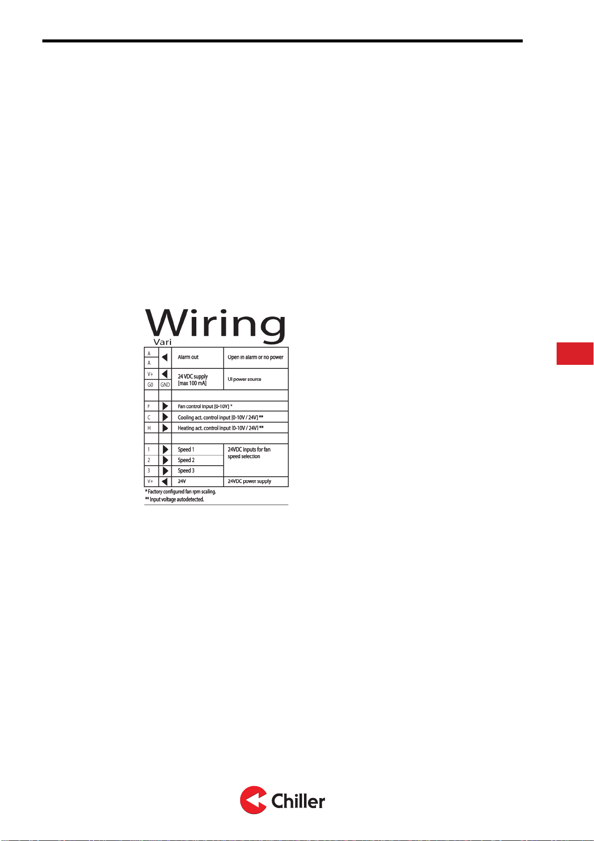
Figure 8: Vari control card
Figure 9: Vari wiring instructions on the electrical box cover
EN
Copyright © 2020. All rights reserved. 13 (40)
N02541445 Rev. A GIANT Vari – Installation, Operation, and Maintenance Manual
4 Installation of the unit
4.1 General installation instructions
CAUTION
Only professionally skilled and qualified personnel can install the unit.
Note! Always follow local safety regulations when you install, operate, and maintain
the unit. Read these instructions carefully before installing the unit.
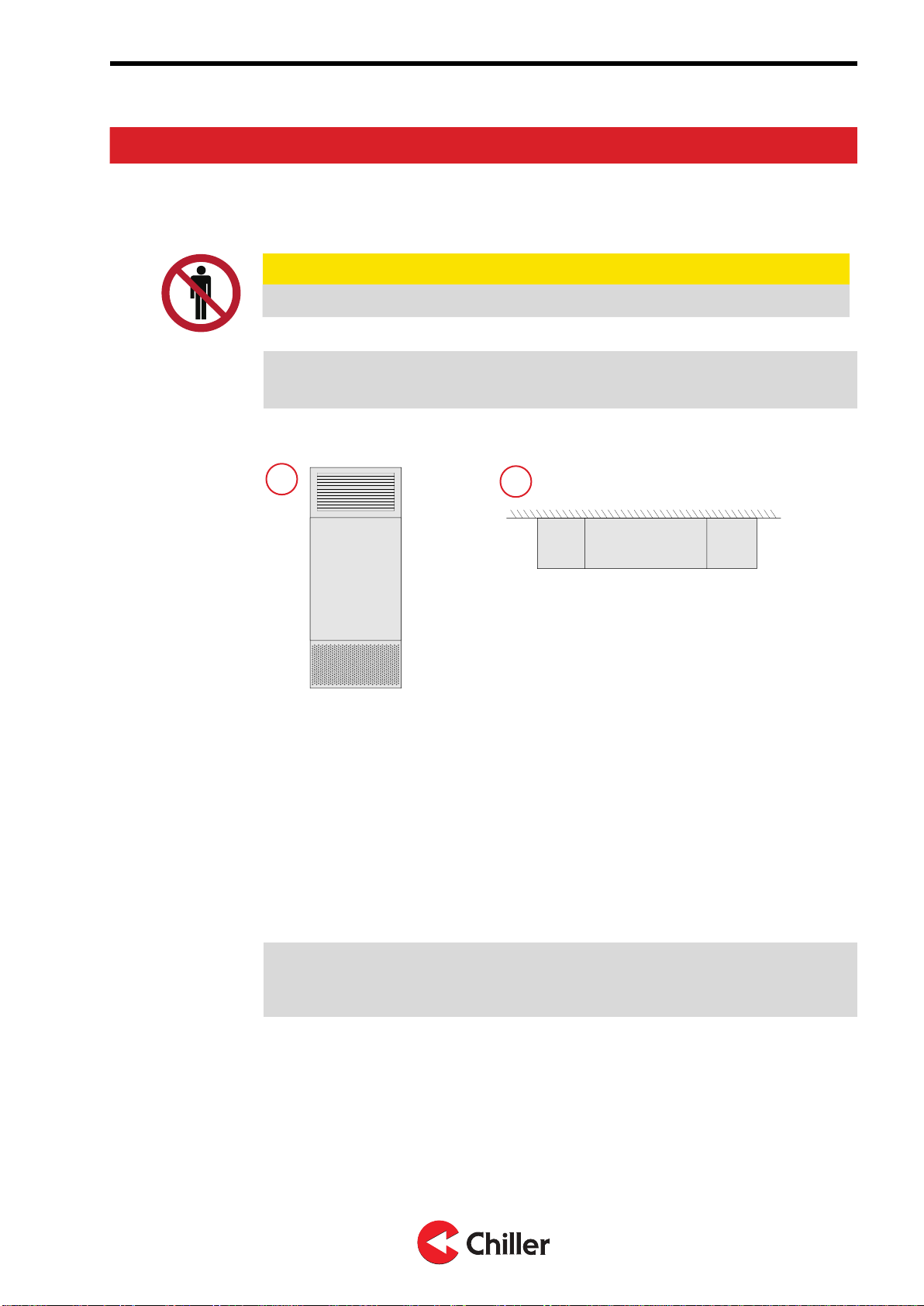
You can install the unit to the wall or to the ceiling, depending on the unit type.
12
Figure 10: Installation options
1. Wall installation (unit digit UP / DW)
2. Ceiling installation (unit digit HZ)
When you install the unit, make sure that
•the unit is mounted to the ceiling or wall firmly and that it does not cause
danger or harm to any person, object, structure, or equipment.
•all instructions given by the manufacturer and seller are followed.
•installation, lifting, and moving the unit is performed carefully.
•fire safety and the availability of fire equipment is ensured when performing
welding or soldering operations.
Note! The manufacturer is not accountable for installations that have not been
performed according to the installation instructions, or for using the unit in
conditions that differ from those specified in Section 4.2 Choosing the installation site.
The installation concept "Install, Use, Maintain" is applied with this unit.
The installation order of this concept is:
•installation on the ceiling or wall
•pipe connections
•electrical connections
•testing and commissioning of the unit.
14 (40) Copyright © 2020. All rights reserved.
GIANT Vari – Installation, Operation, and Maintenance Manual N02541445 Rev. A
Note! Do not remove any of the coverings that protect the unit openings before the
installation is complete and all dust has been cleared.
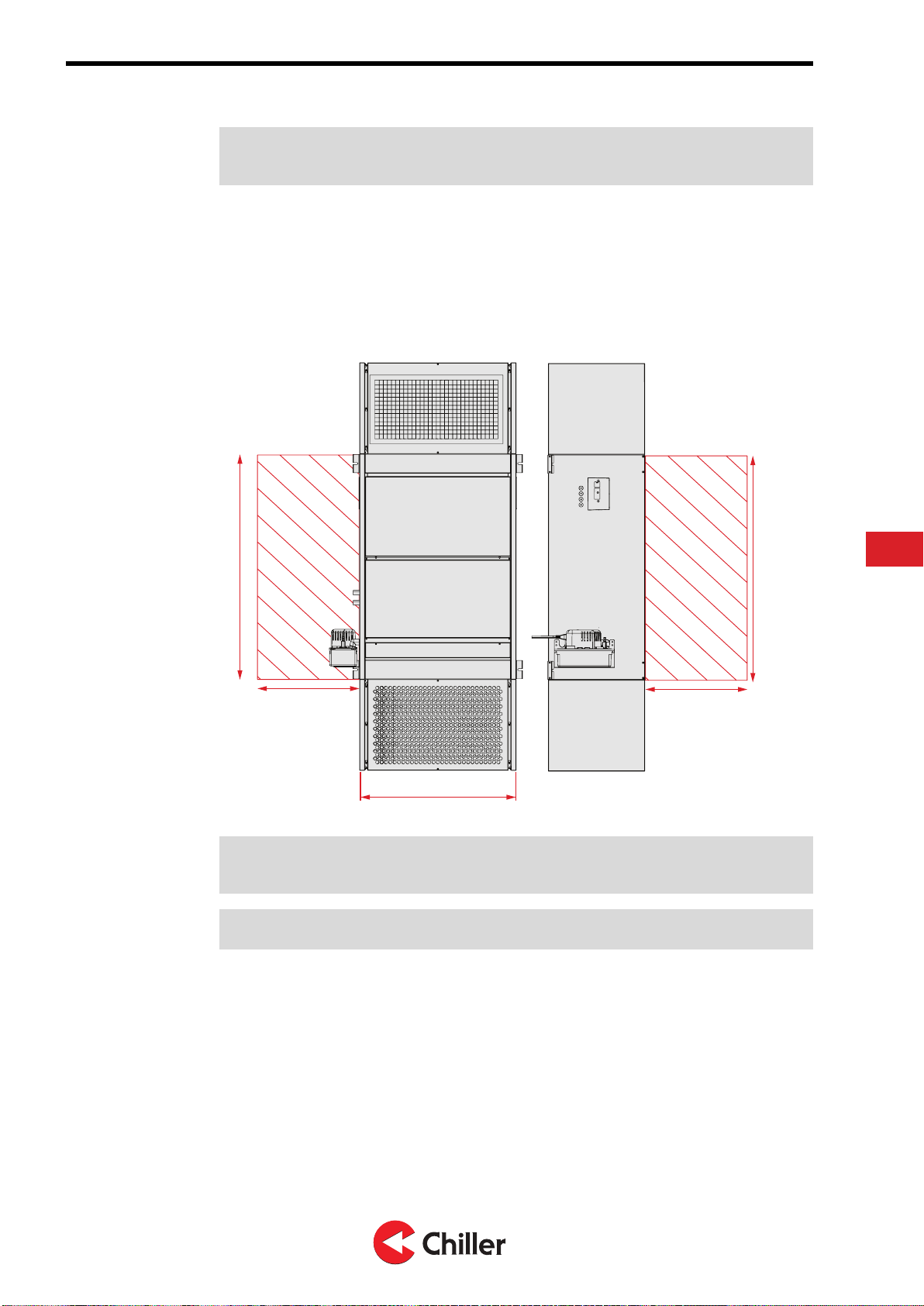
4.2 Choosing the installation site
When you choose the installation site for the unit, make sure that you leave
enough space around the unit for maintenance work. You can see the
dimensional requirements for the service area in Figure 11: Service area
requirements.
L
500
1020
500
1020
Figure 11: Service area requirements
Note! Always take local safety regulations and installation requirements into
account when choosing the installation site and before starting the installation.
Note! The dimension marked L varies depending on the unit type.
Take also the following matters into consideration, when choosing the
installation site:
•the requirements for the service room and the safety requirements for the
unit and its accessories must be complied with.
•the installed unit must be mounted in a level position.
•the unit must not be installed above any other units or equipment.
•the unit must not be installed in a room that has flammable or explosive
substances or has airborne substances that corrode PVC plastics, EPS
plastics, ABS plastics, copper, or aluminium.
•the unit must be installed in the room so that it allows free air circulation in
the unit.
EN
Copyright © 2020. All rights reserved. 15 (40)
N02541445 Rev. A GIANT Vari – Installation, Operation, and Maintenance Manual

•the unit must not be installed in a room where recirculation air can bring such
substances to the inlet opening of the unit that block air circulation (for
instance greases from the kitchen).
•the installation and maintenance room required for electrical installations,
pipe-laying, and installation of sewerage for condensation water.
Table 1: Limitations for the GIANT installation site
Temperatures Min. Max.
Indoor air 5 °C (A) 32 °C
Water 4 °C (B) 80 °C (C)
Ethyl alcohol (35%) 4 °C 80 °C
Ethylene glycol (35%) 4 °C 80 °C
Propylene glycol (35%) 4 °C 80 °C
Notes.
AIf the room temperature is below 0 °C, the unit must be drained of water and the
condensation water must be removed.
BFor lower temperatures, using anti-freeze agent is imperative.
CThe maximum water pressure is 1000 kPa/10 bar.
You can find the main dimensions of the unit in Section 3.2 Unit dimensions.
4.3 Mounting the unit to the ceiling
The unit is mounted to the ceiling from four (4) mounting points. The mounting points
are integrated in the unit frame. Use M8 fasteners, when you mount the unit to the
ceiling.
DANGER
Risk of severe injury. Make sure you attach the unit firmly to the ceiling. If the
unit is not properly attached, it can fall and cause severe injury.
1. Install the unit to the ceiling from the four (4) mounting points.
16 (40) Copyright © 2020. All rights reserved.
GIANT Vari – Installation, Operation, and Maintenance Manual N02541445 Rev. A
2. Use supports to mount the unit to the ceiling. Make sure that you use
supports that are suitable for the installation site and the ceiling material.
Note! The supports must be strong enough for the max. weight (GIANT 700 = 115
kg / GIANT 1300 = 185 kg) of the unit.
Note! Do not hoist the unit from pipe joints, valves, or the condensation water basin.
You can hoist the unit to the ceiling by using a lift, or similar.
WARNING
Use a hoist that is rated to handle the weight of the unit.
a. If you use threaded bars for supporting the unit, you must secure the joint
between the threaded bar and the support with locknuts and washers.
b. Make sure that the bars are attached tightly to the ceiling and they do not
come off.
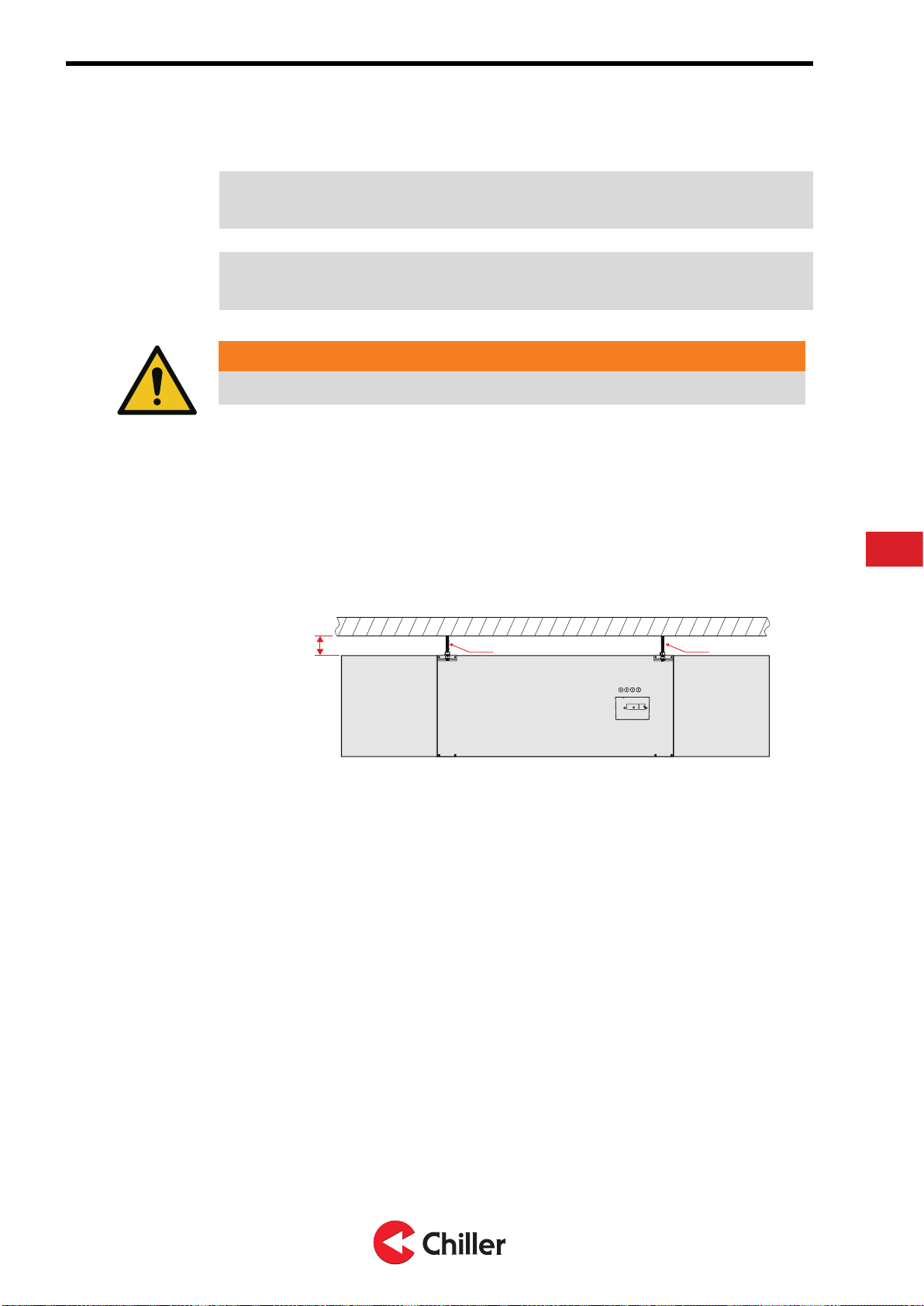
3. Make sure that the distance between the unit and the ceiling is at least 30
mm.
≥ 30 mm M8 M8
EN
Copyright © 2020. All rights reserved. 17 (40)
N02541445 Rev. A GIANT Vari – Installation, Operation, and Maintenance Manual
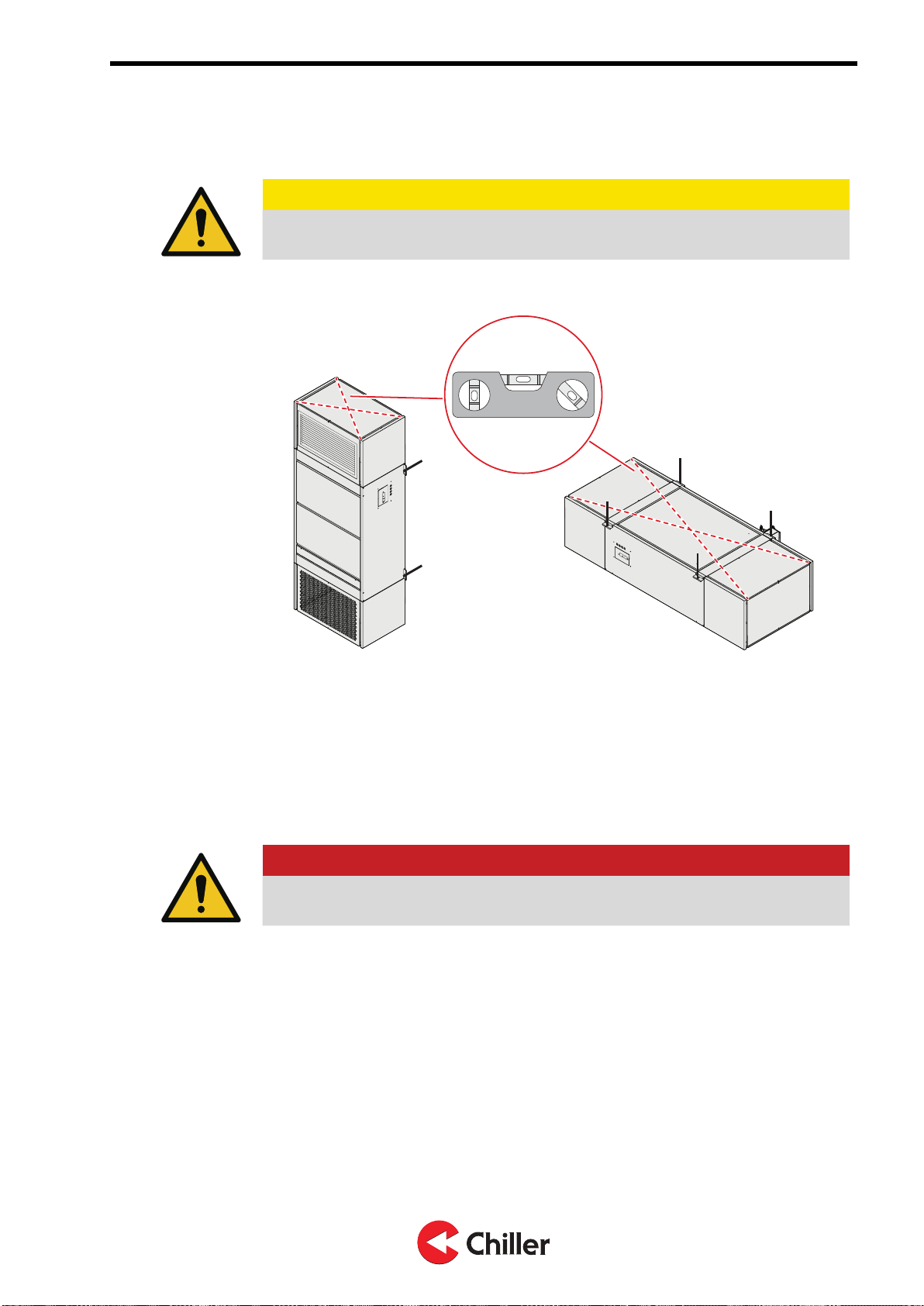
4. After you have mounted the unit to the ceiling, use a spirit level to make sure
that the unit is horizontally leveled.
CAUTION
The unit must be leveled. If the unit is not leveled properly, the condensation
water will run in a wrong way and this can damage the unit or surroundings.
5. Install the accessories (control valves, shut-off valves, external drain pan
etc.), if they are delivered as separate items.
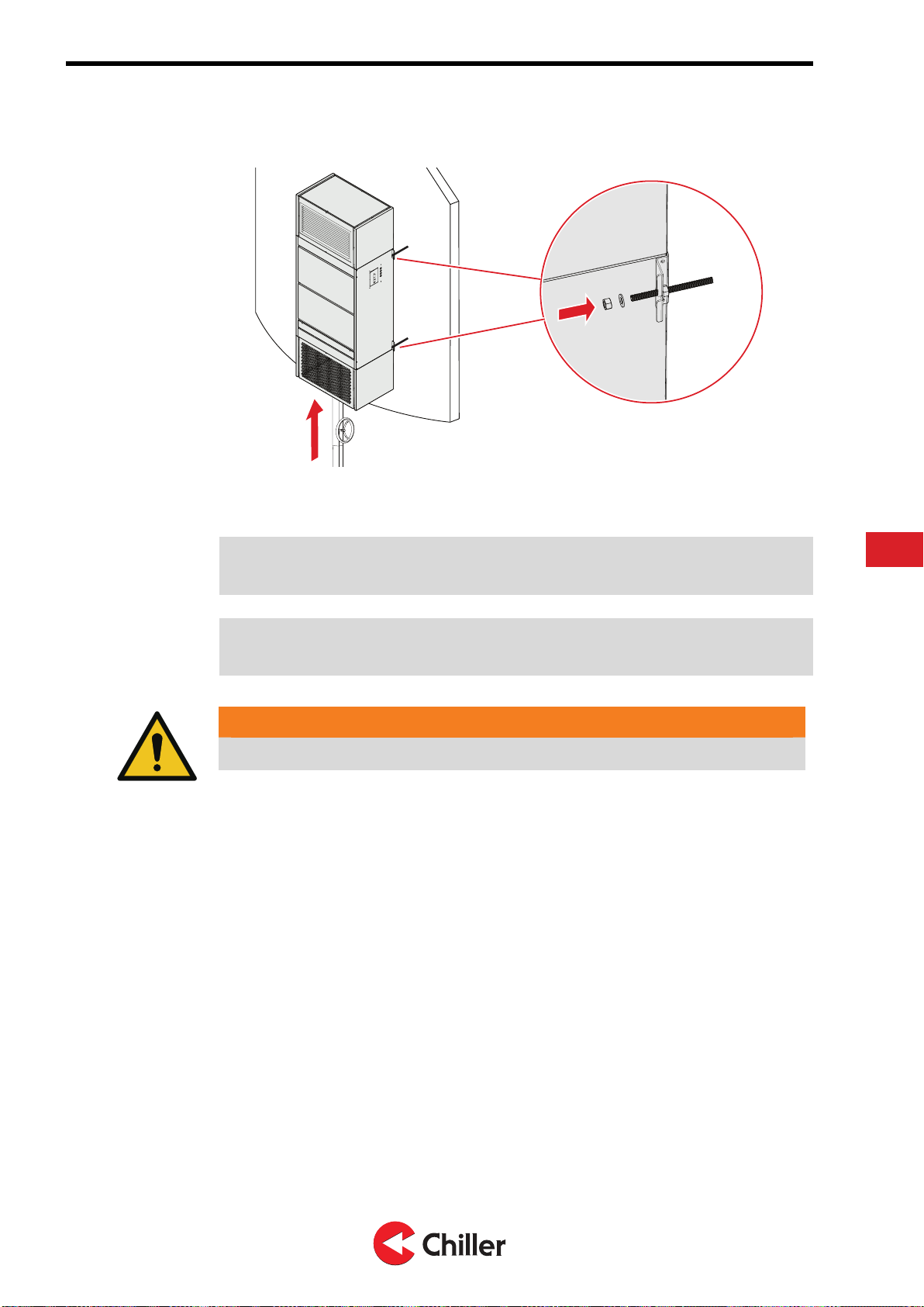
4.4 Mounting the unit to the wall
The unit is mounted to the wall from four (4) mounting points. The mounting points are
integrated in the unit frame. Use M8 fasteners, when you mount the unit to the wall.
DANGER
Risk of severe injury. Make sure you attach the unit firmly to the wall. If the
unit is not properly attached, it can fall and cause severe injury.
18 (40) Copyright © 2020. All rights reserved.
GIANT Vari – Installation, Operation, and Maintenance Manual N02541445 Rev. A
1. Install the unit to the wall from the four (4) mounting points.
2. Use supports to mount the unit to the wall. Make sure that you use supports
that are suitable for the installation site and the ceiling material.
Note! The supports must be strong enough for the max. weight (GIANT 700 = 115
kg/ GIANT 1300 = 185 kg) of the unit.
Note! Do not hoist the unit from pipe joints, valves, or the condensation water basin.
You can hoist the unit to the wall by using a lift, or similar.
WARNING
Use a hoist that is rated to handle the weight of the unit.
a. If you use threaded bars for supporting the unit, you must secure the joint
between the threaded bar and the support with locknuts and washers.
b. Make sure that the bars are attached tightly to the wall and they do not
come off.
EN
Copyright © 2020. All rights reserved. 19 (40)
N02541445 Rev. A GIANT Vari – Installation, Operation, and Maintenance Manual
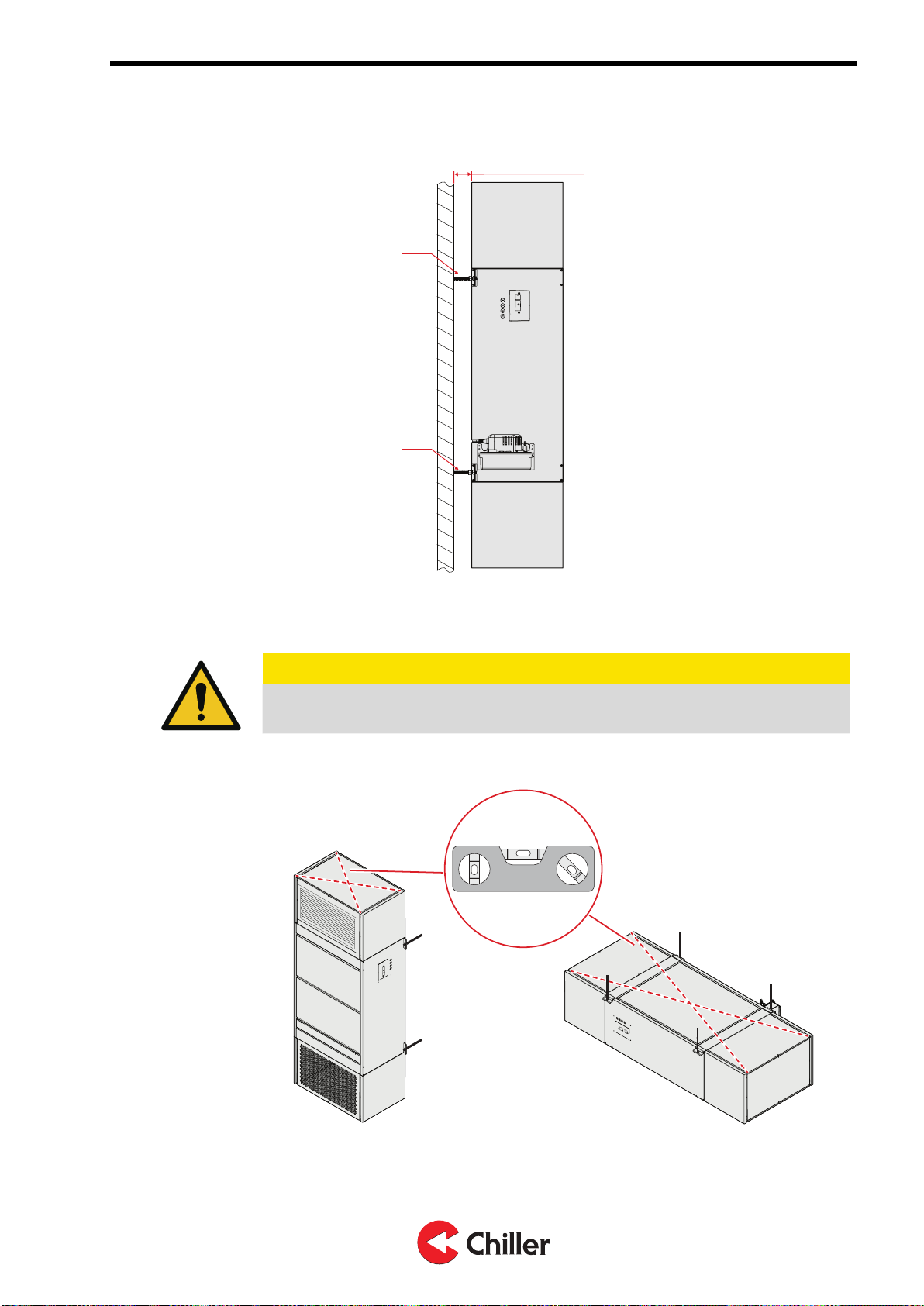
3. Make sure that the distance between the unit and the wall is at least 30 mm.
≥ 30 mm
M8
M8
4. After you have mounted the unit to the wall, use a spirit level to make sure
that the unit is horizontally leveled.
CAUTION
The unit must be leveled. If the unit is not leveled properly, the condensation
water will run in a wrong way and this can damage the unit or surroundings.
5. Install the accessories (control valves, shut-off valves, external drain pan
etc.), if they are delivered as separate items.
20 (40) Copyright © 2020. All rights reserved.
GIANT Vari – Installation, Operation, and Maintenance Manual N02541445 Rev. A
This manual suits for next models
1
Table of contents
Other Chiller Fan manuals

Popular Fan manuals by other brands


Craftmade
Craftmade Champion CHP60 installation guide

Helios
Helios MultiVent MV EC Series Installation and operating instructions

Hunter
Hunter Louden 51047 Owner's guide and installation manual

Bastilipo
Bastilipo Cala Salada instruction manual

Airflow
Airflow AV100T manual

Manrose
Manrose LED Series overview


