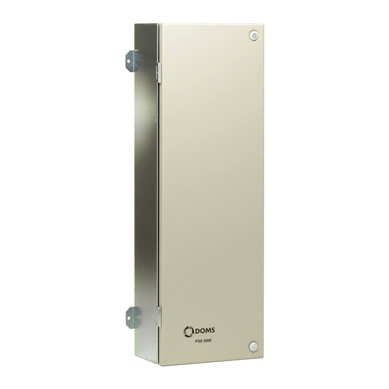
ENSIM SENSORS SK-R User manual

OPERATING
MANUEL
LEVEL CONTROL DEVICE
SK-R
Model :
Model: 42-2022-002
Information in this manual is reviewed and completely reliable. Responsibility is not assumed due to any typing error.
Products in this manual are available only for information purpose and they may be changed without notice.
1
Models :
Table of Contents :
General Information...........................................................................................................................................................................2
Installation .........................................................................................................................................................................................3
Failure Detection..............................................................................................................................................................................8
Disassembly of Instrument ............................................................................................................................................................8
Service .............................................................................................................................................................................................8
Recalibration....................................................................................................................................................................................8
Repair................................................................................................................................................................................................8
Disposal ...........................................................................................................................................................................................8
Terms of Warranty ..........................................................................................................................................................................8
Terms of Return ................................................8
1.
2.
3.
4.
5.
6.
7.
8.
9.
10.
Important Notes:
Used Symbols :
: Caution : Note : Disposal
Please read this manual carefully before installation of the level control device. User is responsible for accidents and losses arising
from failure to comply with the warnings in this manual.
In the event that level control device is broken, take measures in order to prevent accidents and losses which can occur in its system.
There is not any fuse and circuit breaker on the instrument; they should have been added to the system by the user.
This manual should be stored in an easily accessible place for subsequent use.
The manufacturer's liability cannot exceed the purchase price of the device according to the law.
Do not make any modification on the instrument and do not try to repair it. Reparation should be made by authorized service staff.
Do not operate the system before making assembly in compliance with the assembly chart related to the instrument.
Products which do not contain label and serial number are considered to be excluded from the warranty scope.
The instrument's useful life, determined and announced by the ministry, is 10 years.
SK-Pi
SK-Ps
SK-R
( Conductivity Type Pump Control)
(Switch Type Pump Control)
(4 Independent Relays)

2
1. General Information :
1.1. Material Acceptance
Check that there is no damage on the packages during the transportation immediately after the material acceptance. If packages are
damaged, open the packages immediately and check whether products are affected or not, if there is any damage, send your
complaint report to the transporter company and its photocopy to the address of our company.
11.2. Information about Areas of Use
It provides automatic driving of equipments that control the liquids in the tank (such as pump, hydrophore and solenoid valve).
It must be used in the permitted usage environment and application areas!
It is not used in corrosive environments, explosive and combustible environments.
Compatibility with the medium to be measured should also be considered.
In case of improper use, modification and damage, no liability is accepted and these cases are not covered by the warranty.
Ambient Conditions: Relative Humidity: 7-70 %RH Ambient temperature: 70 °C (It is not used under -10 °C)
1.3. Working Principle
SK-P Level control device is used together with level sensors. When magnetic field of magnet within the buoy moving along tube
according to liquid level comes up to the reed sensor, it opens or closes the electric circuit. Such changes and alarm or level information of reed
sensors can be evaluated with SK-P control device.
Automatic control has been provided by sending signal to solenoid valve bobbin or contactor of engine through relay output. Furthermore,
it is possible to receive signal or warning with light through a relay for the purpose of alarm.
This circuit can be controlled through an additional
button manually
1.4. Technical Specifications and Pictures:
Technical Specifications:
Sensor models that can be used:
220 VAC (50 Hz)
Max 2.8 VAC
Contact or electrod information
from levelconditions
4 pc. 5 Amp. Independent Relay SK-R
2 pc. 5 Amp. Start-Stop Relay
+
2 pc. 5 Amp. Min. Max. Relay
Date memory for outputs. Protected against
power cut or arrive, continues to work from
stapped point.
0 - 50 °C
(-)20 °C ... (+)70 °C
72 x 72 mm
Supply
Power consumption
Input
Output
Working Temp.
Storage Temp.
Dimension
)
SK-Pi
SK-Ps
ELC , ECAS , ELSy , ELY
ELS , ELM , ELP , ELB , ECAM
ELF , ELZ
ELG-K1 , ELG-K2 , ELG-K3
SK-R
ELC
SK-Pi SK-Ps
ECAS , ELSy , ELY
ELS , ELM , ELP , ELB , ECAM
ELF , ELZ
ELG-K1 , ELG-K2 , ELG-K3

2. Installation :
2.1. General Notes :
The device installation is in 2014 / 34 / EU criteria to ensure the safety of atmosphere and people from explosions, must only be done by staff who
knows the safeguards.
Do not apply force to the instrument during the installation!
Do not forget that instrument is precise, carry it carefully and prevent not to be damaged.
It should be guaranteed that there are not any magnetic particles.
The Max. working pesure should not be exceeded.
2.2. General Installation Stages
*Remove Level control device from the box carefully
*Check whether gasket is appropriate for fluid or not. If is not appropriate, contact with the producer.
*Then, apply below mentioned explanations according to structure of the design.
2.3. Special Notes
3
1.5. Target Group
This operating manual has been prepared for qualified technical personnel.
1.6. Security Notes
Please consider below notes for avoiding hazardous cases around operator and its environment.
Only users that authorized in work safety and whom also have read the manual should setup this equipment.
Work safety , accident avoid regulations and national/local setup standards must be meet.
Equipment should only be used in stated specifications.
Equipment must only be mounted while there is no pressure.
1.7. Package and package contents
Please check whether you have taken delivery of below listed content completely or not and check its conformity with criterions in your order:
*Level control device
* Panel apparatuses
* This operating manual
*Please make sure that it fits the board exactly after installation. Such a situation can cause sealing problems.
*In the operating conditions, Level control device may be hot according
to situation of fluid, in this case, do not touch the indicator, otherwise your skin is damaged.
*It should be placed in a fully upright position to the panel. Check that the tabs are fully inserted into the slot.
*It will be sufficient to tighten the screws so that the device does not shake. Otherwise, you may damage the device or the board.

2.4. Electrical Installation
Please pay attention to the following points for the smooth operation of your level control relay.
4
To receive relay output from level switches
(SK-R)
To recieve relay output from conductivity probes
(SK-R)
Load 4
Load 3
Load 2
Load 1
POWER
OUTPUT
Model: SK-R
Max.230Vac 2.8VA
L1
L2
INPUT
RELAY
4
RELAY
3
RELAY
2
RELAY
1
R1 R2 R3 R4
HH
H
L
LL
Com
Level 1
Level 2
Level 3
Level 4
L
N
POWER
OUTPUT
Model: SK-R
Max.230Vac 2.8VA
L1
L2
INPUT
RELAY
4
RELAY
3
RELAY
2
RELAY
1
R1 R2 R3 R4
HH
H
L
LL
Com
Load 4
Load 3
Load 2
Load 1
L
N

5
To receive relay output from conductivity probes
(SK-R)
POWER
OUTPUT
Model: SK-R
Max.230Vac 2.8VA
L1
L2
INPUT
RELAY
4
RELAY
3
RELAY
2
RELAY
1
R1 R2 R3 R4
HH
H
L
LL
Com
Load 4
Load 3
Load 2
Load 1
L
N
HH
H

6
Emptying Circuit
(SK-Ps)
Emptying
Emptying Circuit
(SK-Pi)
Emptying
L1
N
L2
L3
Alarm
Tank A
L
LL
HH
H
OUTPUT
L1 INPUT
HH
RELAY
HH
H
L
LL
Com
L2
PUMP
Control (NC)
PUMP
Control (NO)
LL
RELAY
POWER
C1
P
M
3
S
Model: SK-Pi
Max.230Vac 2.8VA
LL
RELAY
OUTPUT
Model: SK-Ps
Max.230Vac 2.8VA
Tank A
C1
P
M
3
S
LL
Alarm
HH
Alarm
INPUT
HH
H
L
LL
Com
L1
HH
RELAY
L2
PUMP
Control (NC)
PUMP
Control (NO)
POWER
Level 1
Level 2
Level 3
Level 4

7
Filling Circuit
(SK-Ps)
Filling
Filling Circuit
(SK-Pi)
Filling
Tank A
Alarm
L1
N
L2
L3
L
LL
HH
H
OUTPUT
Model: SK-Pi
Max.230Vac 2.8VA
L1 INPUT
HH
RELAY
HH
H
L
LL
Com
L2
PUMP
Control (NC)
PUMP
Control (NO)
LL
RELAY
POWER
C1
M
3
S
P
N
L1
L2
L3
OUTPUT
Model: SK-Ps
Max.230Vac 2.8VA
Tank A
C1
M
3
S
P
LL
Alarm
HH
Alarm
L1 INPUT
HH
H
L
LL
Com
L2
HH
RELAY
PUMP
Control
(NC)
PUMP
Control
(NO)
LL
RELAY
POWER

8
Breakdown
3. Failure Delection
Probable cause Failure detection \ Correction
If you find an error, try to eliminate it by using this table or send the instrument to our service address for repair.
The instrument should be repaired only by authorized service! Serial number shall be indicated to the authorized service center.
4. Disassembly of Instrument
Instrument should be disassembled while feeding and pressure is not available!
5. Service
6. Re-Calibration
During long period usage of level switch, there might be deviations on measurements. In those cases, recalibration is recomended. Re-calibration could be made by your
technical staff or you could send to manufacturer company. According to IEC 60017, ex proof devices must be go through detailed inspection every 3 year from purchase
date.Respobsibility of inspections are belong to the user ( IEC: International Electrotechnical Commission)
7. Repair Manufacturer Address
If irreparable breakdowns occur, the instrument should be sent to us for repair purpose. Before this, the instrument should be cleaned carefully and packaged
so as not to be broken. Furthermore, you should also add a detailed explanation which describes the breakdown while instrument is sent. If your instrument
contacts with harmful substances, decontamination report should be also sent additionally. In the event that instrument does not have any decontamination
report or our service department has doubts about instrument, repair process will not start until an acceptable report is sent.
8. Disposal
The instrument should be disposed according to 2002/96/EC and 2003/108/EC European Directives (waste electrical and electronic instruments).
Waste electrical and electronic equipment should not be mixed with domestic wastes!
If the instrument has contacted with harmful substances, special attention should be paid for its disposal!
9. Terms of Warranty
The instrument has warranty legally for 24 months after delivery date. Warranty demands are not accepted in case of inappropriate operation, damage on the
instrument or any modification on the instrument.
10. Terms of Return
In the return of materials, user should send an open list related to damage or problem, malfunction of the material to be returned or its operation in the different
modification, with the instrument. If it is required to return the material, used in the dangerous, corrosive or toxic fluid, in this case, used part should be cleaned
very carefully. Security of personnel should be ensured. All products to be returned should be sent to our company address, which
we have stated.
The instrument does not require maintenance. If it is desired, residue accumulated inside should be blown according to kind of fluid and instrument can be cleaned
with soft cleaning solutions. Measures should be taken during the disassembly.
If the instrument contacts with hazardous substances, necessary measures should be taken for decontamination!
Service -Manufacturer Company Name and Address:
LONCA MAK. SAN. TÝC. A.Þ. Ferhatpaþa Mah. Gazipaþa Cad. No: 104A Ataþehir - ÝSTANBUL - TÜRKÝYE
There is a smell coming from
the device and it does not work
-Please get contact with producer.
The contact does not output -Please check it output clemens.
-Please check it input clemens.
-Please get contact with producer.
-Instability in the supply circuit has thrown the fuse of the device. -Please check it supply clemens.The device light does not turn on
-Output is Non-contact.
-Input is Non-contact.
-Input fuse has been turned off.
-Exposure to liquid contact or excessive humidity & Electronic material fail.
Table of contents
