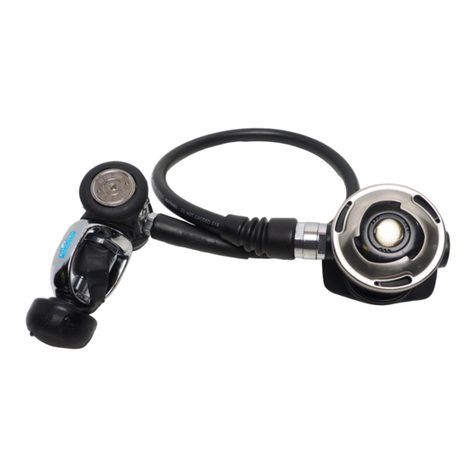
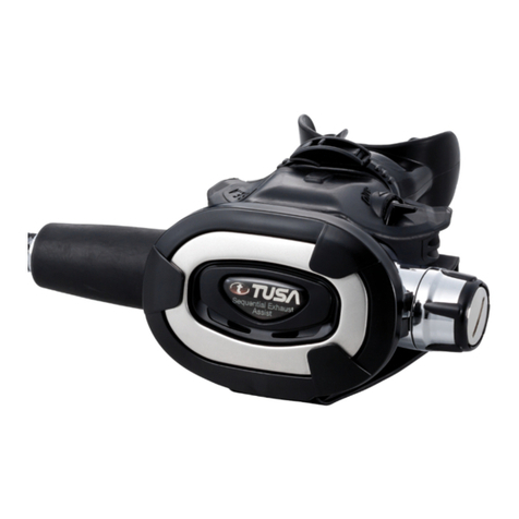
Tusa PLATINA R-100 User manual

R-100
BALANCED PISTON FIRST STAGE REGULATOR
R-100 FIRST STAGE
TECHNICAL MANUAL
Revised v1.0-2000 1

R-100
BALANCED PISTON FIRST STAGE REGULATOR
INDEX
SECTION PAGE NO.
IGENERAL INFORMATION 3
1.0 Important Information 3
1.1 Lubricants and Sealants 3
1.2 Tools Required 4
II DESCRIPTION AN OPERATION 5
2.0 Terminology Description of Operation 5
2.1 Balanced Piston First Stage 5
III GENERAL (USER) RECOMMENDED MAINTENANCE 7
3.0 General Care Guidelines 7
3.1 Determining Service Intervals Cycle life 8
3.2 Determining Service Application 9
(A) Exposure of Equipment 9
(B) User Maintenance 9
(C) Experience and Application 9
(D) Future Application 9
IV INSPECTION TECHNIQUES AND TROUBLESHOOTING 10
4.0 Inspection Techniques 10
(A) O-rings 10
(B) Sealing Surfaces 10
(C) Hoses Rubber Components 11
4.1 Troubleshooting Guidance 11
4.2 Troubleshooting 12
VDISASSEMBLY/ASSEMBLY 13
5.0 Disassembly Procedure 13
5.1 General Cleaning Methods 18
5.1 Repair Replacement Schedule 19
5.1 Assembly 20
5.1 Schematic Diagram FOLD OUT
VI TUNING AND ADJUSTMENT 24
6.0 Tuning and Adjusting Balanced Piston 24
6.1 Torque Specifications for R-100 26
VII SPECIAL APPLICATIONS GUIDANCE 27
7.0 Performance Specifications 27
7.1 Maximum Performance Adjustments 27
7.2 Enhanced Air Mixtures Approved Modifications 27
7.3 Cold Water Diving 27
7.4 Contaminated Water Diving 27
Revised v1.0-2000 2

R-100
BALANCED PISTON FIRST STAGE REGULATOR
GENERAL INFORMATION
SECTION I
1.0 I PORTANT INFOR ATION
This manual is designed for use by authorised service technicians who have
completed a training course in TUSA Regulator repair. This manual is intended
for use only in connection with the TUSA Regulator Repair course as prescribed
by Tabata Co., Ltd and is not meant for general distribution. Accordingly, Tabata
Co., Ltd makes no representations or warranties or any kind concerning the
techniques or procedures contained within this manual. It is assumed the
authorised service personal repairing and servicing regulators have average
mechanical ability, a good understanding of the operation of SCUBA regulators
and adequate diving experience.
This manual is not intended for use by divers in overhauling or attempted repair
of regulators in the field. Such practice by untrained persons is strongly
discouraged and should be attempted only by trained personnel when absolutely
necessary.
Copyright 2000 by Tabata Co., Ltd.
All rights reserved. The content of this manual constitutes the confidential
information of Tabata Co., Ltd. Its receipt or possession does not convey any
right to reproduce all or any portion or specification hereof, without the expressed
written consent of Tabata Co., Ltd. All publisher rights under the copyright law will
be strictly enforced.
1.1 LUBRICANTS AND SEALANTS
This regulator is approved for a
food grade (pure) type of silicone
grease or perfluoropolyether grease
(CHRISTO-LUBE MCG 111,
DC111) lubricant only.
When using a thread locking
compound we recommend Loctite
No. 242, 243 or 4013 medical.
Sources for these compounds may
be obtained from your TUSA factory
service centre.
See Figure 1.a
Revised v1.0-2000 3
FIG 1.a

R-100
BALANCED PISTON FIRST STAGE REGULATOR
GENERAL INFORMATION
1.2 TOOLS REQUIRED
The following tools are recommended for servicing the R-100 regulators. Some
tools listed are available from local sources. Special tools can be purchased upon
request from the TUSA Technical Service Department using the indicated
catalogue number.
ITE CATALOGUE NO. DESCRIPTION
1 Open end wrench, 1/2”-9/16”
2 Open end wrench, 11/16”-19/32”
3 Open end wrench, 5/8”-3/4”
4 MT-6W1 Allen Key, 3/16”
5 MT-6W2 Allen Key, 5/32”
6 MT4-10 Snap ring pliers
7 MT1-1 R-100 Piston bullet
8 MT1-2 Filter Retaining Bit
9 MT1-3 R-100 Piston stem o-ring guide
10 MT1-4 Tightening Bars (2/set)
11 MT-TW50N Torque wrench TW50N
12 MT-SH25.4 Spanner head 25.4mm
13 MT-26NTD Torque driver RTD260CN
14 Toothbrush, nylon bristle
15 O-rings pick, nylon or soft brass
16 BRASSPICK Brass pick set (2 picks)
17 12”-300mm adjustable wrench
Revised v1.0-2000 4
12
11
17
54
14
15
16
3
2
1
7
6
9
8
13 10

R-100
BALANCED PISTON FIRST STAGE REGULATOR
DESCRIPTION AND OPERATION
SECTION II
2.0 TER INOLOGY AND DESCRIPTION OF OPERATION
The following discussion will introduce the proper terminology to be used through
the manual. To help establish efficient communications when reporting problems
to the factory or discussions with the customer we recommend that you utilize
these terms. Terms will be introduced in full text followed by the acronym or
abbreviation in brackets.
The regulator reduces high-pressure air from the scuba cylinder (supply
pressure) to ambient pressure suitable breathing, through the operation of first
and second stage regulators. The first stage regulator reduces incoming high
pressure (HP) air, to an intermediate pressure (IP) of approximately 130 to 145
pounds per square inch (psi). The second stage regulator is a diaphragm
operated downstream demand valve and functions to reduce air from
intermediate pressure to ambient pressure permitting normal breathing at depth.
A low-pressure (LP) hose connects the first and second stages of the regulator. A
yoke on the first stage body secures the regulator to the cylinder valve, while an
o-ring surrounding the outlet orifice on the cylinder valve ensures an airtight
connection to the first stage. During servicing and overhaul, the term supply
pressure is used to denote an air supply of high pressure between 2750 to 3000
psi.
2.1 BALANCED PISTON FIRST STAGE
Refer to Figure 2-a and 2-b for the following discussion. High-pressure air
entering the yoke retainer inlet port of the first stage regulator passes through a
sintered filter which helps prevent the entry of any foreign particles. This airflow
continues through the regulator body passages to the HP seat chamber where it
flows across the annular gap between the HP seat and the need of the HP piston
stem. Here the air expands resulting in a reduction of pressure. Airflow continues
past the HP seat, as long as the piston remains in an OPEN position, and passes
through the internal section of the HP piston stem. The term “flow through piston”
describes this operation. Air merges form the HP piston stem and enters the
intermediate pressure chamber inside the upper portion of the cap and swivel.
The LP hoses are attached to the swivel and guide airflow to the second stage
regulator or buoyancy compensator inflator device.
The forces which tend to maintain the HP piston in the OPEN position are (1) the
force of the HP spring and (2) the force produced by ambient water pressure
acting on the back surface of the HP piston head. The force, which tends to move
the piston to the CLOSED position is the pneumatic force produced by the
intermediate pressure acting on the front of the piston head. The regulator is
designed so that the piston remains in the open position until the intermediate
pressure approaches approximately 135 psi. When this intermediate pressure is
achieved the force becomes great enough to overcome the force of the HP
spring and the ambient water pressure allowing the piston to move into the
CLOSED position sealing against the HP seat.
Revised v1.0-2000 5

R-100
BALANCED PISTON FIRST STAGE REGULATOR
DESCRIPTION AND OPERATION
The piston will remain in the CLOSED position until the intermediate pressure in
the LP hose is lowered by the actuation of the demand lever in the second stage
regulator during inhalation. This lowering reduces the pneumatic force acting
against the front of the HP piston head which permits the combined force of the
HP spring and the ambient water pressure to move the HP piston to the OPEN
position allowing high pressure air to flow into the swivel chamber again.
The first stage piston is pneumatically “balanced” meaning that the high pressure
air surrounding it exerts no opening or closing force against the piston itself. The
advantage of a “balanced” piston is that the first stage regulator maintains a
stable intermediate pressures range of 128 to 150 psi over ambient pressure,
despite a continually decreasing supply pressure from the SCUBA cylinder. This
stabilization of intermediate air pressure in the first stage assures optimal second
stage performance as the air supply in the SCUBA cylinder is depleted.
The balanced piston first stage of the R-100 Regulator functions to deliver the
intermediate pressure at 135 to 145 psi above the depth related ambient
pressure. This depth compensation is achieved by allowing ambient water to
enter the main body and flood the HP spring area and act upon the back side of
the HP piston. As the diver descends the ambient water pressure becomes the
reference point from which the HP piston controls the intermediate pressure from
135 to 145 psi above ambient pressure. The balanced piston first stage
maintains a constant differential between surrounding ambient water pressure
and intermediate air pressure. This helps to assure that the effort to actuate the
second stage will remain relatively constant with changing depth.
Revised v1.0-2000 6
FIG. 2-bFIG. 2-a
CLOSED POSITION OPEN POSITION

R-100
BALANCED PISTON FIRST STAGE REGULATOR
GENERAL (USER) RECOMMENDED MAINTENANCE
SECTION III
3.0 GENERAL CARE GUIDELINES
Tusa recommends to all Authorised Dealers that they take individual time with
each customer to explain and demonstrate the following simple steps for care
and maintenance of the regulator. This will help to ensure the following goals:
Personalised contact with the customer insuring satisfaction.
Help to insure long life of the new purchase through maintenance.
Communication of findings during tuning or overhaul service.
Help prevent problems described if this step is not taken.
1. After exiting the water and with the cylinder valve still on, purge air
through the second stage to help blow out remaining water.
1. Close cylinder valve and purge remaining pressure from the regulator.
Loosen the yoke knob and remove the first stage from the valve. Crack
the valve slightly to direct a stream of air onto the dust cap to dry it off.
Immediately place the dry dust cap over the conical filter and tighten the
yoke knob to prevent moisture from entering the first stage. The conical
filter is a nickel-plated sintered brass component whose metallic matrix
structure creates a large filtration area allowing for efficient air filtration
with low-pressure drop. This large area makes the filter susceptible to
corrosion by trapping tiny droplets of water within it’s matrix.
1. Prior to rinsing the regulator insure the dust cap is snug and covering the
conical filter area of the yoke. If using the S-30 Platina adjustable second
stage, dial the adjustable knob fully clockwise in to prevent water from
entering into the hose and first stage.
1. Using either of the following rinse methods if necessary. A stream of fresh
water, from a hose or tap, directed around and especially into the holes in
the first stage will flush salt water from the piston and spring area
preventing corrosion and minimal deposits. Direct fresh water into the
mouthpiece of the second stage to flush the internal components,
diaphragm and exhaust valve area. The build up of mineral (salt) deposits
will lead to premature wear on the o-rings of the first stage piston and
lead to a rough breathing second stage valve mechanism.
OR
Immerse the regulator (make sure dust cap in place) into a bath of fresh water
and agitate to insure good flushing. If extended storage is anticipated, immersion
for 12 hours or more is preferred. After immersion, utilize the rinse step above to
flush all regulator components thoroughly.
Revised v1.0-2000 7

R-100
BALANCED PISTON FIRST STAGE REGULATOR
GENERAL (USER) RECOMMENDED MAINTENANCE
NOTE
Do not depress the purge button of the second stage while rinsing or soaking.
This will help prevent water from entering the valve mechanism or intermediate
pressure hose causing corrosion or deposits
1. Before storing the regulator, hang it with the second stage down to insure
drainage and ample time to completely dry all components. If a cylinder is
available, the user may wish to install the regulator and purge air through
the system to insure no water remains within the valve mechanism prior
to storage.
E PHASIZE THE FOLLOWING TO YOUR CUSTO ERS:
DO NOT expose the regulator to extreme heat or direct sunlight when not in use.
Temperatures exceeding 80oC (180oF) for extend periods of time may cause
permanent damage to some internal valve components leading to a lack of
performance or failure. If you suspect your regulator has been exposed to
excessive heat, please have it examined by your authorised TUSA service
centre.
DO NOT leave the regulator pressurized or attached to a SCUBA cylinder for an
extended period of time when not in use.
DO NOT lift the SCUBA cylinder by using the regulator hoses or first stage as a
handle. Always secure the cylinder to prevent it from tipping over and damaging
the regulator while it is attached.
3.1 DETER INING SERVICE INTERVALS AND CYCLE LIFE
TUSA recommends that the Service Technician utilize the following guidelines to
determine service intervals and extent of service required for the customers’
regulator. Most components in a regulator have very high expected usable life
based on the number of breathing cycles and exposure of the equipment.
The following calculation is meant to educate the Service Technician on how
many cycles (breathing) a regulator may see from average use.
CYCLES = No. of DIVE DAYS per YEAR X No. of DIVE HOURS per DAY
X 20 BREATHS per MINUTE X 60 MIN per HOUR
For example: If you dived 25 days last year for 3 hours per day:
CYCLES =
25 DAYS/YEAR X 3 HOURS/DAY X 20 BREATHS/MIN X 60 MIN/HOUR
CYCLES = 25 X 3 X 20 X 60
BREATHING CYCLES = 90,000 PER YEAR
Revised v1.0-2000 8

R-100
BALANCED PISTON FIRST STAGE REGULATOR
GENERAL (USER) RECOMMENDED MAINTENANCE
3.2 DETER INING SERVICE APPLICATION
As you can see it is important to determine your customers dive habits to
determine the best possible recommendation for service. Other factors to
consider include the exposure of the equipment, extent of user maintenance,
experience and application from the user and future planned use of the
equipment. To summarise:
(A) EXPOSURE OF EQUIP ENT
Diving cold water 4.5oC (40oF or lower) requires the regulator to be
“Environmentalised” or protected from potential freezing and requires more
frequent servicing (See section 7.3).
Diving in low visibility or contaminated water requires more frequent servicing
and overhaul to keep residue from building up inside the valve components. (See
section 7.4)
Diving in tropic salt-water environments tends to subject the regulator to constant
moisture exposure and will lead to accelerated corrosion of regulator valve
components.
Diving with Enhanced Air (Safe Air) mixtures requires the regulator to be
specially cleaned and lubricated. (See section 7.2)
(B) USER AINTENANCE
Obviously a regulator that has been maintained extensively by the user will
require far less overhauls to replace worn or corroded components. Poor user
maintenance indicates that more attention (overhauls and tuning) of the regulator
is required to prevent failures.
(C) EXPERIENCE AND APPLICATION
Deep diving or overhead environment diving requires a regulator to be in top
condition at all times. The experienced user would require more frequent
overhauls and replacement of key o-rings and first stage spring to maximise
reliability.
(D) FUTURE APPLICATION
A user planning an extended dive vacation, training or use for applications
discussed above would benefit from an overhaul prior to the planned extended
use to insure maximum performance and reliability.
Revised v1.0-2000 9

R-100
BALANCED PISTON FIRST STAGE REGULATOR
INSPECTION TECHNIQUES AND TROUBLESHOOTING
SECTION IV
4.0 INSPECTION TECHNIQUES
We encourage the service technician to develop good habits and practice in
inspection techniques during service and overhaul. Observing the exterior
condition of a regulator can offer clues on what may be found during overhaul.
Finding sand or salt deposits on the exterior crevices between mating parts may
indicate a regulator that is not properly maintained by the customer. One may
almost certainly discover more sand or salt deposits inside the second stage
case. In severe instances, a major overhaul and adjustment would probably take
less time to accomplish than to attempt a light cleanup leading to marginal
performance adjustment. Severe dings in the chrome plated brass body of the
first stage or plastic case of the second stage may indicate gross negligence in
handling the regulator. Further examination must proceed especially looking for
small cracks or damage in the second stage body, LP hoses, yoke knobs etc. It is
most important to look for cracks or damage near the external nut of the demand
housing in the second stage case. Mishandling may lead to severe stress
imparted into the LP hose resulting in cracks. Please refer to disassembly of the
stages for further discussion.
(A) O-RINGS
O-rings are common off-the-shelf well-engineered reliable sealing devices. A few
words about handling them are required. O-rings can be ordered in different
sizes, rubber compounds and hardness (durometer). It is important not to
substitute o-rings from other sources in replacing TUSA regulator seals. Use only
factory supplied o-rings. As part of the TUSA annual servicing policy it is
recommended that all o-rings be replaced to maintain warranty. Further details
are available from the factory distributor. Do not attempt to clean or lubricate o-
rings outside of the recommendations in Section 5.1.
(B) SEALING SURFACES
All metal parts use in TUSA regulators are made of either a corrosion resistant
stainless steel or chrome plated brass. Handle all metal components with care to
avoid scratches, dings or dents. Some components such as the first stage piston
in the R-100 have a very smooth and polished surface on the stem. This is the
sealing surface for the HP o-ring. A very unnoticeable scratch or ding on this
surface may allow a high-pressure leak across the o-ring. The piston cannot be
repaired and thus becomes an expensive replacement, which could have been
avoided by proper handling. Pay particular attention to the assembly of all
components and which surfaces are used for sealing against o-rings. Handle
these surfaces with particular care to avoid scratches, dings or dents.
Revised v1.0-2000 10

R-100
BALANCED PISTON FIRST STAGE REGULATOR
INSPECTION TECHNIQUES AND TROUBLESHOOTING
(C) HOSES AND RUBBER CO PONENTS
The examination, care and handling of all rubber components are well
documented through out the TUSA Dealer Service Manual. Look for
deterioration and cracking of rubber components resulting from age,
misuse, or exposure to caustic cleaning compounds. Contact your factory
representative should you have further questions.
4.1 TROUBLESHOOTING GUIDANCE
Prior to troubleshooting the R-100 regulator we recommend you become familiar
with the operation and design by reading Sections 2.0 and 5.0 through to 6.0.
You will find that a good basis and understanding of the regulator function will
benefit your repair and servicing abilities.
Prior to beginning a service or troubleshooting session it is important to proceed
as follows:
1. Talk to the customer. Attempt to understand the nature of the problem. If
the customer describes for instance, “sporadic periods of high inhalation
efforts”. Ask the obvious question: “Did you happen to be swimming
upside down when the regulator seemed to breathe harder?” Discussions
may lead to understanding your customer and their complaints better.
1. Attempt to duplicate the functional problem by doing an In-Water Test. A
reported leak or bubble from the first stage may be traced to a specific o-
ring much quicker with this method.
1. Record your findings as you examine and test the regulator prior to and
during the entire service and overhaul procedure. Record the customers
name, date of last service, intermediate pressure before and after service,
supply pressure during testing, unusual conditions or debris present,
components and seals replaced during this service, approximate
breathing cycles between service periods and any other pertinent
information.
Revised v1.0-2000 11

R-100
BALANCED PISTON FIRST STAGE REGULATOR
INSPECTION TECHNIQUES AND TROUBLESHOOTING
4.2 TROUBLESHOOTING R-100 BALANCED PISTON FIRST STAGE
SYMPTON POSSIBLE CAUSES RECOMMENDATIONS
LOW FLOW OR HIGH INHALATION EFFORTS
1 Cylinder valve not open or clogged 1 Open valve completely or overhaul needed
2 Sintered filter (5) clogged 2 Replace sintered filter
3 HP spring (18) coil weak or fatigued 3 Replace HP spring
INTER EDIATE PRESSURE LOW OR UNSTABLE
1 HP piston head o-ring (20) damaged 1 Replace o-ring, check seal worn or
damaged
2 HP piston (19) sealing edge or HP seat
(8) damaged
2 Replace HP piston and HP seat
3 Spring isolator (17) installed incorrectly
or wrong size
3 Replace Spring isolator
4 HP piston stem o-ring (12) worn or
Damaged.
4 Replace o-ring and check seal
5 Filter housing (7) loose 5 Tighten filter housing
6 Leak between intermediate chamber,
LP hose and second stage
6 Find leak in-water test and replace
damaged o-ring.
7 End cap (22) loose 7 Tighten cap
INTER EDIATE PRESSURE EXCESSIVELY HIGH
1 HP Piston (19) sealing edge or HP seat
(8) damaged.
1 Replace HP seat check
HP piston sealing edge
2 Spring isolator (17) installed
Incorrectly or wrong size.
2 Replace isolator.
3 HP piston o-rings (12) (20)
Are worn or damaged.
3 Replace o-rings, check seal.
AIR LEAKS DETECTED FRO IN-WATER TEST
1 HP piston o-rings (12) (20)
Are worn or damaged.
1 Replace o-rings, check seal.
2 End cap o-ring (16) is worn. 2 Follow special procedure
Section 5.1 5.3 only.
3 LP port plug o-rings (24)
Are worn or damaged.
3 Replace o-rings, check seal.
Revised v1.0-2000 12

R-100
BALANCED PISTON FIRST STAGE REGULATOR
DISASSEMBLY / ASSEMBLY
SECTION V
NOTE
Prior to disassembly, record the results of the preliminary inspection, the in water test,
and the first stage intermediate pressure. Remember to retain all o-rings, filters or other
components that are to be replaced in case the customer requests to view the parts. For
replacements, that were part of the Warranty scheme annual service, please return
these parts to your TUSA factory distributor along with a copy of the service report.
Remember to record your findings as you proceed to allow both a complete record of the
overhaul and future reference for servicing. The words “RECORD FOR
REPLACEMENT” will indicate all components to be handled in this manner.
Read and understand the Troubleshooting Section 4.0 to gain a better idea of which
internal parts may be worn, and to better advise your customer of the service that is
required. Refer all item numbers (99) to the “schematic” view or exploded view for this
regulator found at the end of Section 5.3.
5.0 DISASSE BLY PROCEDURE R-100 BALANCED PISTON FIRST STAGE
1. Before disassembling the first stage,
remove all attached hoses.
Remember to use the proper wrench
with each hose as required: low
pressure second stage hoses use a
9/16” open end wrench, low pressure
inflator hose use either a 9/16” or _”
open end wrench, and the high
pressure gauge hose users a 5/8”
open end wrench. Refer to
Figure. 5-a
1. Remove all LP plugs (23) from end
cap (22), all HP Plugs (10) and all EP
Plugs (15) from body (13) using
correct Allen key. Remove o-rings
(24) from LP plugs and o-rings (11)
from HP plugs inspect o-rings for any
sign of decay. RECORD
REPLACEMENT IF REQUIRED.
Refer to Figure. 5-b
Revised v1.0-2000 13
FIG. 5-a
FIG. 5-b

R-100
BALANCED PISTON FIRST STAGE REGULATOR
DISASSEMBLY / ASSEMBLY
3. Prepare to remove the End-cap (22)
by inserting one LP tightening bar
into one of LP port in the end cap
and one HP tightening bar into one of
the HP ports in the body (13) Refer
to Figure. 5-c
NOTE
Make certain the Tightening Bars are firmly seated into both plugs (23) (10) before
attempting to rotate the end cap (22) in a counterclockwise direction.
4. Holding the regulator firmly in place,
twist the end cap (22) in a counter
clockwise direction until the end cap
(22) is loosened enough to complete
removal by hand. The end cap ring
(21) should then be taken from the
body by hand, inspected and
cleaned. Refer to Figure. 5-d
5. Using an o-ring pick remove the body
o-ring (16) RECORD FOR
REPLACEMENT. DO NOT attempt to
reuse this o-ring.
6. Remove the HP piston (19) from
body (13) by carefully grasping the
piston between thumb and forefinger,
pulling straight up with a slow, steady
force.
Refer to Figure. 5-e
WARNING
Failure to recognize or replace a faulty HP piston may lead to failure of the
regulator to regulate the intermediate pressure. Use prudence and replace the
piston if damage to the piston stem sealing (knife) edge is found.
Revised v1.0-2000 14
FIG. 5-d
FIG. 5-e
FIG. 5-c

FIG. 5-h
FIG. 5-g
FIG. 5-f
R-100
BALANCED PISTON FIRST STAGE REGULATOR
DISASSEMBLY / ASSEMBLY
7. Remove any spring isolators (17)
(using a pneumatic air gun) from the
base of the piston head and inspect
this area for signs of corrosion See
Figure. 5-f. Also inspect the piston
stem for unusual scratches, dings,
dents or wear along its sealing
surface. Closely insect the sealing
edge of the piston stem for dings or
dents. Record your findings on the
condition of the piston. RECORD
FOR REPLACEMENT and DO NOT
attempt to reuse if any of these
conditions are found.
8. Remove the HP spring (18) and
inspect it for any unusual cracks,
corrosion or bent coils. RECORD
FOR REPLACEMENT and DO NOT
attempt to re-use if any of these
conditions are found. Refer to Figure
5-g
WARNING
Failure to recognize or replace a faulty HP spring may lead to failure of the
regulator to supply air. Use prudence and replace the spring regularly to maintain
top performance in the regulator function.
9. Remove the piston head o-ring (20)
and RECORD FOR
REPLACEMENT. DO NOT attempt
to reuse this o-ring Figure 5-h. If the
piston is to be reused, take steps at
this time to protect the piston stem
and sealing edge from damage
during handling and cleaning.
Revised v1.0-2000 15

FIG. 5-i
FIG. 5-j
FIG. 5-k
R-100
BALANCED PISTON FIRST STAGE REGULATOR
DISASSEMBLY / ASSEMBLY
10. Removal the piston stem o-ring (12)
located within the internal o-ring
groove of the main body (13), but
must be attempted using only the
proper tools and patience. View the
main body through the piston
entrance to locate the internal o-ring
groove. The piston stem o-ring (12)
seals against both the stem of the HP
piston (19) and the brass internal o-
ring groove within the main body.
Refer to Figure 5-i.
NOTE
Extreme care must be taken not to damage the brass sealing surface of the groove
when removing or installing this o-ring. Use only soft brass or plastic o-ring pick to
attempt this operation. Examine the o-ring upon removal and RECORD
REPLACEMENT. DO NOT attempt to reuse this o-ring.
11. Remove the Yoke knob (1) and the
dust cap (3) from the yoke (2).
Inspect very thoroughly for cracks,
wearing, or distortion. Also check the
internal thread located on the yoke.
RECORD REPLACEMENT IF
REQUIRED. Refer to Figure 5-j.
12. Remove and inspect the yoke for any
signs of distortion or cracking. If none
are present and the yoke shows no
signs of deterioration, it need not be
removed to service the first stage.
12. To remove the yoke (2) from the
main body (13), we recommend
using a slotted flat bar tool or a 12”
adjustable wrench. Place the first
stage in a smooth-jawed vise, with
yoke facing up. Install the wrench or
flat bar tool onto the yoke retainer
(14). Using firm, steady force, rotate
the tool in a counterclockwise
direction until the yoke retainer nut
and yoke are removed. See Figure
5-k
Revised v1.0-2000 16

FIG. 5-l
FIG. 5-m
R-100
BALANCED PISTON FIRST STAGE REGULATOR
DISASSEMBLY / ASSEMBLY
NOTE
Use care and caution to avoid damage to the surface of the body (13). DO NOT over-
tighten the vise onto the soft brass of the first stage.
14. To remove the conical filter (5), first
remove the filter retainer assembly
with 3/8” Allen key. Use snap ring
pliers to remove the filter retaining
ring (4) from the housing (7). The
conical filter and the filter o-ring (6)
should drop in your hand. Examine
and record the condition of the
conical filter looking for large
particles of rust, debris, corrosion, or
dark deposits from excessive
contamination. RECORD FOR
REPLACEMENT and DO NOT
attempt to reuse. Refer to Figure 5-l
15. To remove the HP seat (8) and HP
seat retainer (9) turn the body (13)
upside down. See Figure 5-m. If the
HP seat assembly does not dislodge
and fall out by itself, push it out from
opposite end using a short burst air
from an LP air gun. Examine and
record your findings on the condition
of the HP seat looking for deep
indentations, contamination, severe
discolouration or debris. RECORD
FOR REPLACEMENT and DO NOT
attempt to reuse the HP seat if any of
these conditions are found. See
Section 4.0 for important guidelines.
NOTE
DO NOT attempt to remove the HP seat from the body by inserting any sharp
instrument. Doing so will cause damage.
16. Use a nylon bristle brush or toothbrush to remove any Loctite. Residue will be
found on the threads or yoke retainer nut (14) and main body (13). It is important
to do this prior to cleaning.
This concludes the disassembly of the R-100 balanced piston first stage.
Revised v1.0-2000 17

R-100
BALANCED PISTON FIRST STAGE REGULATOR
DISASSEMBLY / ASSEMBLY
5.1 GENERAL CLEANING ETHODS
Authorised TUSA Service and Repair technicians shall heed all warnings on the service
and cleaning of all plastic parts in order to prevent failures. The design and performance
of regulators has advanced significantly within the past 10 years. Advances in materials
Science has led to the use of engineered plastic polymers and thermoplastic resin alloys
replacing traditional metal components.
All metal parts used in TUSA regulators are made of either a corrosion resistant
stainless steel or chrome plated brass. Handle all metal components with care to avoid
scratches, dings or dents.
We recommend using a mild yet effective cleaning solution for removing salt deposits,
grease and dirt from all metal components. We recommend using a cleaning solution
similar to Oakite #31 or VFC-23 and a small ultrasonic cleaner for most parts plastic
metal. You may substitute a mild dish soap or diluted household grade of white distilled
vinegar.
Other exterior cleaning can be accomplished using isopropyl (alcohol) where required.
Use only clean lint-free wipes and cotton applicators for all cleaning requirements.
WARNING
DO NOT use any acids or hydrocarbon based cleaning solutions on any plastic or
metallic components of the regulator. Some spray-on products may contain
hydrocarbon-based propellants that may chemically attack or otherwise degrade
some of the materials used in the manufacture of the regulator.
DO NOT use any AR OR-ALL or vinyl restoration type liquids in an attempt to
improve the appearance of the regulator.
DO NOT use silicone-based liquids, grease or sprays on the exterior surfaces of
the regulator in an attempt to restore appearance.
DO NOT use any RTV silicone or silicone sealant type products to attempt repair
on any regulator components.
DO NOT attempt to clean any parts by poking sharp objects into holes. Failure to
heed these warnings may lead to damage or failure of regulator components.
Revised v1.0-2000 18

R-100
BALANCED PISTON FIRST STAGE REGULATOR
DISASSEMBLY / ASSEMBLY
5.2 REPAIR AND REPLACE ENT SCHEDULE
The following repair and replacement schedule is recommended for the R-100 Balanced
Piston First Stage. Tusa recommends full replacement of all soft seals (o-rings seats)
according to service use and cycle life of the regulator as discussed in Section 3.0.
Annual service requires replacement of all soft seals at a minimum of I year and 6
months for regulators in rental, dive school or commercial applications.
ANNUAL OVERHAUL REPAIR KIT RS110/130 FIRST STAGE
Product Code Description Remarks Qty
R100-020 FILTER 1
010 O-RING BS010 1
R100-040 HP SEAT 1
012 O-RING BS012 1
009 O-RING BS009 1
S30 O-RING 30x2 1
020 O-RING BS020 1
011 O-RING BS011 2
The mandatory replacement of the HP spring (18) is required after a maximum life of
750,000 (seven hundred and fifty thousand) cycles based on excessive exposure to
corrosion of high performance use. Refer below for a view of all soft seals and hardware.
Revised v1.0-2000 19

R-100
BALANCED PISTON FIRST STAGE REGULATOR
DISASSEMBLY / ASSEMBLY
5.3 ASSE BLY R-100 BALANCED PISTON FIRST STAGE
NOTE
Prior to assembly, ensure that all parts have been inspected (both new and those that
are being reused) and are of top quality. Ensure that all o-rings are clean, supple and
lubricated as described in Section 5.1. Double check to make sure all o-rings are of the
proper size and installed per this procedure.
1. Install the HP piston stem o-ring (12)
into the main body (13) using the
R100 piston stem o-ring guide tool
and a blunt o-ring pick. Use the pick
from the piston end of the body and
the guide tool from the HP seat side.
Manipulate the o-ring into the internal
groove of the main body. Lubricate
this o-ring with Christolube before
installing. Refer to Figure 5-n
NOTE
Replacement of the piston stem o-ring (12) located within the internal o-ring groove of
the main body (13) must be attempted using only the proper tools and patience. View
the main body through the piston entrance to locate the internal o-ring groove. The
piston stem o-ring (12) seals against both the stem of the HP piston (19) and the brass
internal o-ring groove within the main body. Extreme care must be taken not to damage
the brass sealing surface of the groove when removing or installing this o-ring.
2. Lubricate and install the piston head o-ring (20) onto the head of the piston (19).
WARNING
Failure to recognize or replace a faulty HP piston may lead to failure of the
regulator to regulate the intermediate pressure. Use prudence and replace the
piston if damage to the piston stem sealing (knife) edge is found.
3. Apply a light film of lubricant (see
section 1.1) to both sides of the
spring isolator (17). Install over the
piston stem onto the head of the
piston. See Figure 5-o. Then apply a
light film of lubricant to both sides of
another (if required) spring isolator
(17), install into the spring cavity of
the main body. Use a blunt object to
position the spring isolator down flat.
Revised v1.0-2000 20
FIG. 5-n
FIG. 5-o
Table of contents
Other Tusa Controllers manuals
Popular Controllers manuals by other brands

Siemens
Siemens ICP-B6 Installation instructions manual

Mankenberg
Mankenberg UV 3.5 ATEX H2 Original operating manual

TAOS
TAOS TSL2571 EVM2 Kit quick start guide

ABB
ABB ACS550-01 user manual

American Lighting
American Lighting LED-RGB-CTRL-24V installation instructions

wibutler
wibutler Z-Wave Controller user manual

Danfoss
Danfoss PLUS+1 SC0XX-1 Series technical information

KE2
KE2 Evaporator Efficiency Step-by-Step QuickStart

Buderus
Buderus Logamatic BC10 Operating and service instructions

Clinton
Clinton 8890BH Service manual

LSIS
LSIS MASTER-K200S Instructions & Programming

Solcon
Solcon HRVS-DN series instruction manual