ensto enervent Plaza eco EDA User manual

Ventilation unit with heat recovery
Planning, installation and operational instructions manual
www.enervent.
EDA
Enervent Digital Automation
This instruction covers all ventilation units with EDA-control.
Before installing and operating this unit,
please read this manual thoroughly, and retain it for further reference.

2
TABLE OF CONTENTS
TABLE OF CONTENTS
OVERVIEW
WARNING 3
TYPE MARKING 3
TYPE DESCRIPTION 4
FOREWORD 4
OPERATING PRINCIPLE 4
DUCT HEAT INSULATION 5
INSTALLATION
EQUIPMENT 6
INSTALLATION 6
DRAINING THE VENTILATION UNIT 8
DEFINING ADDRESSES FOR OPERATING PANELS 9
USER GUIDE
STARTING THE UNIT 10
SUPPLY AND EXTRACT AIR CALIBRATION 10
OVERVIEW ON VENTILATION 10
CONTROL PANEL AND CONTROL 11
MAINTENANCE
MAINTENANCE 25
FAULT ALARMS 26
HEAT EXCHANGER BELT REPLACEMENT 27
TROUBLESHOOTING 28
TECHNICAL INFORMATION
TECHNICAL INFORMATION 30
DIMENSION DRAWINGS 31
HEAT RECOVERY EFFICIENCY 41
CHARACTERISTIC CURVES 44
CONTROL CHARTS AND WIRING DIAGRAMS 52
WATER COIL PRINCIPLE CHARTS 53
CONTROL CHARTS 54
WIRING DIAGRAMS 58
OUTER WIRING 67
INFORMATION ABOUT MODBUS 67
AIR FLOW REGULATION OF UNIT WITH EDA CONTROL 69
DECLARATION OF CONFORMITY 69
THE PARAMETERS OF EDA CONTROL 73
VENTILATION UNIT QUICK GUIDE
Copyright Enervent® 2013. All rights reserved.
3
Enervent EDA MD EN 2013_1
OVERVIEW
!
• Cut the power to the unit before opening the maintenance hatch!
After opening the maintenance hatch wait for two (2) minutes before starting the main-
tenance work! The fans rotate for a while even after the power is cut and the after heater
in EDE-models can be hot. There are no user-serviceable parts inside the control panel
or inside the electrical cabinet, leave the service of these parts to a professional. It is im-
portant during troubleshooting not to turn on the power to the unit before being as-
sured what the problem is.
• Theunitmustbedisconnectedfromtheelectricnetworkifvoltagetests,insulation
resistance measuring or other measurings/electrical work, which can harm sensitive
electronic equipment are done.
WARNING
• Theregulationandcontrolequipmentoftheunitcancauseleakagecurrent.Thereforethefaultcurrentprotec-
tion doesn’t always work correctly with the unit. The electrical connections must be made according to prevai-
ling local directives.
• AllventilationdeviceswithEDA-controlaretobeequippedwithovervoltageprotection.
• Ventilationsystemswithwatercoilshavetobeequippedwithdampersinordertopreventfreezing
of the coil during power cuts.
TYPE MARKING
Inside the ventilation unit is a type shield. Fill in the type shields data here to have it easily available when it is needed, e.g.
when buying new lters. Before you start reading, please check the type marking of the unit.
This manual covers the following units:
EnerventPlazaecoEDA
Enervent Pingvin eco EDA
Enervent Pingvin eco XL EDA
Enervent Pandion eco EDA
Enervent Pelican eco EDA
Enervent Pegasos eco EDA
Enervent Pegasos Cooler
Enervent Pegasos eco XL EDA
Enervent Pegasos XL Cooler
Enervent LTR-2 eco EDA
Enervent LTR-3 eco EDA
Enervent LTR-6 eco EDA
Enervent LTR-7 eco EDA
Enervent LTR-7 eco XL EDA
ilmastointilaite
ventilation unit
TYYPPI/TYPE:
SRJ.NRO/SERIAL NO:
W/ V/ HZ / A:
ENSTO ENERVENT OY
KIPINÄTIE 1 06150 PORVOO
TEL +358 (0)207 528800 FAX +358 (0) 207 528844

4
OVERVIEW
Enervent LTR-3 eco EDE - CG
TYPE DESCRIPTION
Ventilation unit
frame Choice of fan
(no markings
=alternative
current fans)
Control/possible
after heating
FOREWORD
All Enervent ventilation units are designed and manufactured for use all year round. In Finland the ventilation units have
been installed in houses and other spaces for over 20 years and their popularity is increasing each year. Because of the
knowledge and experience we have amassed during these years, we can now manufacture more energy ecient and user
friendly ventilation units. The Enervent unit series is the result of a long product development. All units in the series are
very versatile and exible.
eco Ventilation unit with direct current fans.
ED Ventilation unit with EDA control, without after heater.
EDE Ventilation unit with EDA control, with after heater.
EDW Ventilation unit with EDA control and water after heater. Delivery includes cooling coil and
freezeprotection,2-wayvalve,valveactuator,ducttemperaturesensorandatemperaturecontroller.
CG Cooling Geo (groundcooling) cooling equipment. Delivery includes water cooler, 3-way valve, valve
actuator and relay control for pump. Also read the separate CG-instruction.
CW Cooling Water water cooler. Delivery includes water cooler, 3-way valve and valve actuator.
CX Cooling Expansion evaporator. Delivery includes evaporator coil and control which prevents the com-
pressor from starting too often (the ouside unit is not included). Also read the separate CX-instruction.
EDX Combination of ventilation unit and heat pump. Delivery includes evaporator coil, electrical duct heater
and outside unit. The refrigerant piping is not included. Also read the separate EDX-instrction.
Cooler (CO) Ventilation unit with built-in cooling apparatus.
Possible cooling mode
OPERATING PRINCIPLE
The ventilation units are based on a regenerative heat recovery This is achieved with a rotating heat exchanger through
which incoming air and extract air ow in opposite direction. Aluminium foils within the heat exchanger transfer heat
from the extract air to the supply air. A characteristic of the regenerative heat exchanger is its high rate of heat recovery
(or eciency).
The eciency varies from 75% to 85%, depending on the proportion of supply air and extract air (the heat from the supply
air fan is taken into account). Thanks to their high eciency, the units save heating energy at the same time as they provide
excellent indoor air quality; therefore they pay themselves back in a relatively short time.
5
Enervent EDA MD EN 2013_1
OVERVIEW
DUCT HEAT INSULATION
Ventilation ducts must be thermally insulated to prevent water from condensing to the inner or external duct surfaces in any
circumstances. Additionally, the air temperature must not decrease or increase excessively in the ducts because of external fac-
tors. The ventilation engineer calculates the insulation requirements depending on the placement of the ducts and the air temperatu-
res.When the insulation materials are designed, it must be taken into account that the extract air temperature may decrease signicantly
belowzerodegrees.TheOptimizersoftware,whichisavailablefromEnstoEnervent’swebsite,canbeusedtocalculatetheextractair
temperature with dierent outside air temperatures. Calculation software available from insulation material manufacturers can also be
used when designing the insulation material thickness.
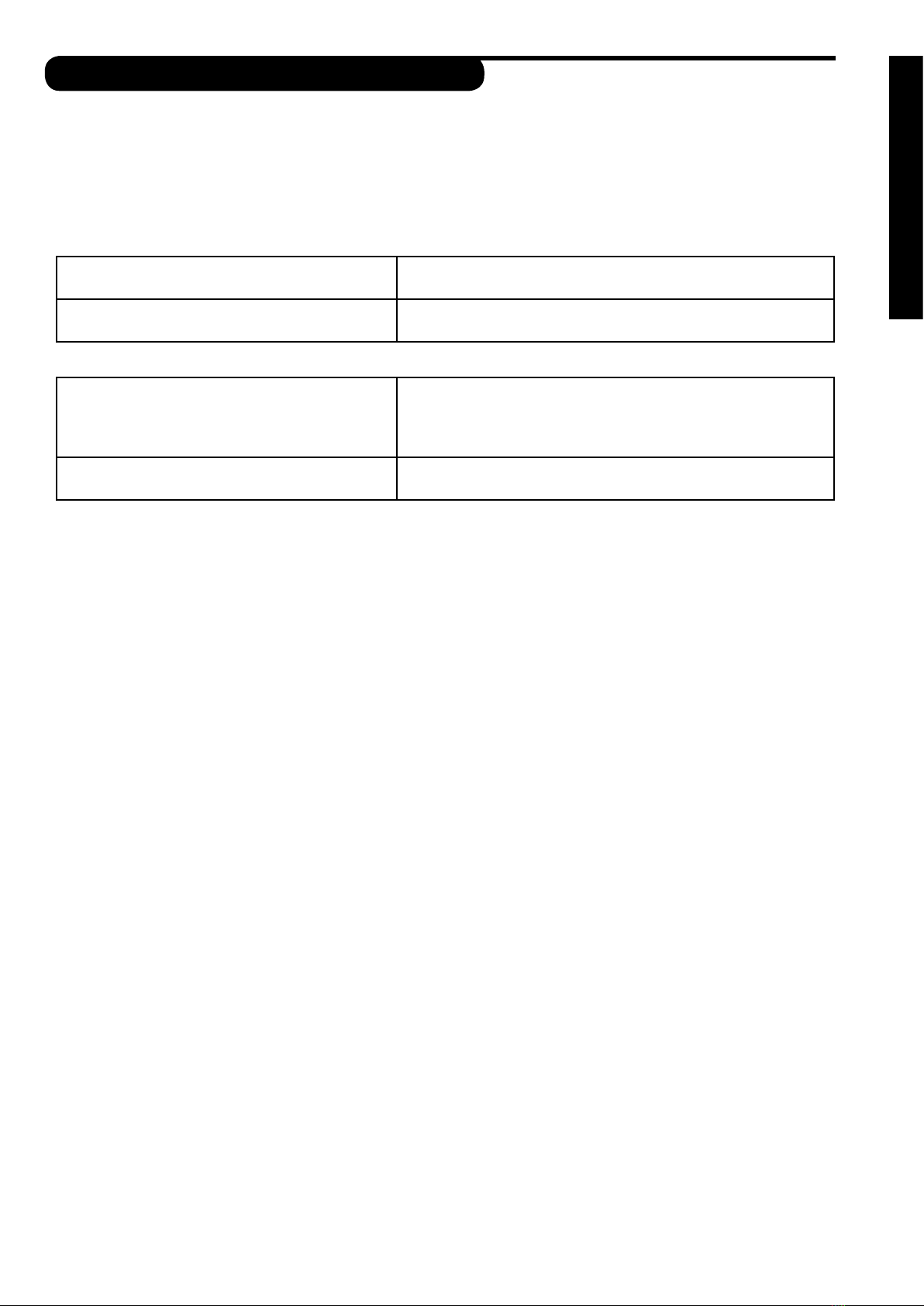
Table 1: Ventilation duct thermal insulation in heating use
Supply air duct from the ventilation unit to the
supply valve
The insulation must be designed and implemented so that the
maximum air temperature change in the duct is less than 1°C.
Extract air duct from the supply valve to the venti-
lation unit
The insulation must be designed and implemented so that the
maximum air temperature change in the duct is less than 1°C.
Table 2: Ventilation duct thermal insulation in cooling use
Supply air duct from the ventilation unit to the
supply valve
The insulation must be designed and implemented so that the
maximum air temperature change in the duct is less than 1°C. At
least 18 mm of cellular rubber insulation on the duct surface and
sucient additional insulation.
Extract air duct from the supply valve to the venti-
lation unit
The insulation must be designed and implemented so that the
maximum air temperature change in the duct is less than 1°C.
Ventilation Duct Insulation Examples:
Outside air duct (fresh air duct)
Cold spaces: 100 mm of sheet, mat, or pipe-covering insulation (plus the blown wool, when used).
Warm/semi-warm spaces*:
Option 1: 80 mm insulation with vapour-proof external surface
Option 2: 20 mm of cellular rubber insulation on the duct surface and 50 mm insulation with vapour-proof external surface.
The insulation must prevent water vapour from condensing to the external duct surface and excessive air temperature rise during sum-
mer.
Supply air duct
Cold/semi-warm spaces*:
In standard ventilation the insulation must be designed and implemented so that the maximum air temperature change in the duct is
less than 1°C. For example, 100 mm of sheet, mat, or pipe-covering insulation can be used (plus the blown wool, when used).
Warm spaces: Insulation is not required in standard ventilation.
In heating and cooling use see tables 1 and 2.
Extract air duct
Warm spaces: Insulation is not required in standard ventilation.
Cold/semi-warm spaces*:
In standard ventilation the insulation must be designed and implemented so that the maximum air temperature change in the duct is
less than 1°C. For example, 100 mm of sheet, mat, or pipe-covering insulation can be used (plus the blown wool, when used).
In heating and cooling use see tables 1 and 2.
Exhaust air duct
Cold spaces: 100 mm of sheet, mat, or pipe-covering insulation
Warm/semi-warm spaces:
Option 1: 80 mm insulation with vapour-proof external surface
Option 2: 20 mm of cellular rubber insulation on the duct surface and 50 mm insulation with vapour-proof external surface.
The insulation must prevent water vapour from condensing to the external and internal duct surfaces.
Circulation air duct
The insulation must be designed and implemented so that the maximum air temperature change in the duct is less than 1°C.**
*) A semi-warm space refers also to dropped ceilings, sub-oors, and casings.
**) When Kotilämpö systems are renewed, the recycling air duct can be left as it is.
Sound insulation is not taken into account in these insulation instructions and examples.

6
INSTALALTION
EQUIPMENT
INCLUDED IN THE DELIVERY OF THE UNIT:
1. Enervent ventilation unit
2. Control panel
3. Control panel cable RJ4P4C, length 20 m (installation in a min 16 mm conduit)
SEPARATELY SOLD EXTRA EQUIPMENT:
4. Extra control panels max. 4/unit
5. Control panel cable RJ4P4C, length 20 m
6. Fine lter F7 inside the device
7. Fine lter cassette F7 in duct casing
8. Push button for over pressure function
9. CO2carbon dioxide sensor ( max. 2 can be connectedt)
10. %RH humidity sensor (max. 2 can be connected)
11. Room temperature sensor
12. Pressure-dierence transmitter for the lters (lter quard)
13. Outside air and exhaust air dampers
14. Damper motor s with spring or electrical return
15. Duct silencers
16. HRW pressure-dierence transmitter (HRW defrosting)
17. CO carbon monoxide sensors (relay controlled)
18. Push button for boosting function
19. Button LAP 5 for extended duty function in oce mode
20. Pressure-dierence switsh (cooker hood/central vacuum cleaner indication)
21. Presence sensor LA14
22. KNX gateway
23. Freeway WEB
INSTALLATION
InstallthePlaza,Pingvin,Pandion,PelicanandPegasosunitsinawarmspace(over+5°C)suchasanutilityoralaundry
room but not a garage (separate re area). Avoid installing the units in humid spaces or close to humid spaces. Likewise
spaces with poor ventilation such as closets and cabinets are not suited as installation spaces. The unit is installed hanging
onthewall(Plaza,Pingvin,PingvinXL,Pandion)orstandingontheoor(Pandion,Pelican,Pegasos).Apartitionwallisto
be preerd to an exterior wall for the units installed on a wall.
The LTR-2, LTR-3, LTR-6 and LTR-7 units can be installed in either a warm or cold space. The unit must be equipped with 100
mm extra insulation, if it is installed in a cold space. Suitable places for installation are for instance store rooms or the attic.
The unit should be placed on a plain surface on an elastic material that absorbs sound. For example, a 100 mm thick insula-
tion plate is suitable as bedding
If the unit is used to ventilate an area with a swimming pool, the unit must be drained. For more information see the drai-
nage instruction on the next spread.
PHASES OF INSTALLATION:
N.B.! To reduce the weight of the unit you can remove the heat recovery wheel before mounting the unit.
Plaza, Pingvin Pingvin XL and Pandion on the wall
1. Mark and cut the holes into the ceiling.
2. Draw the ducts through the holes to the required height. The gaps between duct and steam barrier are then
sealed, with for instance ventilation tape.
3. Place a piece of insulation material behind the unit to reduce the transfer of machine noise or vibration. We re-
commend that soft cellular plastic is used (not included in delivery). The unit surface should be equipped
with extra insulation (i.e. cellular plastic) if the unit is placed with one side towards an exterior wall or there is risk
that condense might develop on the exterior of the unit.
4. Pingvin and Pandion units: Install the rear attachment bracket directly to the wall at required height. Place the
unit onto the rear bracket and fasten it to the wall with the two top brackets. Attach the rear bracket with plate
screws to the bottom of the unit. It is crucial for Pingvin unit drainige that the unit is slightly tilted back .
Plaza: Place the unit on the wall and fasten it to the wall with the two top brackets.
4. Connect the unit to the ductsystem. It is recommended that silencers be installed to the extract and supply air
ducts.
5. Drain the unit. Read the drainage instruction.

7
Enervent EDA MD EN 2013_1
INSTALLATION
Pandion on the oor, Pelican and Pegasos
1. Install the unit on the oor or on a level built for the unit so that it stands on its own rubber pads. Leave at least
a 10 mm opening between the back of the unit and the wall and at least a 15 mm opening to the sides. Also
take into account the space needed for drainage below the unit.
2. Make sure that there is at least 95 cm of free space in front of the unit’s maintenance hatch and remember to
leave the electric wirings easily accessible. The unit has a connecting plug. The connecting cable is located in
the front corner above the smaller door. The length of the cable is 120 cm.
3. Connect the ducts to the unit with exible connectors. Silencers are recommended for the supply air and
extract air ducts.
4. Drain the unit. Read the drainage instruction.
LTR-2, LTR-3, LTR-6 and LTR-7
1. Place the unit on the insulation plate (i.e. 100 mm insulation covered with chipboard) in a storage room or in
the attic on a custom made shelf. Take into consideration the potential need for a drain.
2. Check that there is enough free space on top (above the service hatch) (LTR-2 and LTR-3 min. 50 cm, LTR-6 min
60 cm, LTR-7 min. 70 cm) and that the electrical inlets are accessible. Take into consideration that opening the
hatches requires a certain amount of space.
3. Connect the ducts to the spigots on the unit. It is recommended that silencers be installed to the extract and
supply air ducts.
4. Drain the unit. Read the drainage instruction.
N.B! Detailed dimension drawings can be found in the Chapter Technical information at the end of this manual.
Installation of duct coil
Some of the models have the after heating/cooling water coils in the duct. The duct coil is placed in the supply air duct
after the ventilation unit. The supply air temperature sensor is placed in the duct after the coil. The water coil return water
sensor is placed on the return water pipe of the coil. VEAB CWK duct coolers are manufactured only in one handedness.
Make sure the service hatch can be opened at need.The air ow direction is marked on the coil.The coil must not be turned
the oposite way, becuse the condense water drain will not work properly. Tilt the coil a little towards the condens water
drain to ensure eective draining.

8
INSTALALTION
DRAINING THE VENTILATION UNIT
All Enervent-units with cooling must be drained. We recommend that also other units are drained. When air cools down
(condenses) condense water forms i.e. in winter time when the humid inside air meets the cold heat recovery wheel or
if the unit is equipped with cooling. The condense water drain must not be directly connected to a sewer! The condense
water should be led in a falling, at least Ø15 mm pipe, through a water lock to a oor drain or such. The pipe must at all
timeslielowerthanthebottomoftheventilationunit.Theremustnotbeanylongerhorizontalsectionsonthepipeand
there mustn’t be more than one water lock. If the unit is equipped with more than one condense water draines, each one
must have a water lock of its own.
There is under pressure in the ventilation unit. We recommend a hight dierence of (A) 75 mm, or at least the under pres-
sure divided with 10 in millimeters (i.e. 500 Pa under pressure -> 50 mm), between the unit drain and the water lock drain.
We recommend that the hight of backwater in the water lock (B) is 50 mm, or at least the under pressure divided with
20 in millimeters (i.e. 500 Pa under pressure -> 25 mm hight of backwater). Over pressure is prevailing in a duct coil. We
recommend the hight dierence (A) between the duct coil drain and the water lock drain is 25 mm. The water lock hight
of backwater (B) must be 75 mm, or at least the under pressure divided wit 10 in millimeters (i.e. 500 Pa under pressure ->
50 mm). The water lock must be lled with water before starting up the unit. The water lock might dry up if water is not
accumulated in it. If this happens, ait might get into the pipe and hinder water from entering the water lock, which might
result in an irritating ”bubbling” sound.
Piccolo - EC •
Plaza - EC •
Pingvin - EC •
- EDE/-EDW •
- EDE/-EDW-CG • •
- EDX-E • •
Pandion - EC ••
- EDE/-EDW ••
- EDE-CG • • •'
- EDW-CG • •
- EDX-E • • •'
Pelican - PRO greenair HP ••
- EC ••
- EDE/-EDW ••
- EDE/-EDW-CG • • •'
- EDX-E • •
Pegasos - EC ••
- EDE/-EDW ••
- EDE/-EDW-CG • •
- EDE/-EDW-Co ••
- EDX-E • • •'
Pegasos XL - EC ••
- EDE/-EDW ••
- EDE/-EDW-CG • •
- EDE/-EDW-Co ••
- EDX-E • •
LTR-2 - EC •
- EDE/-EDW •
- EDE/-EDW-CG • •
- EDX-E • •
LTR-3 - EC •
- EDE/-EDW •
- EDE/-EDW-CG • •
- EDX-E • •
LTR-6 - EC •
- EDE/-EDW •
- EDE/-EDW-CG • • •'
- EDX-E • • •'
LTR-7 - EC •
- EDE/-EDW •
- EDE/-EDW-CG • •' •
- EDX-E • • •'
LTR-7 XL - EC •
- EDE/-EDW •
- EDE/-EDW-CG • •
- EDX • •
EMB - W-CG •
- X-E •
• condensedrain
•• twocondensedrainofthesamesize
•’ option
1/4”(inner thread)
DN32
G½”(VEAB, outer thread)
DN32 (duct case)
A
B

9
Enervent EDA MD EN 2013_1
INSTALLATION
DEFINING ADDRESSES FOR OPERATING PANELS
Four (4) operating panels can be connected to an ventilation unit with EDA-control. If an unit is controlled with more than
one panel, Modbus-addresses have to be dened for the panels in order for them to work in parallel.The address is dened
with the short-circuit plugs delivered with the panel.
1. Remove the cover plate from the back of the panel.
2. Release the panel cable, if it is connected or shut o the ventilation unit.
3. Choose a dierent address for each operating panel by short-circuiting the corresponding pins with the plugs as
shown below.
330
PANEL CABLE
ADDRESS PINS
address 1
address 2
address 3
address 4

10
USER GUIDE
USER GUIDE
STARTING THE UNIT
Before the unit is ready for use the following installations should take place:
- Assemble the unit as stated in the chapter Installation in this manual.
- Connect the drainage outlet with its own hose to an outow supplied with a water lock (if the unit ventilates a
space with swimming pool or if it is equipped with cooling).
- Install the duct and the silencers.
- EDW model coil, valve, valve actuator, return water temperature sensor and supply air duct sensor are installed
and connected.
- Water circulation of the EDW model coil is connected.
- Assemble the terminals onto the ducts.
- Provide the outside air duct with an outside air grating. N.B! the grating must not be provided with an insect net
because it is dicult to keep clean.
- Make the roof pass-through. We recommend the use of a factory made, insulated roof pass-through.
- Insulate the ducts as instructed.
- Provide the unit with the appropriate power supply.
- Connect the control panel to the unit with the RJ4P4C cable provided (to the connector OP1 of mother board).
The unit’s mother board is in the electrical connection box. In vertical units the connection box is behind the
smallerdoorunderacoverplatefastenedwithscrews.Inhorizontalunitstheconnectionboxisundertheser-
vice hatch in the upper part of the unit.
- Program the external bus. NOTE! The programming must be nished before the RJ45-bus connector is con-
nected to the mother board.
- Fill out the warranty and all possible changes in the parameter list (eld settings) at the end of this instruction.
Open the unit’s maintenance hatch when all the above mentioned installation work is done. Check that the unit is clean
on the inside, that there are no extra articles inside the unit and that the lters are clean. Close the maintenance hatch
carefully.
NB! The device is not to be started or used when the hatch is open!
SUPPLY AND EXTRACT AIR CALIBRATION
After the unit has been switched on its airows must be calibrated to its planned values. When making the calibration all
lters should be clean, all supply and extract air valves, the roof pass-through and the outside air grating should be in place.
The outside air grating must not be provided with an insect net. The extract air ow should be ca. 5 - 10 % higher than
the supply air ow. To achieve optimal values during calibration the airows should be measured at each duct opening.
A suitable measuring instrument would be a thermo anemometer. With the help of registered values the airow can be
regulated to achieve the projected values. A correctly calibrated ventilation unit is quiet and gives a good heat return and
it also upholds a small under-pressure in the house. The under-pressure stops humidity from entering the walls and ceiling.
OVERVIEW ON VENTILATION
The ventilation unit should never be switched o. Always keep the ventilation at suitable power! If the ventilation is insuf-
cient, the humidity indoors becomes too high and can result in the formation of condensation on cold window surfaces.
A relative humidity of 40 - 45 % indoors is recommended (room temperature of 20 - 22°C). At these levels condensation will
not form and the humidity will be at a healthy level. Check the indoors humidity levels regularly. This can be done with a
hygrometer. When the humidity rises above 45 % one should increase the ventilation and when the humidity goes lower
than 40 % one should lower the ventilation. Check regularly that the lters are not dirty! During winter the extract air lter
becomes dirtier more quickly than the supply air lter. As a result of this the airow lessens, which leads to a lower humidity
indoors. This also leads to lower temperatures. Check the lters each month! At each lter inspection, check that the heat
exchanger is functioning correctly, meaning that it is rotating. Cover both the outside air intake and the exhaust air outtake
if the unit is not to be used for a longer period. This way you stop moisture from condensing on e.g. the fans’electric motors.
11
Enervent EDA MD EN 2013_1
USER GUIDE
THE CONTROL SYSTEM AND OPERATING PANEL
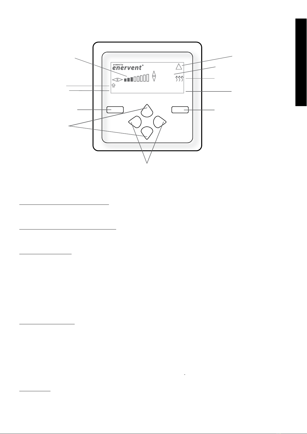
CONTROL PANEL BUTTONS
Buttons for quick adjustment of fan speed
Press the right arrow to increase fan speed.
Press the left arrow to decrease fan speed.
Buttons for quick adjustment of temperature
Press the up arrow to increase temperature.
Press the down arrow to decrease temperature.
Left multi-choice button
By pressing the left multi-choice button while the display is in its initial starting mode, you get to the list of ”quick
functions”. From the list you can choose which functions you immediately want to activate. The selection of functions
available on this list is made in Main Menu / Settings / Quick Choice.
The following quick choice functions are available:
- Overpressure or switch for the replace
- Boosting
- Maximum heating or cooling
- Night cooling allowed or prevented
Right multi-choice button
By pressing the right multi-choice button while the display is in its initial starting mode you get to the“Main Menu”. In the
Main Menu the following options are available:
- Reading and resetting an alarm.
- Setting time and date. NOTE! The year has to be set.
- Reading of measured temperature and humidity.
- Setting of time program at both week and year level.
- Inspection of the ventilation unit’s technical information.
- With a password you can go to the“Settings”menu (only for experts).
Keypad lock
The keypad lock is activated by pressing the left multi-choice button (Quick functions) and directly pressing the ”arrow
up” . You unlock in the same way.
+
+
-
-
Quick functions Menu
Status: Home
20°C
INFO row
Fan speed settings
Function
selected with
left multifunction button
Left multifunction
button
Buttons for quick
adjustment
of temperature
Buttons for quick
adjustment of
fan speed
Right multifunct
ion
button
Function
selected
with right multifunction button
Function symbol
T
emperature settings
!
Alarm
USER GUIDE

12
USER GUIDE
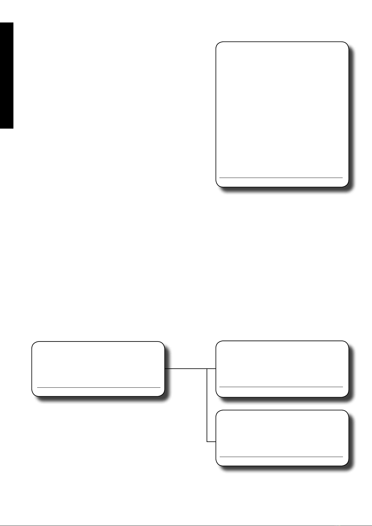
DISPLAY
Setting the fan speed
Fan speed settings on direct current models
(unit with direct current fans)
Coloured bars on the display show which ventilation eect is active:
1 = 20 - 29 %, 2 = 30 - 39 %, 3 = 40 - 49 %, 4 = 50 - 59 %, 5 = 60 - 69 %, 6 = 70 - 79 %, 7 = 80 - 89 %, 8 = 90 - 100 %. The exact
valueisshownonthedisplay,withanaccuracyofonepercent,forashortwhilewhenthebuttons+and-forfanspeed
adjustment are pressed. The ventilation eect which is active is shown under boosting, if the fans are in boost mode, oth-
erwise the initial setting is show. If a dierence in the fans’speeds has been set in the “settings”menu, then the number of
bars on the display is reduced depending on the dierence in speed. If a speed dierence has not been set, the maximum
number of bars is eight.
Example:
The extract air fan’s normal speed is 50 % and the supply air fan’s normal speed is 40 %. The dierence in speed is 1, so on
the display are shown 8 - 1 = 7 bars.
Temperature Settings
The chosen temperature setting is shown in numbers. It is the extract air temperature or the room temperature if a room
temperature sensor has been installed.
Function symbols
The symbol is showing which temperature control is active
The unit is cooling.
The unit is only using heat recovery to heat up / cool down the supply air.
The unit is heating.
20°C
V
V
V
V
V
V
V
V
!
Status: Home
INFO row
This row shows which mode the ventilation unit is in. The unit can be in one of the following statuses:
Home / Away / Long away / Boosting (°C or %RH or CO2) / Overpressure / Max heat or cooling / Stove / Ce Va Cl / Night
cooling
Service and alarm messages
The symbol for Service and alarm messages appears on the display if some error occurs with the unit or if the unit is in
need of service.

13
Enervent EDA MD EN 2013_1
USER GUIDE
CONTROL OVERVIEW
To get to the main menu of the control panel, press the right multi-choice button. In the menu, you navigate by using the
up or down arrow. When you are in the menu the function alternatives, which are: ”Exit”; ”Reset”; ”Choose” and ”Change”,
are shown on the bottom edge of the display. You can select these options by pressing the multi-choice button on the
corresponding side.
MENU STRUCTURE
Main menu:
Timeprograms
Measurements
Settings
Info
Alarm
Date and time
Year timer
Week timer
Temperatures
Situation controls
Boosting functions
Display settings
Quick choise
Other settings
Night cooling
Fan speed
page 16
page 15
page 16
page 16 Stove+CeVaCl+Overpr
Over pressure
page 17
Normal spd
CO2
Boosting settings
Humidity
page 18
page 16
Temp. boost
Away
HRC
Long away
page 20
page 23
page 24
page 23
page 19
page 19
page 19
page 19
page 21
page 22
page 22
page 21
page 22
page 23
page 23
page 23
page 23
page 14 END USER
VENTILATION ENGINEER
MANUFACTURER
XXX (=General settings) page 23
YYY (Standard duct pressure) page 19

14
USER GUIDE
MAIN MENU
ALARM
All alarm and service messages are visible in the unit’s Alarm menu. 20 alarms are shown in the list. An alarm can have one
of the following three statuses; ON, RES reset, but still active or OFF.
The alarms are divided into three classes, class A, class AB and class B. Class A alarms shut down the unit. Class AB-alarms set
the unit in failsafe mode. In failsafe mode the extract air fan runs on smallest eciency and the supply air fan stands still1.
Class B alarms do not aect the unit’s function. An alarm symbol is ashing in the display when class A and class AB alarms
are active. The light is not shown at class B alarms.
The unit doesn’t start before a class A alarm has been reset. Class AB-alarms reset automatically and the unit automatically
starts when the alarm no longer is valid.
For example TE30 min. alarm: If the extract air temperature has dropped below the set value for more than 10 min an alarm
i activated (ON) and the units goes into failsafe mode (AB-alarm). If the alarm is reset the alarm changes to RES mode, but
the failsafe situation continues. The unit does not start before the temperature rises over the set value and the alarm goes
into OFF mode.
There are two relay outputs for alarms on the EDA motherboard: ALM A and ALM B. Output ALM A conducts when a class
A alarm is active. Output ALM B conducts when an A- or AB-alarm is active and the time is within the alarm B output vali-
dity. The alarm B output can conduct weekdays between 9 am and 10 pm.
1 In passive house models also the extract air fan stops.
Main menu
Alarm
Measurements
Time programs
Info
Settings
Exit Choose
Alarm 1-20/20
Alarm name space
Alarm time DD:MM:YY HH:MM
Alarm text
Exit Reset

15
Enervent EDA MD EN 2013_1
USER GUIDE
DATE AND TIME
Setting up time, month and year. Weekday displayed automatically.
List of alarms
Alarm name Class Explanatory text row -- Alarm
limit
Delay NOTE!
TE5 min AB or B After HRC
supply air cold
+5°C 10 min Unit in failsafe mode.
TE10 min AB Supply air cold +10°C 10 min Unit in failsafe mode.
TE10 max A Fire risk supply temp high +55°C 2 sec Unit starts only after reset.
TE20 max A Fire risk room temp high +55°C 10 sec Highest measured room temperature is
higher than the set value. Unit starts only
after reset.
TE45 min A Watercoolerfreezerisk +8°C 2 sec Only EDW-units. Unit starts only after
reset.
TE30 min AB or B Extract air cold +15°C 10 min Unit in failsafe mode.
TE30 max A Fire risk extract temp high +55°C 2 sec Unit starts only after reset.
ELH-problem A Electrical coil overheating 2 sec Alarm information from ELH power to
input DI10. Unit starts only after reset.
Freezepro-
blem
BFreezeprobleminfo 2 sec Only Cooler-units.
E-stop A External emergency stop 0 sec The loop is connected to input DI1 (clo-
sing)
Fire risk A External 0 sec The loop is connected to input DI2 (clo-
sing)
Service
reminder
B 6
mnths
PDS10 B Pressure switch 2 sec Use of electrical heater is prohibited until
pressure dierence recovered.
SF A Deviation alarm 10 Pa 200 s Standard duct pressure control, the de-
viation for the alarm can be set
EF A Deviation alarm 10 Pa 200 s Standard duct pressure control, the de-
viation for the alarm can be set
Date and time
Time: 08:00
Day: 01 Thursday
Month: 1
Year: 2011
Exit Change
16
USER GUIDE
MEASUREMENTS
The Measurements menu is an informative menu where you can
read the dierent measurement results. Also measurements from
extra equipment like CO2and RH% sensors can be read here.
Explanations of the measurements:
Fresh air Outside air temperature
HRC sply Supply air temperature after the heat recovery
Sply Supply air temperature
Exhst Extract air temperature
Exhst water Return water temperature (EDW models)
NA No sensor connected
Exhaustair Exhaust air temperature
Room t. OP Room temperature, control panel measure result*
Exhst humidity Extract air humidity level
48 h humidity The average extract air humidity level during the
last 48 hours
HRC ŋ sply Supply air heat recovery rate
HRC ŋ exhst Extract air heat recovery rate
HRC -100...0 the unit is asking for cooling
0...+100(only)heatrecoveryinuse
+100...+200theunitisaskingforheating
+200...+300theunitisaskingforheatingofthe
additional heating unit (only EDX-E)
RH_1 Measurement of separate humidity sensor*
RH_2 Measurement of separate humidity sensor*
CO2_1 Measurement of carbon dioxide sensor*
CO2_2 Measurement of carbon dioxide sensor*
* sensor extra equipment
TIME PROGRAMS
In the Timeprogram menu you program the week and year
timers. For the week timer there are 20 program slots in which
yousetupwhentheprogramison(hh:mm–hh:mm+day)and
what function the unit is to perform during the time program.
For the year timer there are 5 program slots in which you set
up the time programs on and o time (dd.mm.yyyy, hh:mm) and
what function the unit is to perform during the time program.
Measurements
Fresh air xx,x°C
HRC sply xx,x°C
Sply xx,x°C
Exhst xx,x°C
Exhst. water /NA xx,x°C
Exhaustair
xx,x°C
Room t. OP xx,x°C
Exhst humidity xx %
48 h humidity xx %
HRC ŋ sply xx %
HRC ŋ exhst xx %
(HRC)
RH_1 xx %
RH_2 xx %
CO2_1 xx ppm
CO2_2 xx ppm
Exit
Time programs
Week timer
Year timer
Exit Choose
Week timer
Timeprogram: 1
On : 00:00 - 00:00
Su Mo Tu We Th Fr Sa
Function: Choose here
Exit Change
Year timer
Timeprogram: 1
Start: dd.mm.yyyy 00:00
End: dd.mm.yyyy 00:00
Function: Choose
Exit Change
If the end time for the time program is smaller than the start time,
the control interprets that the time program continues over the
day limit. In this case the next day also needs to be an allowed day. Example: Start: 16:00, End: 08:00, Allowed days: Mo, Tu,
We. This time programming means that the program start on Monday at 16:00, ends on Tuesday at 08:00, starts again on
Tuesday at 16:00 and ends on Wednesday at 08:00. After that the program is active again next Monday at 16:00.

17
Enervent EDA MD EN 2013_1
USER GUIDE
INFO
Informative menu that displays the unit’s technical details and program versions.
Info
Enervent
Pingvin eco EDE
Mother v. 2.11
Display v.. 2.01
SN 60387
Exit
Time program events:
Ventilation eect (1-8) for ventilation units with alternating current fans. The number of available ventilation eects
depend on the fan eect’s initial settings. If the speed of the supply air and extract air fan is the same, the number of avai-
lable eects are 8. If the dierence in speed is of 1, then the available number of eects are 7, if the dierence is of 3, then
the number is 5 etc.
Ventilation eect (20-100%) for ventilation units with eco direct current fans. The maximum available ventilation ef-
fect depends on the fan eect’s initial settings. If the speed of the supply air and extract air fan is the same, the maximum
eect available is 100%. If the dierence in speed is 10% then the available eect is 90% etc.
Away: The unit is set to the Away state.
Long away: The unit is set to the Long away state.
Max heat: Maximum heat is turned on. Event continues until the timer runs out or the limit value is reached.
Max cooling: Maximum cooling is turned on. Functions in the same way as max heat.
No heating: heating prohibited.
No cooling: Cooling prohibited.
Temp. drop: The temperatures set point is lowered according to the amount set in settings.
Timerly: Timed relay (DO2) is connected to activate at set time.

18
USER GUIDE
SETTINGS
In this menu, you enter the settings needed for taking the unit into use. The code is 6143.
Settings:
USER GUIDE
Temperatures
Situation controls
Boosting functions
Display settings
Quick choise
Other settings
Night cooling
Fan speed
Stove+CeVaCl+Overpr
Over pressure
Normal spd
CO2
Boosting settings
Humidity
Temp. boost
Away
HRC
Long away
page 20
page 23
page 24
page 24
page 19
page 19
page 19
page 19
page 22
page 22
page 21
page 22
page 3
page 23
page 23
XXX (=General settings) page 24
YYY (Standard duct pressure) page 19
page 21
page 23

19
Enervent EDA MD EN 2013_1
USER GUIDE
FAN SPEED
Fan speed
Normal spd.
Over pressure
Stove+CeVaCl+Overpr
YYY (=Constant duct pressure)
Exit Choose
Normal spd.
Supply fan #
Extract fan #
Ulkol. max: ##°C
Ulkol. min: ## °C
Back Change
Over pressure
Supply fan #
Extract fan #
OP t: # min
Exit Change
The dierence in speed between the supply air and extract air fan
is set in the normal speed menu. The set values do not dene
the fan speeds, just the dierence between them. The set values
aect the fan speed columns in the EDA control panel basic view
- the number of columns decline with the quantity of dierence.
For more information see the chapter about display symbols on
page 10.
The fan speed, during overpressure, is selected so that there is
enough natural draft in the chimney while lighting a re in the
replace. 10 – 15 minutes is usually enough.
Stove+CeVaCl+Overpr
CH CVC COC OCC
Sply # # # #
Exhst # # # #
Exit Change
Speeds for supply air and extract air fans can be set separately
for dierent combinations of the cooker hood, central vacuum
cleaner and the overpressure function.
CH = Cooker hood on, examples of fan speeds; extract 3 (or
30 %) and supply 5 (or 50 %).
CVC = Central vacuum cleaner on, examples of fan speeds;
extract 3 (or 30 %) and supply 5 (or 50 %).
COC = Cooker hood and central vacuum cleaner/over-pressure
and cooker hood/central vacuum cleaner and over pres-
sure on at the same time, examples of fan speeds; ex-
haust 3 (or 30 %) and supply 7 (70 %).
OCC = Overpressure, cooker hood and central vacuum cleaner
all on at the same time, examples of fan speeds; extract
3 (or 30 %) and supply 7 (or 80 %).
YYY (=Constant duct pressure)
Const. ductpr. □
CDPC EC P-a: ## Pa
CDPC EC I-t: ## s
CDPC EC R-t: ## s
CDPCECDz: ##Pa
CDPC AC Delay: ## s
CDPCACDz: ##Pa
??? ## Pa
??? ## Pa
??? Max: ## Pa
??? Min: ## Pa
??? Max: ## Pa
??? Min: ## Pa
TV: ## s
PV: ## s
???: ## Pa
Back Change

20
USER GUIDE
TEMPERATURES
Temp. settings
Exhst msrmnt ##,#°C
Sply msrmnt: ##,#°C
Temp ctrl mde From
Setpoint: ##,#°C
Min: ##,#°C
Max: ##,#°C
OP 1 □
OP 2 □
OP 3 □
OP 4 □
OP 5 □
Temp. trans 1 □
Temp. trans 2 □
Temp. trans 3 □
Exit Change
Extract msrmnts: Displays the extract air or room
temperature (depending on selected
temperature regulation) with one
decimal accuracy.
Supply msrmnts: Displays the supply air temperature
with one decimal accurancy.
Temp ctrl mode: Selection of temperature regulation.
Options are constant extract air regu-
lation or constant room temperature
regulation.
Setpoint: Selection of extract air or room
temperature setpoint with 1/10 de-
gree accuracy. Fast setup with one
degreeaccuracywith+and-onthe
control panel.
Min: Set lowest allowed supply air tempera-
ture.
Max: Set highest allowed supply air tempe-
rature.
OP1-OP5: Selection of control panels that partici-
pate in room temperature regulation.
If several panels are selected the room
temperature is shown as an average
value of the selected panels’measure
ments. One panel is included in the
standard delivery.
Temp.trans 1-3: Selection of temperature sensor (extra
equipment) that participate in room
temperature regulation. If several
panels are selected the temperature
is shown as an average value of the
selected panels measurements.
This manual suits for next models
13
Table of contents
Other ensto Fan manuals


 owner's manual")


