ensto HJHP33.2402 User manual
INSTALLATION INSTRUCTION PEM1268ENG
2012-02
ENGLISH
HEAT SHRINK JOINTS H-CABLE VS H-CABLE
HJHP33.2402, HJHP33.2402C, HJHP33.2403, HJHP33.2403C

2/12 HJHP33.24 PEM1268ENG 2012-02
GENERAL INFORMATION
- Check that the kit is suitable for the cable type.
- Check the materials listed in the bill of materials for completeness.
- Read the installation instructions carefully before starting the installation.
- Install carefully and make sure the materials are clean during the installation.
- Clean the working place after the installation.
GENERAL INSTRUCTIONS FOR HEAT SHRINKING
- Please note that in some working places a hot work permit is needed.
- Use a propane burner with a flame length of approx. 20-30 cm. Do not use too large or sharp flame.
- Move the flame all around the cable on the shrinking direction. Move the flame continuously to avoid over-
heating.
- Make sure that the ventilation is good and there are no flammable materials around.
- Clean the cable surfaces before shrinking.
- When shrinking, always follow the installation instructions and the relevant sequence to avoid trapped air.
- Check that the tube has shrunk evenly around the cable before you continue shrinking.
- If the tube turns around at the end of shrinking, straighten the tube by directing the flame inside the tube
from the opposite direction.
- After shrinking the tubes should be smooth and even following the shape inside.
LEGAL NOTICE
- The product must be installed only by a competent person with sufficient training in installation practices
and with sufficient knowledge of good safety and installation practices in respect of electrical equipment.
If local legislation contains provisions in respect of such training or sufficient knowledge in respect of
installation of electrical equipment such provisions shall be fulfilled by the said person.
- Ensto accepts no liability concerning claims resulting from misuse, incorrect installation or ignored na-
tional safety regulations or other national provisions.
- WARNING: Failure to follow the installation instructions may result in damage to the product and serious
or fatal injury.
PEM1268ENG 2012-02 HJHP33.24 3/12
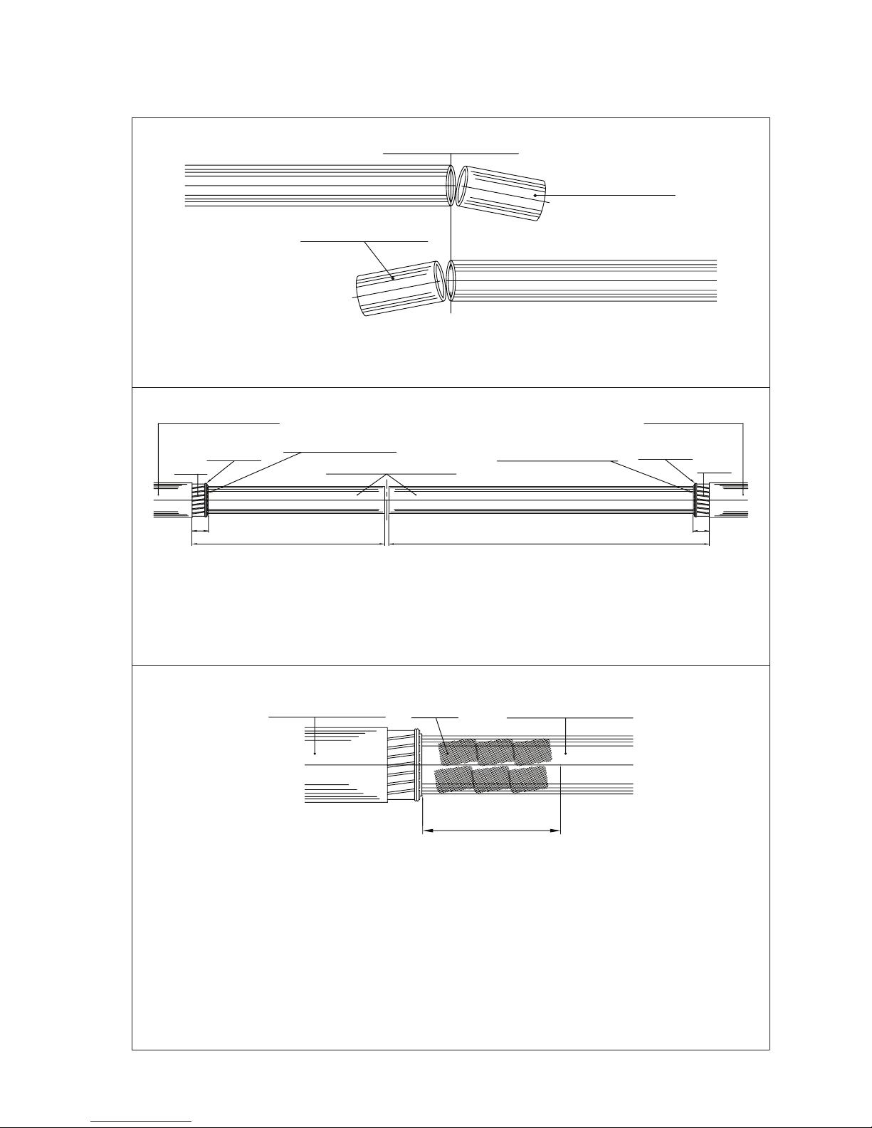
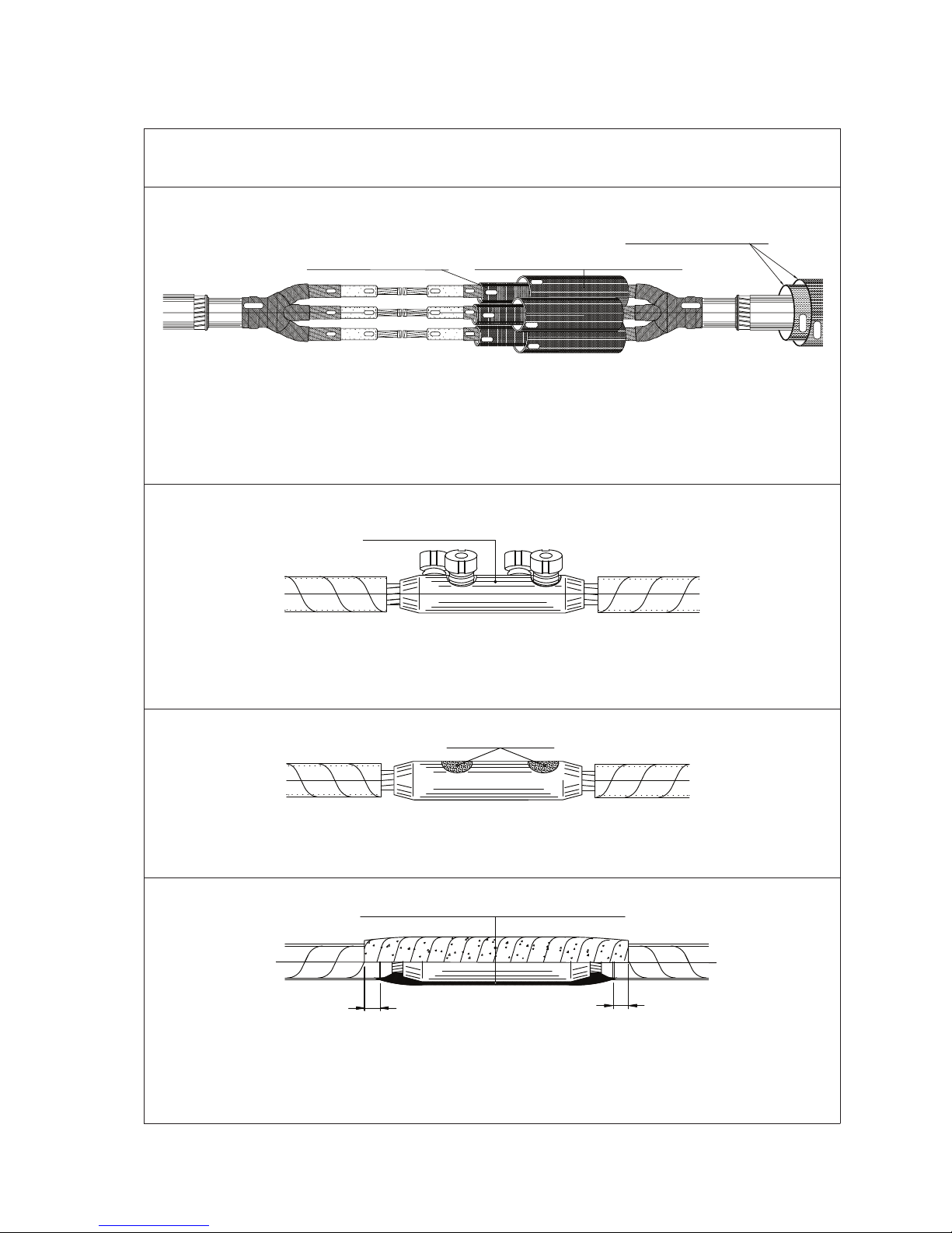
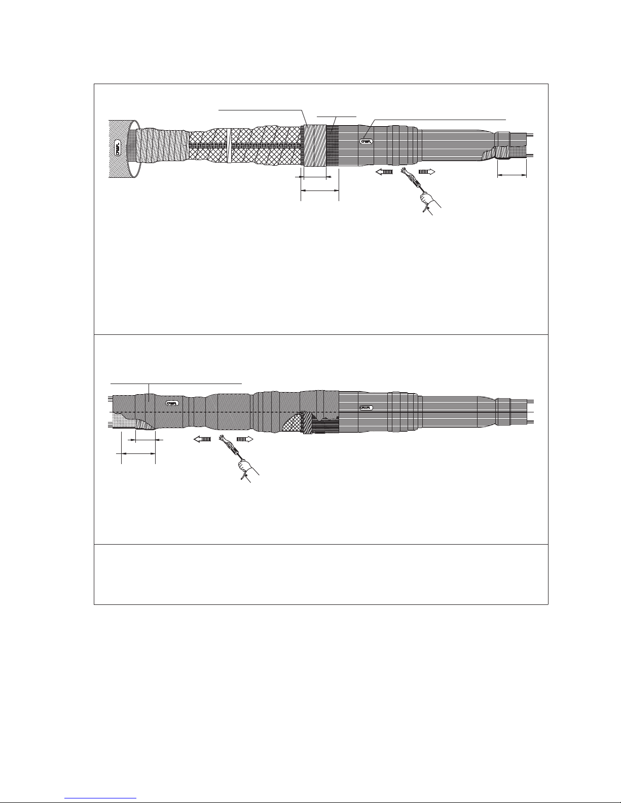
1. Overlap the cables for at least 300 mm. Cut the cables in the middle of the overlapping (reference
line).
2. Cut and remove the outer covering up to length of 700 mm from the cable with shorter peeling.
Other cables outer covering will be removed up to length 1250 mm. Cut and remove the armour-
ing up to 50 mm from the outer covering or sheath of both cables. Clean the armouring and fix it
with PVC tape. Cut and remove the possible inner covering or sheath.
3. Clean the outer covering up to at least 2 m distance avoiding inner side of outer tubes getting
dirty. Protect the outer covering for example with plastic sleeve. Roughen the armouring up to
length of 300 mm from armouring with grinding paper. Roughen the outer covering or sheath
around 75 mm. Clean the lead or aluminium sheath and the armouring.
Cut and remove the lead or aluminium sheath up to 300 mm from the outer sheath or up to
250 mm from the possible armouring. Cut and remove all the fillings.
Clean the remaining lead or aluminium sheath and the armouring with a suitable solvent. Clean
the phases carefully.
Reference line
Surplus part
Outer covering or sheath
Outer covering or sheath Roughen
Outer covering or sheath
PVC-tape PVC-tape
Inner covering or sheath Inner covering or sheath
Lead or aluminium sheath
Lead or aluminium sheath
250
Armouring Armouring
Surplus part
700
50 50
1250
4/12 HJHP33.24 PEM1268ENG 2012-02
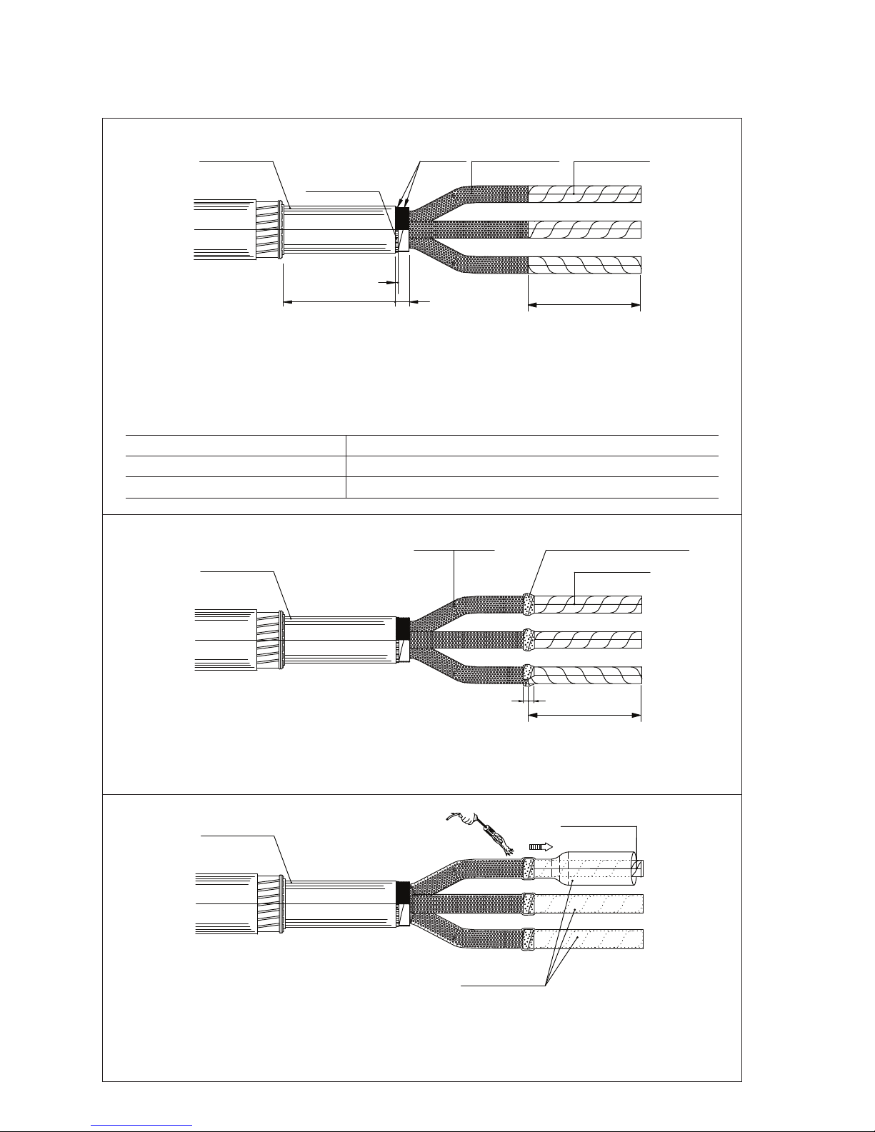
4. Fasten the cores for a length of 20 mm from the lead or aluminium sheath with the binding cord.
Spread the cores. Install the binding core up to length of 20 mm from amour. Remove the belt pa-
per insulation screen and outer layers of paper insulation up to length of B + 20 mm from the core
end. Clean the cores very carefully of extra oil. Clear the core ends about cutting pieces and dirt.
Table 1.
Kit B
HJHP33.2402, HJHP33.2402C 190 mm
HJHP33.2403, HJHP33.2403C 190 mm
5. Cover 10 mm of insulation shield and 10 mm of insulation starting from the insulation shield side.
The tape must be applied with 50 % overlap and by stretching it to half of its original width. Wrap
two layers of stress control tape SSCTA85 on the boundary of insulation shield and insulation.
STT
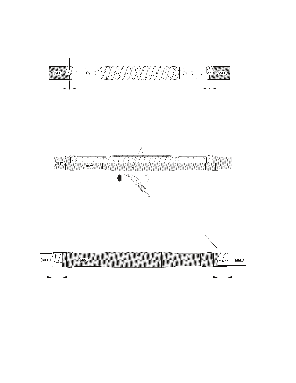
6. Place the transparent tubes (STT) on the cores down to 30 mm from the crutch (5 to 10 mm from
the binding core). Shrink the tubes one by one starting from the belt paper insulation end. Pay
extra attention to avoid air bubbles leaving under the tubes. Clear the transparent tubes after
cooling down.
Lead or aluminium sheath
Lead or aluminium sheath
Lead or aluminium sheath
Transparent tube
Semiconductive layer Stress control tape (SSCTA85)
Semiconductive
layer
Semiconductive
layer (5 mm)
Core insulation
Core insulation
Core insulation
B + 20
1010
250 20
5
B + 20
Binding
cord
PEM1268ENG 2012-02 HJHP33.24 5/12
SSET
SSET
SSET
150
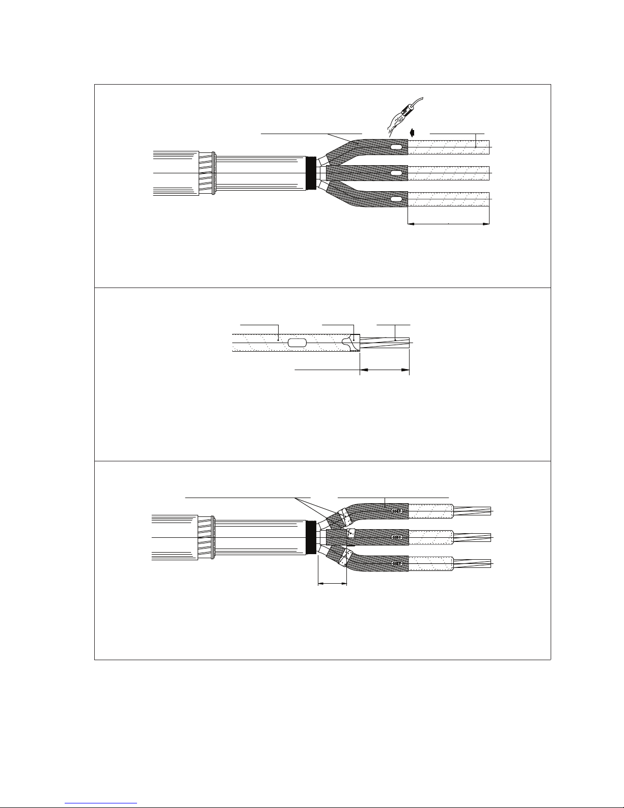
7. Place the semiconductive tubes (SSET) on the each core at the distance of B (Table 1) from the
conductor towards the crutch. Shrink each tube starting from the conductor end.
STT
8. Cut the transparent tubes and remove half of the bolt connector length + 5 mm from the insula-
tion of the cable. If you use compression connectors, remove the insulation following the con-
nector manufacturer’s instructions. Be careful not to nick the conductor when removing the last
paper layers. Clean the conductors and wrap some layers of PVC tape on them.
SSET
SSET
SSET
9. Wrap two layers of stress control tape SSCTA85 on the semiconductive SSET tubes. Cover 10 mm
of the tube starting at the distance 70 mm from the crutch. The tape must be applied with 50 %
overlap and by stretching it to half of its original width.
Semiconductive tubes (SSET)
Transparent tube
Stress control tape (SSCTA85) Semiconductive tube (SSET)
70
Half connector + 5
Conductor
Core
insulation
Conductor
B

6/12 HJHP33.24 PEM1268ENG 2012-02
SSET
SSET
SSET
10. Shape a piece of stress control tape SSCTA85 to at least 30 mm length according to the picture
and push it well into the crutch. The piece of the tape should fill up all the space in the crutch and
the between the adjacent cores. Push the cores together.
SSET
SSET
SSET
11. Wrap one layer of stress control tape SSCTA85 on the belt paper insulation starting from the lead
or aluminium sheath. Cover 20 mm of the lead or aluminium sheath and continue to cover 50 mm
of the cores. The tape must be applied with 50 % overlap and by stretching it to half of its original
width.
SSBO
SSET
SSET
SSET
12. Push the semiconductive breakout SSBO into the crutch as far as possible. Shrink the breakout
starting from the middle.
Stress control tape (SSCTA85)
30
Stress control tape (SSCTA85)
Stress control tape (SSCTA85)
20 50
Binding
cord
Belt
insulation
Semiconductive breakout SSBO
PEM1268ENG 2012-02 HJHP33.24 7/12
13. Repeat the steps 3 – 12 also to the other cable. Use longer transparent and semiconductive tubes.
SSBO
SSET
SSET
SSET
SIST
SISCT
SSET
SSET
SSET
SIST
SIST
SSBO
CPEEPL
CPEEPL
STT
STT
STT
STT
STT
STT
SISCT
SISCT
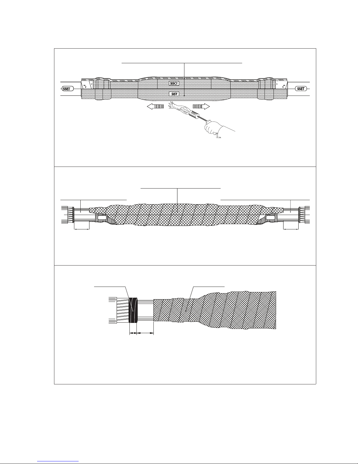
14. Slip the sealing tube(s) CPEEPL (or CPEEL) on cables. Protect them against dirt.
Slip the insulating / semiconductive tubes and the stress control tubes (SISCT and SIST) on each
core. Protect them against dirt.
15. Remove the PVC tape from the ends of the conductors and install the MV connectors following the
manufacturer’s instructions. Round the sharp angles. Please note that a sector shaped conductor
may need to be rounded to fit into the connector.
16. Fill any holes left in the connector with grey mastic. Clean the connector.
17. Fill the gap between the end of the connector and the insulation with stress control tape
(SSCTA85). Then wrap two layers of stress control tape (SSCTA85) to cover the connector covering
15 mm of the transparent tube on the both cables sides. Stress control tape (SSCTA85) must be
applied with a 50 % overlap and by stretching it to half of its original width.
Stress control tube (SISCT) Insulating and semiconductive tube (SIST)
MV connector
Gray mastic
Stress control tape (SSCTA85)
15 15
Sealing tube CPEEPL (CPEEL)
8/12 HJHP33.24 PEM1268ENG 2012-02
SSET STT SSET
STT
18. Wrap two layers of stress control tape SSCTA85 on the semiconducting tube (SSET) edge on both
cables. Start from the semiconductive layer side about 10 mm and cover 10 mm of transpar-
ent tube. SSCTA85 must be applied with a 50 % overlap and by stretching it to half of its original
width.
SISCT
SSET
19. Centre the stress control tube SISCT on the connector. Start shrinking the tube from the middle
and move towards the ends. Clean the surface of the stress control tube after shrinking.
SSET SISCT SSET
20. Wrap two layers of stress control tape SSCTA85 length of 30 mm on the semiconducting tube
starting from the end of the paper cable insulation. Start from the edge of the stress control tube
and cover 30 mm of the SSET tube. SSCTA85 must be applied with a 50 % overlap and by stretch-
ing it to half of its original width.
Stress control tape (SSCTA85)
10 10 10 10
Stress control tape (SSCTA85)
Stress control tube (SISCT)
Stress control mastic SSCTA85 Stress control mastic SSCTA85
Stress control tube (SISCT)
30 30
PEM1268ENG 2012-02 HJHP33.24 9/12
SSET
SISCT
SIST
SSET
21. Centre the insulating and semiconductive tube SIST on top of the stress control tube. Start
shrinking it from the middle and move towards the ends.
SSBO SSBO
22. Push the cores together and wrap them with tinned copper tape. Wrap tinned copper tape on the
core assembly leaving 120 mm of the lead or aluminium sheath uncovered. Tinned copper tape
must be applied with a 20 % overlap. Fix the end of the tape by knotting it.
23. Wrap PA22 mastic to cover 40 mm length of lead sheath or aluminium sheath on the side of outer
sheath. Leave some 80 mm of lead sheath or aluminium sheath uncovered.
Repeat the procedure on the other side of the joint.
Insulating and semiconductive tube (SIST)
Lead or aluminium sheath
Copper braid
Sealing mastic (PA22)
40 80
120 120
Lead or aluminium sheath
Tinned copper tape
10/12 HJHP33.24 PEM1268ENG 2012-02
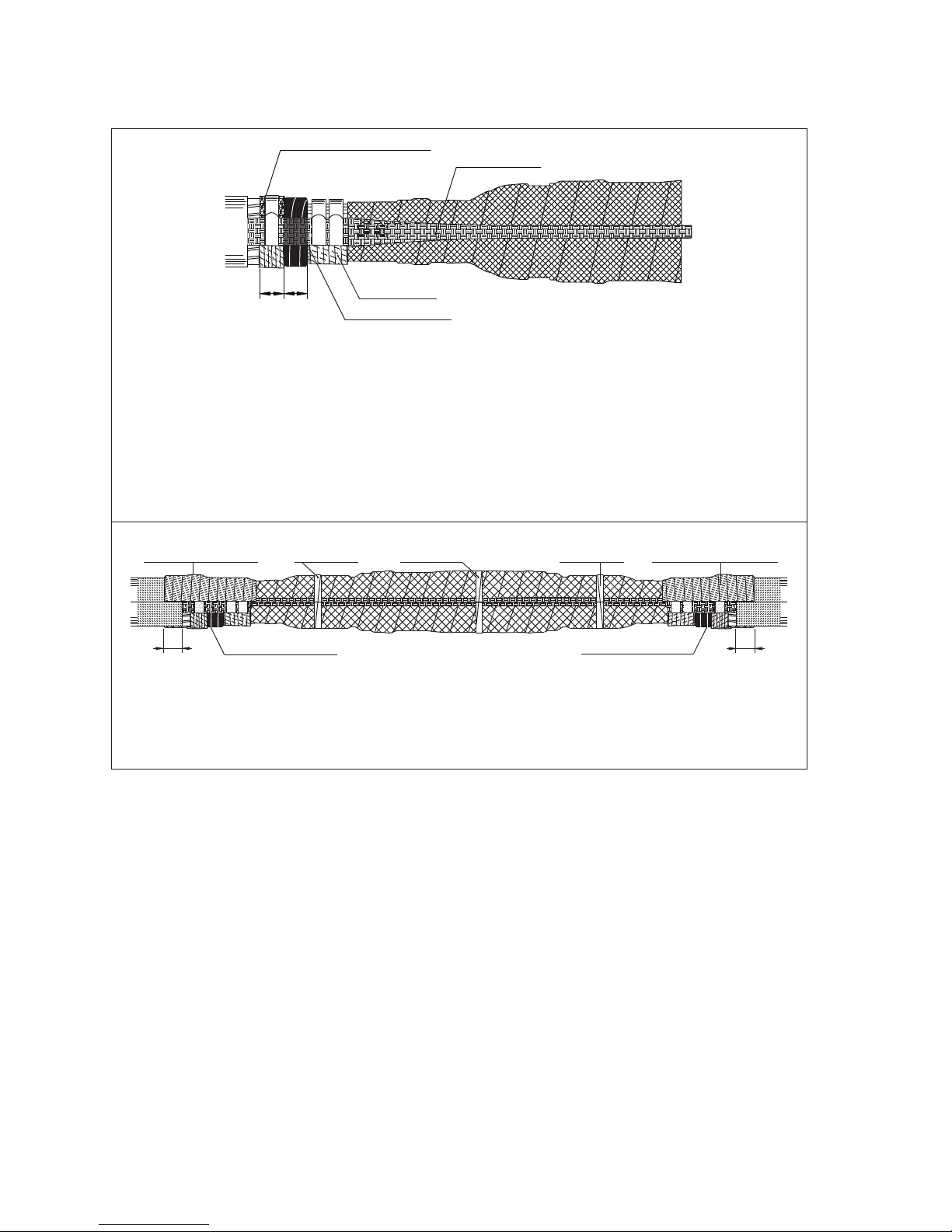
24. Wrap tinned copper tape over the armouring. Fix the copper tape to armouring by knotting it.
Set the two ground copper braids on the tinned copper tape on the lead or aluminium sheath
(on the opposite sides of cable joint) so that the braids ends are on the same line as interface of
outer sheath and armouring. Spread the end of copper braid and fix it on the possible armour with
constant force spring (1 pc / joint side). Fix the copper braid on lead sheath with constant force
springs (2 pcs / joint side). Tighten the constant force springs and wrap SSITA42 tape on them us-
ing 1 tape / 1 constant force spring. Wrapping direction should be chosen so that the springs will
get tightened.
25. Use some PVC tape to keep the braid on the joint. Wrap two layers of sealing mastic PA22 on the
both sides of joint so, that 50 mm of outer covering will be covered, armouring, lead sheath and
constant force spring areas will be covered as well.
PVC-tape PVC-tape PVC-tape
Sealing mastic (PA22)
Sealing mastic (PA22) Sealing mastic (PA22)
50 50
Sealing mastic (PA22)
Tinned copper tape (8 rounds)
Tinned copper braid
SSITA42 tape
Tinned zone
3030
PEM1268ENG 2012-02 HJHP33.24 11/12
26. Slide the smaller CPEEPL (or CPEEL) sealing tube so that it overlaps the previously roughened
75 mm of the cable. Start shrinking the tube from middle and move towards the ends. The tube is
properly shrunk when the adhesive starts to come out from the ends.
Roughen around 75 mm of the first shrunk tube on the end closer to the centre of the joint with
grinding paper. Wrap one layer of sealing mastic PA22 on the tube for 50 mm length in the outer
end of the roughened area.
CPEEPL
CPEEPL
27. Slide the bigger CPEEPL (or CPEEL) sealing tube so that it overlaps the previously roughened
75 mm of the first sealing tube. Start shrinking the tube from middle and move towards the ends.
The tube is properly shrunk when the adhesive starts to come out from the ends.
28. The joint is finished and ready to use, but let it cool down before loading it mechanically.
75
50
Sealing tube (CPEEPL or CPEEL)
Sealing mastic PA22
Sealing tube (CPEEPL or CPEEL)
50
75
75
Roughen

ENSTO FINLAND OY
ENSIO MIETTISEN KATU 2, P.O.BOX 77
06101 PORVOO, FINLAND
TEL. +358 204 76 21
FAX +358 204 762 770
WWW.ENSTO.COM
PEM1268ENG / Issue 2012-02-01
UTILITY NETWORKS
This manual suits for next models
3
Table of contents


