Entec Timberwolf TW 35DH User manual

TIMBER
TIMBERWOLF
WOLF
IINNSSTTRRUUCCTTIIOONN
MMAANNUUAALL
EENNTTEECC
IINNDDUUSSTTRRIIEESS
LLTTDD
EENNTTEECC
HHOOUUSSEE,,
TTOOMMOO
IINNDDUUSSTTRRIIAALL
EESSTTAATTEE,,
CCRREEEETTIINNGG
RROOAADD,,
SSTTOOWWMMAARRKKEETT,,
SSUUFFFFOOLLKK
IIPP1144
55AAYY
TTEELLEEPPHHOONNEE
0011444499
776655880000
FFAAXX
NNUUMMBBEERR
0011444499
776655880011
wwwwww..ttiimmbbeerrwwoollff-uukk..ccoomm
TW 35/150DH
TW 35/150DH

CONTENTS
Section Page No.
INTRODUCTION 1
PURPOSE OF MACHINE 2
MACHINE DIMENSIONS & SPECIFICATIONS 2
PARTS LOCATION DIAGRAMS 3 & 4
SAFE WORKING 5
Operator’s Personal Protective Equipment Required 5
Basic Woodchipping Safety 5
General Safety Matters - Do’s and Dont’s 6
Noise Test 7
OPERATING INSTRUCTIONS 8
Safe Transportation 8
Hitching onto the Tow Ball 8
Unhitching the Chipper 8
Delivery 9
Operator’s Personal Protective Equipment Required 9
Manual Controls 9
Auto Controls 10
Emergency Stopping 10
Engine Controls 10
Hydraulic Oil Thermometer 10
Hydraulic Oil Lever Indicator 10
Diesel Tank Indicator 10
Starting the Engine 11
Stopping the Engine 11
Daily Checks Before Starting 11
Before Using the Chipper 11
Starting to Chip 12
Chipping 12
Blockages 12
SERVICE INSTRUCTIONS 13
Service Schedule 13
Engine Servicing 14
Safe Maintenance 14
Spares 14
Battery Removal and Maintenance 14
Change Blades 15
Check Fittings 16
Check Hoses 16
Tension Drive Belt 16
Tension Hydraulic Pump Belts 16
Change Hydraulic Oil and Filter 17
Service to the Safety Bar 17
Grease the Roller Drive Splines 18
Grease the Roller Box Slides 18
Greasing Rotor Bearings 18
Engine Manufacturer’s Handbook 18
WARRANTY STATEMENT 19
IDENTIFICATION PLATES 20
PARTS LISTS 22 - 36
AMENDMENTS 38 - 41
ISSUE 21

TIMBERWOLF
Thank you for choosing this Entec/Timberwolf brushwood chipper. Entec/Timberwolf
chippers are designed to give safe and dependable service if operated according to the
instructions.
Before using your new chipper, please take time to
read this manual which contains
IMPORTANT HEALTH AND SAFETY INFORMATION
and explains the chipper controls - failure to do so could result in :
- personal injury
- equipment damage
- damage to property
- a member of the general public becoming injured
This manual covers the operation and maintenance of the Timberwolf TW 35/150DH.
All information in this manual is based on the latest product information available at the
time.
All the information you need to operate the machine safely and effectively is contained
within pages 3 to 12. Ensure that all operators are adequately trained for operating
this machine especially with regard to safe working practices.
Entec's policy of constantly improving their products may involve major or minor
changes to the chippers or their accessories. Entec Industries reserves the right to
make changes at any time without notice and without incurring any obligation.
Due to improvements in design and performance during production, in some cases
there may be minor discrepancies between the actual chipper and the text in this
manual.
The manual should be considered a permanent part of the
machine and should remain with it if the machine is resold.
!CAUTION or WARNING
Be aware of this symbol and where shown
carefully follow the instructions
This caution symbol indicates important safety messages in this manual. When
you see this symbol be alert to the possibility of injury to yourself or others, and
carefully read the message that follows.
Always follow safe operating and maintenance practices
INTRODUCTION
1
TW 35/150DH
Serial No. Location
The serial number can be
found on top of the rotor
housing.
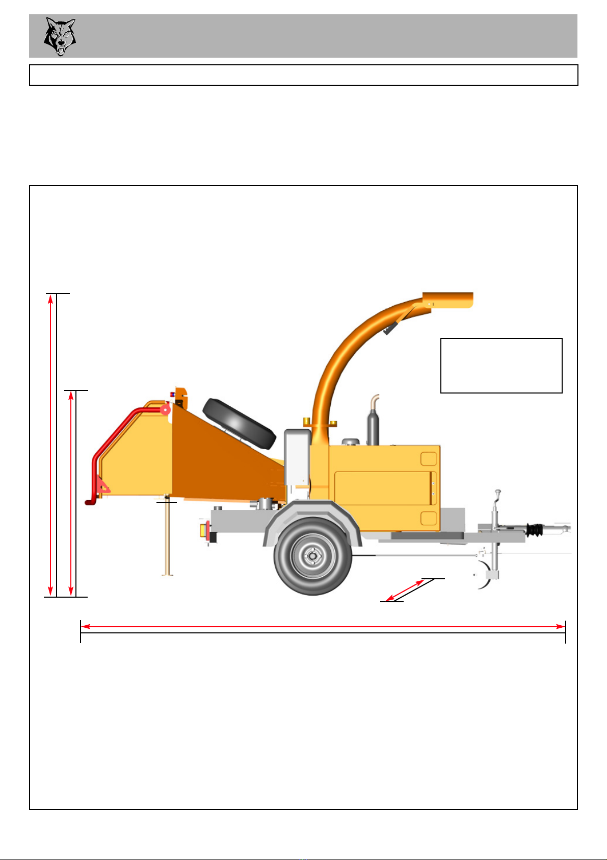
The Timberwolf TW 35/150DH brushwood chippers are designed to chip
solid wood material up to 150mm in diameter. The maximum cross-section
hardwood for continuous feed is 8500 sq. mm.They are capable of chipping
over 2.5 tonnes of brushwood per hour.
1400 mm
DIMENSIONS
2250 mm
3550 mm (3050 mm with feed table folded)
1400 mm
PURPOSE OF MACHINE
Engine Type Kubota 4 Cyl. Diesel
Maximum Power 26.1 KW (35 HP)
Cooling Method Water Cooled
Overall Weight 770 kilos
Starting Method Electric
Roller Feed Twin series hydraulic motors
Maximum Diameter Material 150mm (6")
Fuel Capacity 41 litres
Hydraulic Oil Capacity 13 litres
Material Processing Capacity 2.5 tonnes/hr
Fuel Type Diesel
Timberwolf TW 35/150DH Specification
fig 1.
TIMBERWOLF 2
TW 35/150DH
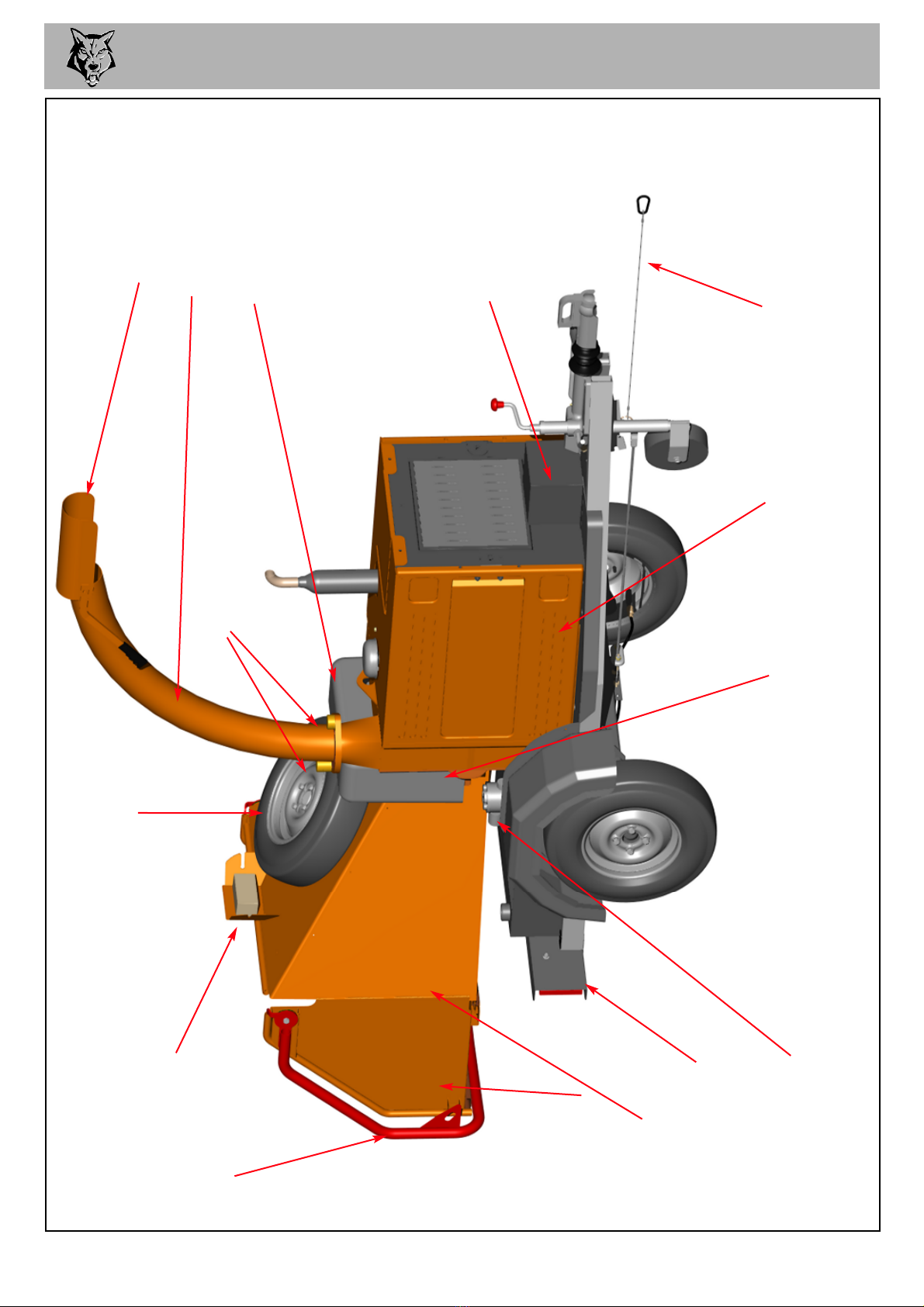
PARTS LOCATOR 3
CONTROL BAR
FEED TRAY
FUNNEL
DISCHARGE
BUCKET
DISCHARGE
TUBE
SPARE WHEEL
CLAMP NUTS
fig 2.
LIGHT BOARD
CONTROL BOX
BATTERY BOX
COVER
ROLLER
BOX COVER
SIDE PANELS
HYDRAULIC OIL
FILTER
ROTOR
HOUSING
BREAKAWAY
CABLE
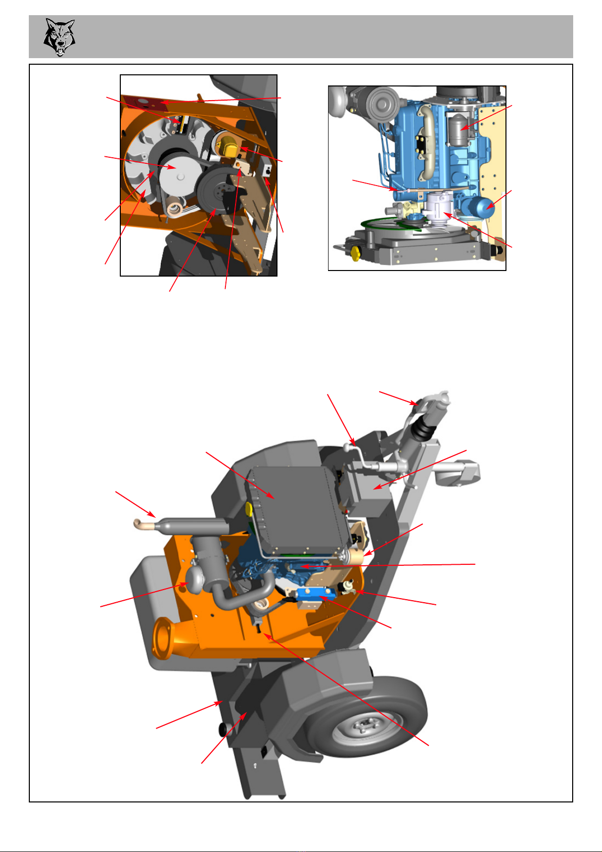
PARTS LOCATOR 4
fig 3.
JOCKEY WHEEL
ASSEMBLY
BATTERY
TOW HEAD
FUEL TANK
ENGINE
BLOCK
ROTOR
FAN
ROTOR
PULLEY
HYDRAULIC
PUMP
DRIVE
PULLEY
CUTTER
BLADE
TOOL BOX
BELT
TENSION
ADJUSTER
ELECTRIC
VALVE
FUEL PUMP
EXHAUST
FUEL
FILTER
NO STRESS
UNIT
NO
STRESS
SENSOR
DIP
STICK
OIL
FILTER
ALTERNATOR
CONTROL
PANEL
STARTER
MOTOR
RADIATOR
AIR FILTER

SAFE WORKING
OPERATOR'S PERSONAL PROTECTIVE EQUIPMENT REQUIRED
Chainsaw safety helmet fitted
with visor and recommended
ear defenders to the
appropriate specifications
Loose fit,
Heavy-duty gloves.
Close fitting heavy-duty
non-snag clothing
Face mask if
appropriate.
DO NOT wear rings,
bracelets, watches, jewellery
or any other items that could
be caught in the material and
draw you into the chipper.
BASIC WOODCHIPPING SAFETY
The operator should be aware of the following points:
MAINTAIN A SAFETY EXCLUSION ZONE around the chipper of at least 10 metres for the
general public or employees without adequate protection. - Use hazard tape to identify this
working area and keep it clear from debris build up. Chips should be ejected away from any
area the general public have access to.
HAZARDOUS MATERIAL. Some species of trees and bushes are poisonous. The chipping
action can produce vapour, spray and dust that can irritate the skin. This may lead to
respiratory problems or even cause serious poisoning. Check the material to be chipped before
you start. Avoid confined spaces and use a facemask if necessary.
BE AWARE when the chipper is processing material that is an awkward shape. The material
can move from side to side in the funnel with great force. If the material extends beyond the
funnel the brash may push you to one side causing danger. Badly twisted brash should be
trimmed before being chipped to avoid thrashing in the feed funnel.
BE AWARE that the chipper can eject chips out of the feed funnel with considerable force.
Always wear full head and face protection.
ALWAYS work on the side of the machine furthest from any local danger, e.g not road side.
WARNING
The Chipper will feed material through on its own. To do this, it relies on
sharp blades both on the feed rollers and the chipper rotor. To keep the
blades sharp, only feed the machine with clean brushwood.
DO NOT put muddy / dirty wood, roots, potted plants, bricks,
stones or metal into the chipper.
!
!
Safety Boots
5

SAFE WORKING 6
DO’S AND DONT’S
GENERAL SAFETY MATTERS
DO NOT use chipper unless available light is
sufficient to see clearly.
DO NOT use or attempt to start the chipper
without the feed funnel, belt guard, guards and
discharge unit securely in place.
DO NOT start the chipper running unless properly
guarded.
DO NOT stand directly in front of the feed funnel
when using the chipper. Stand to one side.
DO NOT allow -
DO NOT smoke when refuelling.
Petrol is explosive!
DO NOT let anyone who has not received
instruction operate the machine.
DO NOT climb on the machine at any time.
DO NOT handle material that is partially engaged
in the machine.
DO NOT touch any exposed wiring whilst
machine is running.
- to enter the machine, as damage is likely.
BRICKS STRING CLOTH PLASTIC STONES
METAL GLASS RUBBER ROOTS BEDDING
PLANTS
ALWAYS stop the chipper engine before making
any adjustments, refuelling, or cleaning.
ALWAYS check machine has stopped rotating
and remove chipper ignition key before
maintenance of any kind, or whenever the
machine is to be left unattended.
ALWAYS check machine is well supported and
cannot move.
ALWAYS run with the engine set to maximum
speed.
ALWAYS check (visually) for fluid leaks.
ALWAYS take regular breaks. Wearing personal
protective equipment for long periods can be
tiring and hot.
ALWAYS keep hands, feet and clothing out of
feed opening, discharge and moving parts.
ALWAYS use the next piece of material or a push
stick to push in short pieces. Under no
circumstances should you reach into the funnel.
ALWAYS keep the operating area clear of people,
animals and children.
ALWAYS keep the operating area clear from
debris build up.
ALWAYS keep clear of the chip discharge tube.
Foreign objects may be ejected with great force.
ALWAYS ensure protective guarding is in place
before commencing work. Failure to do so may
result in personal injury or loss of life.
ALWAYS use chipper in a well ventilated area -
exhaust fumes are dangerous.
!

SAFE WORKING
MACHINE:
NOTES:
TW 35/150DH
Tested Chipping 120mm x 120mm Corsican Pine
1.5m in length
113.2 dB 97.7 dB
1 METRE
96.5 dB
95.3 dB
94.0 dB
R= 4 metres
Noise levels between 90 and 114dBA will be experienced at the working position. Wear ear
defenders at all times to prevent possible damage to hearing. All persons within a 4 metre
radius must also wear good quality ear defenders.
NOISE TEST
7
fig 4.
Guaranteed Sound Power: 121db

OPERATING INSTRUCTIONS 8
SAFE TRANSPORTATION
WHEN towing a chipper the maximum speed limit is 60 mph.
ON rough or bumpy road surfaces reduce speed accordingly to protect your machine from
unnecessary vibration.
WHEN towing off road be aware of objects that may catch the chipper undergear.
WHEN towing off road ensure inclination is not excessive.
AVOID excessively pot holed ground.
WHEN reversing the chipper the short wheel base will react quickly to steering.
ALWAYS check the discharge is tight before moving.
KEEP tyre pressures inflated to 2.2 bar or 32 psi.
CHECK wheel nuts are tightened to 90Nm or 65 lbs ft.
CLEAR loose chippings and debris from the machine before departing.
ENSURE the feed funnel is closed and the catch is properly engaged before departing.
CHECK the ball head is well greased.
WIND jockey wheel assembly anticlockwise until the tow head is above the height of the ball
hitch on the vehicle.
REVERSE the vehicle so the ball hitch is directly below the tow head.
ATTACH the breakaway cable to a strong point on the vehicle, not the ball hitch.
ENSURE the barrel lock is retracted from the tow head.
GRASP handle on tow head and push back catch with thumb.
WIND the jockey wheel assembly clockwise, so lowering the tow head onto the ball hitch.
RELEASE handle and continue to wind jockey wheel clockwise. The tow head should snap
into place on the ball hitch. If it doesn't repeat previous 2 steps.
WIND jockey wheel up until fully retracted and the jockey wheel frame is seated in its notch on
the stem. The chipper weight should be fully on the vehicle.
RELEASE the jockey wheel clamp and slide the jockey wheel assembly fully up.
TIGHTEN clamp on the jockey wheel assembly.
CONNECT electrical plug to socket on rear of towing vehicle and check operation of all the
trailer and vehicle lights.
INSERT the barrel lock for security.
THE chipper is now properly attached to the vehicle.
HITCHING ONTO THE TOW BALL
ENSURE the chipper will not roll away after being disconnected from the vehicle.
DISCONNECT the electrical cable from the vehicle socket.
RELEASE the barrel lock.
RELEASE breakaway cable.
RELEASE the jockey wheel assembly clamp.
LOWER the jockey wheel assembly fully.
RETIGHTEN the jockey wheel assembly clamp.
WIND the jockey wheel assembly anticlockwise until it starts to take the weight of the chipper.
GRASP the handle and release the catch with your thumb.
CONTINUE to wind the jockey wheel anticlockwise. This should lift the tow head clear of the ball hitch.
DRIVE the vehicle clear of the chipper.
WIND the jockey wheel assembly to a suitable point where the chipper is level.
THE chipper is now fully detached from the vehicle.
UNHITCHING THE CHIPPER

OPERATING INSTRUCTIONS 9
DELIVERY
All Timberwolf 35/150DH machines have a full pre - delivery inspection before leaving the factory and
are ready to use. Read and understand this instruction manual before attempting to operate the
Chipper. In particular, read pages 5-7 which contain important health and safety information and
advice.
OPERATOR’S PERSONAL PROTECTIVE EQUIPMENT REQUIRED
CHAINSAW safety helmet fitted with visor and
recommended ear defenders to an appropriate
specification.
HEAVY-DUTY gloves.
CLOSE - FITTING heavy-duty non-snag clothing.
SAFETY footwear.
FACE MASK (if appropriate).
MANUAL CONTROLS
Do not rely on the red bar to keep the rollers stationary if it
is necessary to clear or touch the rollers. Always switch off
the machine before approaching the rollers.
GREEN FORWARD
FEED BUTTON
BLUE REVERSE
FEED BUTTON
RED STOP FEED -
EMERGENCY STOP
BUTTON
RED SAFETY BAR
Control Panel Diagram
fig 5.
Roller control box - is the control box above the feed opening of the chipper funnel. Its function is to control
the feed rollers. The feed rollers draw material into the machine. It does not control the main rotor.
RED SAFETY BAR = This is the large red bar that surrounds the feed tray and side of the feed funnel.
The bar is spring loaded and connected to a switch that will interrupt the power to the rollers. The
switch is designed so that it only activates if the bar is pushed to the limit of its travel. The rollers stop
instantly, but can be made to turn again by pressing either the GREEN FEED or BLUE REVERSE
control buttons.
RED SAFETY BAR TEST
To ensure the safety bar is always operational it must be activated once before each work session.
The rollers will not function until the bar is activated. This procedure must be repeated each time
the ignition is switched off.
GREEN BUTTON = forward feed - Push the button once - this activates the rollers and will allow you
to start chipping (if the rotor speed is high enough).
RED BUTTON = stop feed / emergency stop - This button stops the rollers from feeding. It overrides
all other buttons or bars and will not allow the other buttons to function until it has been reset.
To reset, twist until it returns to its original position. The forward and reverse buttons will now function.
BLUE BUTTON = reverse feed - allows you to back material out of the rollers. The rollers will only
turn in reverse as long as you keep pressing the button. You do not have to press the STOP button
before pressing the GREEN FEED button to recommence feeding.
See page 5 for more detailed information.
OPERATING INSTRUCTIONS 10
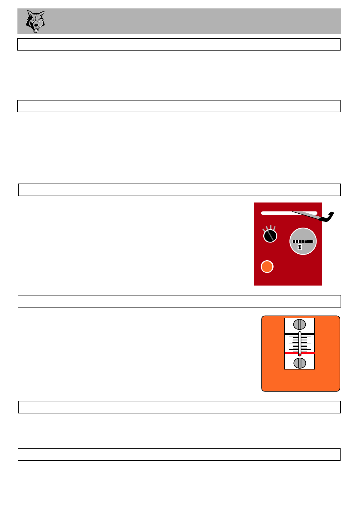
ENGINE CONTROLS
The engine speed is controlled by the horizontally adjustable
lever shown in the drawing. With the throttle lever in the FAST
position the machine is ready to chip. It MUST be fully
pushed to the left to achieve a suitable working speed.
If no wood is to be chipped for a few minutes the throttle
should be returned to the idle position.
fig 6.
AUTO CONTROLS
The no stress unit controls the feed rate of the material going into the chipping chamber. If the engine
speed is below the predetermined level the No Stress Unit will not allow the feed rollers to work in
either forward or reverse until the rotor speed rises above the predetermined level, at which point the
feed rollers will start turning without warning.
Push the RED STOP button or push the RED CONTROL BAR
(whichever is the quickest for you to reach).
Turn off the engine ignition key.
The emergency stop will prevent any more material being fed into the chipper. The rotor will still be
turning. The engine must be powered down to stop the rotor.
EMERGENCY STOPPING
This is situated on the side of the hydraulic oil tank. When the chipper is
running the oil temperature should not exceed 65oC. If it does, stop the
machine immediately. Failure to do so may result in damage.
Overheating can result from the chipper being worked extremely hard in
hot conditions, as the oil is not getting a chance to cool down. Stop the
chipper and allow oil to cool before continuing. If the temperature goes
above 65oC and the machine is not being worked hard or the air
temperature is not particularly hot this indicates low oil, a stuck hydraulic motor
or valve. Stop immediately and investigate.
HYDRAULIC OIL THERMOMETER
HYDRAULIC OIL LEVEL INDICATOR
When the chipper is on level ground the oil level should sit between the red line at the bottom of the
gauge and the black line at the top. If this level drops significantly it indicates an oil leak. Stop
immediately and investigate.
LA
fig 7.
FUEL LEVEL INDICATOR
This is located inside the tank. Remove the filler cap and look inside. A graduated plate helps to
judge the remaining fuel.
FAST SLOW
HEATERS ON
OFF START
HOURS
0000000

OPERATING INSTRUCTIONS 11
STARTING THE ENGINE
FOR COLD STARTING
Insert the key into the ignition switch.
Turn the key to the 'heat' position.
Hold it for 15 seconds.
Turn to the start position until the
engine fires.
Release the key and let it return to
the ignition position.
FOR WARM STARTING
Insert the key into the ignition switch.
Turn it to the 'heat' position.
Hold it for 5 seconds.
Turn to the start position until the
engine fires.
Release the key and let it return to
the ignition position.
LOCATE the machine on firm level ground.
CHECK machine is well supported and
cannot move.
CHECK prop stand is lowered and secure.
CHECK all guards are fitted and secure.
CHECK the discharge unit is in place and
fastened securely.
CHECK discharge tube is pointing in a safe
direction.
CHECK the feed funnel to ensure no objects
are inside.
CHECK feed table is in up position - to
prevent people reaching rollers.
CHECK controls as described below.
CHECK (visually) for fluid leaks.
CHECK fuel and hydraulic oil levels.
For parts location see diagrams on pages 3 & 4.
STOPPING THE ENGINE
Reduce the throttle to idle.
Leave the engine to run for a full minute.
Switch the key to the OFF position.
Remove the ignition key.
For more detailed information refer to the
Engine Owner’s Manual
BEFORE USING THE CHIPPER
IT IS ESSENTIAL TO CARRY OUT THE FOLLOWING TESTS to check safety equipment - this sequence
of tests will only take a few seconds to carry out. We recommend that these tests are carried out daily.
Observing the function as described will confirm that the safety circuits are working correctly. This is also a
good opportunity to remind all operators of the control and emergency stop systems.
4
7
568
23
PRESS THE GREEN
BUTTON
THE ROLLERS
SHOULD RUN
PRESS THE RED BAR
THE ROLLERS SHOULD
STOP
PRESS THE BLUE BUTTON
THE ROLLERS SHOULD TURN
BACKWARDS ONLY WHILE THE
BUTTON IS PRESSED
PRESS THE GREEN
BUTTON AGAIN
THE ROLLERS SHOULD
RUN
PRESS THE EMERGENCY
RED BUTTON
THE ROLLERS SHOULD
STOP
PRESS THE BLUE
BUTTON
THE ROLLERS
SHOULD NOT TURN
TWIST TO RESET
THE RED BUTTON
THE MACHINE IS READY
TO USE
1
PRESS THE RED
BAR TO POWER
THE CONTROL
SYSTEM
DAILY CHECKS BEFORE STARTING
OFF
IGNITION START
HEAT
fig 8.
If the engine fails to start after 10 seconds leave for 1 minute and try again.
WITH THE ENGINE RUNNING AT FULL SPEED

OPERATING INSTRUCTIONS
STARTING TO CHIP
WARNING
Do not use or attempt to start the chipper without the
protective guarding and discharge unit securely in place.
Failure to do so may result in personal injury or loss of life.
!!
CHECK that chipper is running smoothly.
RELEASE the catch on the feed table and lower. Turn to release the red stop button.
PRESS the green control button. The rollers will commence turning.
STAND to one side of the feed funnel.
PROCEED to feed material into the feed funnel.
12
BLOCKAGES
Always be aware that what you are putting into the chipper must come out. If the chips stop coming
out of the discharge tube but the chipper is taking material in - STOP IMMEDIATELY. Continuing to
feed material into a blocked machine may cause damage and will make it difficult to clear.
If the chipper becomes blocked proceed as follows:
STOP the engine and remove the ignition keys.
REMOVE the discharge tube. Check that it is clear.
WEARING gloves, reach into the rotor housing and scoop out the majority of the debris causing
the blockage.
WARNING
Do not reach into the rotor housing with unprotected hands. There are
sharp blades and any small movement of the rotor may cause serious injury.
REPLACE the discharge tube.
RESTART the engine and increase to full speed.
ALLOW machine time to clear excess chips still remaining in rotor housing before you
continue feeding brushwood. Feed in a small piece of wood whilst watching to make sure
that it comes out of the discharge. If this does not clear it, repeat the process and carefully
inspect the discharge tube to find any obstruction.
NOTE
Continuing to feed the chipper with brushwood once it has become blocked will cause the chipper to
compact the chips in the rotor housing and it will be difficult and time consuming to clear.
AVOID THIS SITUATION - WATCH THE DISCHARGE TUBE AT ALL TIMES.
!!
CHIPPING
Wood up to 150mm diameter can be fed into the feed funnel. Put the butt end in first and engage it
with the feed roller. The hydraulic feed rollers will pull the branch into the machine quite quickly. Large
diameter material will have its feed rate automatically controlled by the no stress unit.
Sometimes a piece of wood that is a particularly awkward shape is too strong for the feed rollers to
break. This will cause the top roller to either bounce up and down on the wood or both rollers to stall.
If this occurs press the BLUE REVERSE button until the material has been released. Pull the material
out of the feed funnel and trim it so the chipper can handle it.
Both feed rollers should always turn at the same speed. If one or both rollers stop or suddenly slow
down it may be that a piece of wood has become stuck behind one of the rollers. If this occurs press
the BLUE REVERSE button and hold for 2 seconds - then repress GREEN FEED button. This should
enable the rollers to free the offending piece of material and continue rotation at the correct speed. If
the rollers continue to stall in the 'forward feed' or 'reverse feed' position push the RED STOP
BUTTON, turn engine off, remove ignition key and investigate.

SERVICE INSTRUCTIONS
ALWAYS IMMOBILISE THE MACHINE BY STOPPING THE ENGINE, REMOVING THE
IGNITION KEY AND DISCONNECTING THE BATTERY BEFORE UNDERTAKING
ANY MAINTENANCE WORK.
WARNING
Table 1. Service Schedule
Do jobs below:
Check engine oil - top up if necessary.
Check for engine oil / hydraulic oil leaks.
Check fuel level.
Check feed funnel, feed roller cover,
access covers, engine covers and
discharge unit are securely fitted.
Check blades.
Check radiator is clear.
Clean air filter element.
Check tyre pressure is 2.2 Bar (32 psi).
Check for tightness all nuts, bolts and
fastenings making sure nothing has
worked loose.
Tension main drive belts.
Tension hydraulic pump belts.
Grease the roller drive splines.
Check safety bar mechanism.
Check fuel pipes and clamp bands.
Check battery electrolyte level.
Check for loose electrical wiring.
Replace hydraulic oil filter - every year or
100 hours after service or repair work to
the hydraulic system.
Replace hydraulic oil.
Replace fuel pipes and clamp bands.
Check coolant.
Change engine oil.
Replace engine oil filter cartridge.
Check valve clearance.
Replace front rotor bearings.
Turn / replace anvils.
Axle & Tow head maintenance
Road brake maintenance
NOTE: Main Rotor Bearings are sealed for life. No greasing or lubrication is necessary.
!
!
13
Daily
Check
50
Hours
100
Hours
500
Hours
1
Year
}REFER TO YOUR ENGINE
SUPPLIERS MANUAL
DEPENDING ON WORKING ENVIRONMENT
OR
OR
}
RETURN TO DEALER OR
}
REFER TO SUPPLIERS INFORMATION SHEET

SERVICE INSTRUCTIONS
ALWAYS IMMOBILISE THE ENGINE BEFORE UNDERTAKING ANY MAINTENANCE
WORK ON THE CHIPPER BY REMOVING THE KEY AND DISCONNECTING THE BATTERY.
HANDLE blades with extreme caution to avoid injury. Gloves should always be worn when
handling the cutter blades.
AVOID contact with hydraulic oil and fuel.
THE drive belts should be connected while changing blades, as this will restrict sudden
movement of the rotor.
THE major components of this machine are heavy. Lifting equipment must be used for
disassembly.
CLEAN machines are safer and easier to service.
SAFE MAINTENANCE
Only fit genuine Entec replacement blades, screws and chipper spares. Failure to do so will
result in the invalidation of the warranty and may result in damage to the chipper, personal
injury or even loss of life.
SPARES
14
ENGINE SERVICING
Ensure servicing is performed in accordance with the Engine Manufacturer’s Handbook.
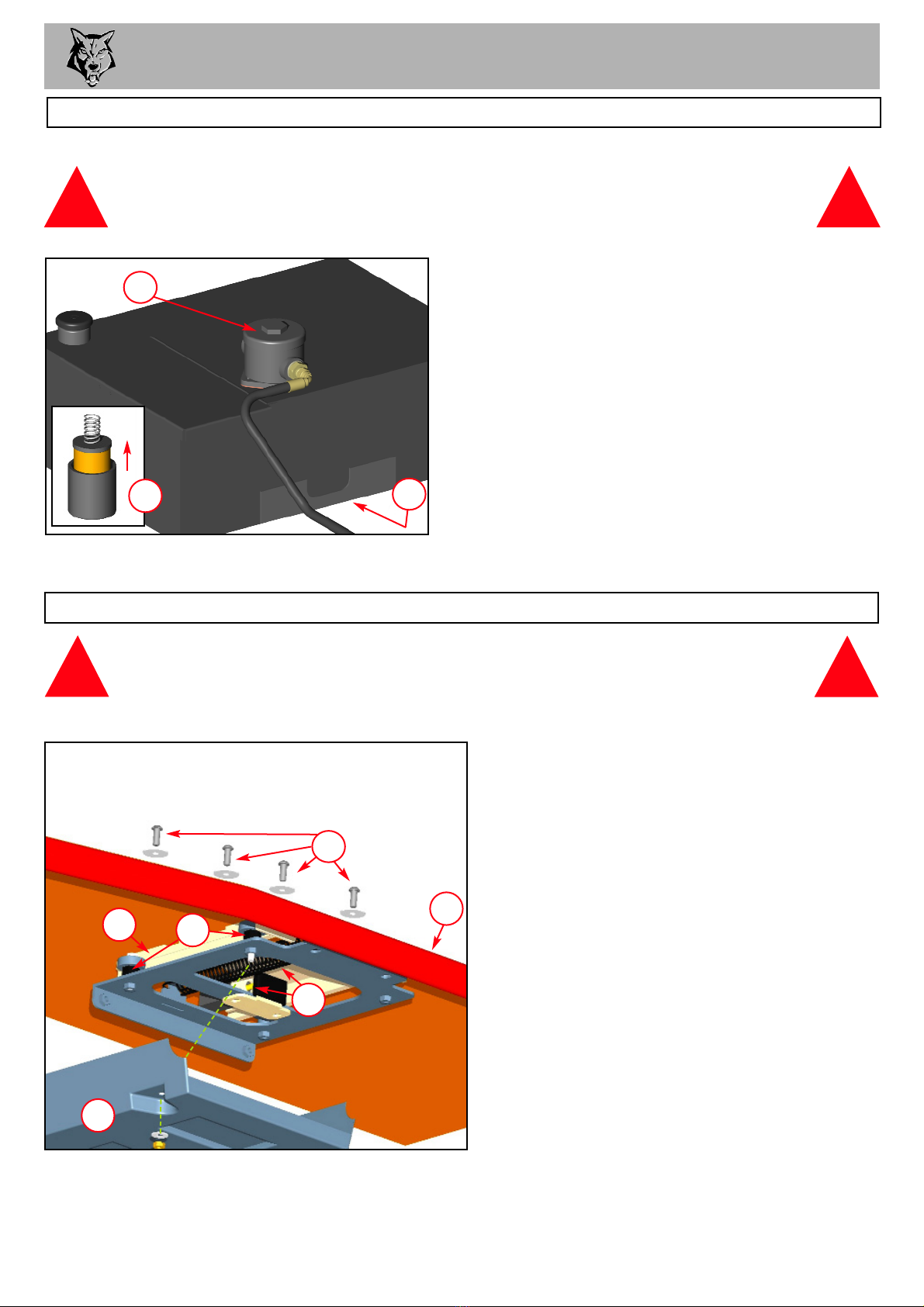
BATTERY REMOVAL AND MAINTENANCE
WARNING
Refer to the battery leaflet for safety and COSHH requirements. !
!
1. Remove the two M12 Nyloc nuts that retain the battery box top.
2. Remove the negative lead first and then the positive lead.
3. Clean, charge and/or top up the battery as required.
4. Refitting is the reverse of removal. Apply a smear of vaseline to the terminals to prevent
corrosion.

SERVICE INSTRUCTIONS 15
1. Turn the chipper off and remove the ignition keys.
2. Remove battery leads.
3. Remove bolt and washer retaining roller box
guard and lift guard.
4. Remove the two springs on the roller box slide.
5. NOTE: Rollerbox slide weighs in excess of 20kg.
Lift the roller box slide and wedge a suitably sized
piece of wood to hold in place.
6. Remove blade access cover.
7. Remove discharge tube. Turn the rotor by hand
by grasping fan section on rear of rotor disc until
blade is visible through aperture.
8. Use a small screwdriver to remove sap and debris
from Torx socket in screw - be particularly
careful to ensure every last piece has been
removed.
9. Undo blade screws using Torx socket drive
provided. Rotor will turn until Torx socket has
located on machine.
10. Before fitting replacement blades carefully
clean blade recess in rotor so that no debris
is trapped between blade and rotor.
11. When fitting blades replace any damaged
screws with new and coat each screw with
copperslip over the whole of the thread.
12. Retighten each screw to 60Nm (45lbs ft).
NOTE: This torque setting is vitally
important to ensure your bolts come out
at a later date and Entec recommend you
purchase a torque wrench for this and
other jobs on the chipper.
13. Grease all surfaces of the roller box sliding
mechanism (see fig.17, pg.18).
14. Replace blade access cover.
15. NOTE: Rollerbox slide weighs in excess of 20kg.
Remove wedge, lower roller box slide and
replace springs.
16. Close roller box guard and ensure bolt and
washer are tightened.
17. Refit battery leads.
WARNING
Wear riggers gloves for the blade changing operation.
CHANGE BLADES
fig 9. fig 10.
!
!
3
4
5
6
8
9
10
3
7
WARNING
Always sharpen blades on a regular basis. Failure to do so will
cause the machine to under perform and will overload engine and
bearings causing machine breakdown. Blades must not be
sharpened beyond the wear mark (see diagram). Failure to comply
with this could result in machine damage, injury or loss of life.
!
!
WEAR
MARK
fig 11.
SERVICE INSTRUCTIONS
TENSION HYDRAULIC PUMP BELT
1. Remove side panel.
2. Access the two nuts on the under side of the chassis beneath
pump bracket and slacken using a 19 mm socket spanner.
3. Adjust the M8 bolt on the outside plate until the desired tension is
achieved. Tension is correct when 4.5kg of force deflects one belt
6mm at the centre of its span. (Push the belt firmly with your index
finger, it should deflect to roughly the depth of your fingernail).
4. Ensure pulleys are aligned then retighten the two nuts to (80 Nm) 60 lbs/ft.
5. NOTE: Slack drive belts will cause poor performance and
belt/pulley wear.
The Timberwolf TW 35/150DH is subject to large vibrations during the normal course of operation.
Consequently there is always a possibility that nuts and bolts will work themselves loose. It is
important that periodic checks are made to ensure the security of all fasteners. Fasteners should be
tightened using a torque wrench to the required torque (see below).
Size Pitch Head Torque Nm Torque Ibft
General M8 Standard 13mm Hex 22 15
General M10 Standard 17mm Hex 45 32
General M12 Standard 19mm Hex 80 60
16
CHECK FITTINGS
TENSION DRIVE BELTS
CHECK HOSES
All the hydraulic hoses should be regularly inspected for chafing and leaks. The hydraulic system is
pressurized to over 130 Bar (1900 PSI) and thus the equipment containing it must be kept in good
condition.
Identify the hoses that run to the top motor. These have the highest chance of damage as they are
constantly moving. If any hydraulic components are changed new seals should be installed during
reassembly. Fittings should then be retightened.
2
fig 13.
3
1. Remove side panel.
2. Loosen bolt in centre of tensioner pulley with a 19mm spanner so
that pulley is able to slide with minimal wobble.
3. Turn nut in end of tensioner pulley slider until correct belt tension
is achieved and lock the tensioner pulley bolt back up again. Tension
is correct when 4.5kg of force deflects one belt 6mm at the centre of
its span. (Push the belt firmly with your index finger; it should
deflect to roughly the depth of your fingernail).
4. Run machine and test, recheck belt tension.
5. NOTE: Slack drive belts will cause poor performance and belt / pulley
wear.
2
3
fig 12.
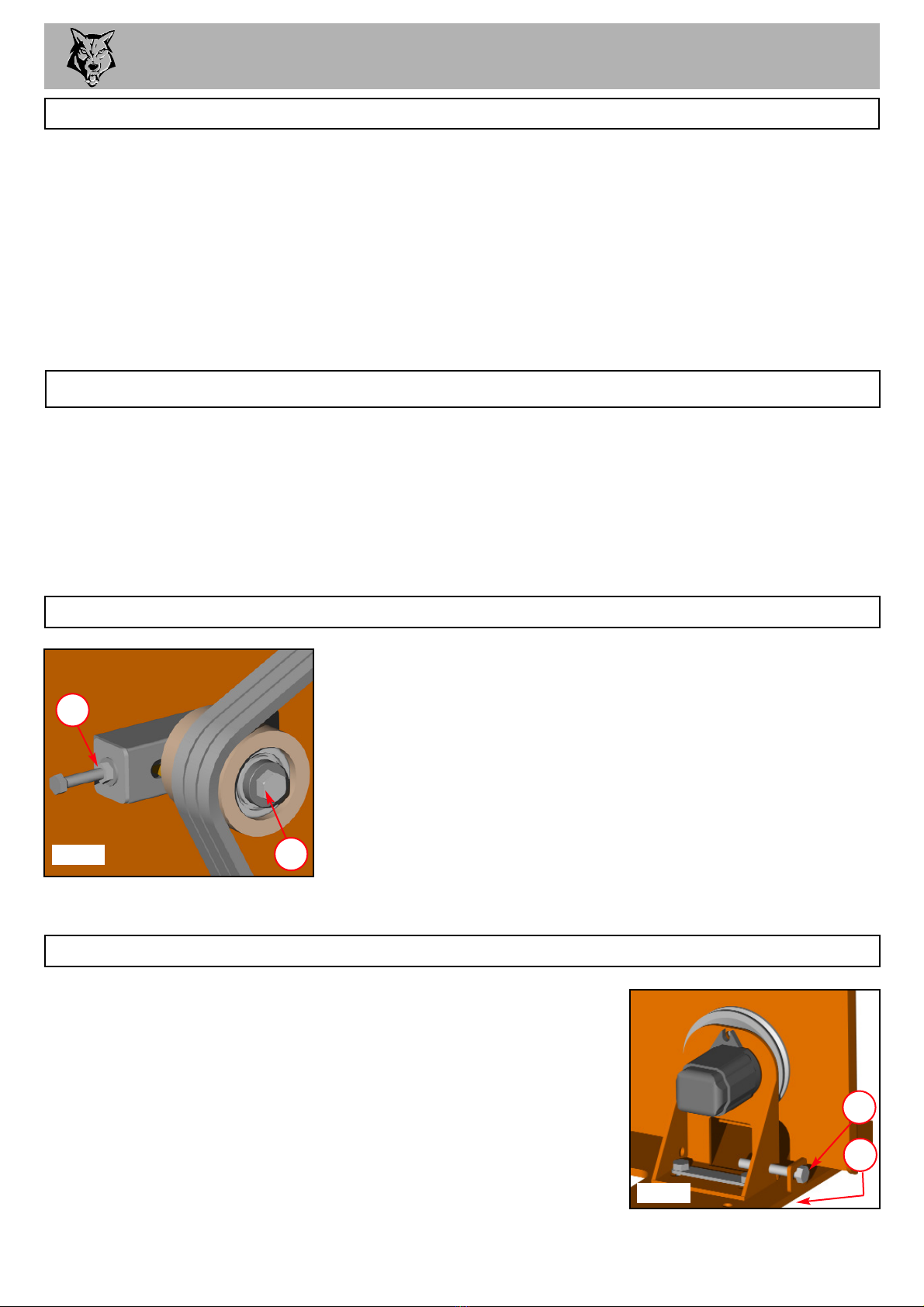
SERVICE INSTRUCTIONS 17
WARNING
To ensure that the safety bar is always available the following checks and
adjustments should be carried out monthly.
SERVICE TO THE SAFETY BAR (WHERE FITTED)
1. Remove the black plastic cover.
2. Use a bristle brush to remove any accumulated
debris or dirt.
3. Check that the switch is secure and the spring free
from debris.
4. Check all mounting bolts for security.
5. Hold the bar and check for side play. There should
not be any. If there is proceed as follows:
6. Locate the two hexagonal bearing pillars.
7. Slacken the screw on each pillar. The pillars are
eccentric. Turn the pillar slowly with a 19mm
spanner until the play just goes. Retighten the
pillar screws and check that the slide moves freely
without side play.
8. Apply fresh grease to each slide.
9. Refit the plastic cover.
!!
fig 15.
1
3
4
5
6
8
WARNING
Use plastic gloves to keep oil off skin and dispose of the used oil and filter in an
ecologically sound way. The oil and filter should be changed once a year
or at any time it becomes contaminated. Before starting check that
the chipper is standing level and brush away loose chips.
CHANGE HYDRAULIC OIL AND FILTER
1. Remove the black screw cap from the top of the filter
housing.
2. Partially remove filter element from inner cup. Leave
filter to drain for 15 minutes.
3. Remove filter element from cup when clear of hydraulic oil.
4. Remove drain plug and drain oil into a suitable container.
5. Replace drain plug.
6. Refill with VG 32 hydraulic oil until the level is half
way up the sight glass (about 15 litres).
7. Refit the filter cup, install a new filter element and refit the
black screw cap to the filter housing.
fig 14.
! !
2
1
4
NOTE: This is a non-adjustable air breather filter.

SERVICE INSTRUCTIONS 18
GREASE THE ROLLER DRIVE SPLINES
NOTE: This should be done four times a year or every 50 hours. If the grease in the splines is
allowed to dry out, rapid wear of the roller splines will occur resulting in a breakdown and the
need to fit replacement parts. This failure is not warranty.
1. Remove bolt and washer retaining roller box guard and lift guard (as
shown in fig 9).
2. Locate two grease nipples; one in the centre of each roller
shaft.
3. Use a pump action grease gun to apply a generous amount of
grease to each roller drive.
4. Close the roller box guard and refit the washer and bolt.
fig 16.
GREASE THE ROLLER BOX SLIDES
NOTE: This should be done regularly. In dirty or dusty conditions or during periods of hard
work it should be done weekly. If the slides become dry the top roller will tend to hang up and
the pulling-in power of the rollers will be much reduced. Excessive wear will ensue.
1. Turn the chipper off and remove the ignition keys.
2. Remove battery leads - ensure machine has come to a complete
stop.
3. Remove the bolt and washer retaining roller box guard and lift guard.
4. Remove the two springs on the roller box slide.
5. NOTE: Rollerbox slide weighs in excess of 20kg.
Lift the top roller and wedge a suitably sized piece of wood to hold
in place.
6. Apply thin grease with a brush to each slide on roller box and on
inner cheeks of slider.
7. NOTE: Rollerbox slide weighs in excess of 20kg.
Remove wedge, lower roller box slide and replace springs.
8. Close roller box guard and refit bolt and washer.
9. Refit battery leads.
fig 17.
ENGINE MANUFACTURER’S HANDBOOK
6
3
2
5
4
Refer to your Engine Manufacturer’s Handbook for detailed instructions on the following:
Changing the fuel filter.
Checking the engine oil.
Changing the engine oil.
Changing the engine oil filter.
GREASING ROTOR BEARINGS
Both front and rear bearings are sealed and do not need greasing.
This manual suits for next models
1
Table of contents
Other Entec Chipper manuals


